Herunterladen Inhalt Inhalt Diese Seite drucken
Grundfos RSL Montage- Und Betriebsanleitung

Grundfos RSL Montage- Und Betriebsanleitung

Rigid suction lances and foot valves
Inhaltsverzeichnis

Werbung

Verfügbare Sprachen
  • DE

Verfügbare Sprachen

  • DEUTSCH, seite 15
GRUNDFOS INSTRUCTIONS
Rigid suction lances, RSL
and foot valves, FV
Installation and operating instructions

Werbung

Inhaltsverzeichnis
loading

Inhaltszusammenfassung für Grundfos RSL

  • Seite 1 GRUNDFOS INSTRUCTIONS Rigid suction lances, RSL and foot valves, FV Installation and operating instructions...
  • Seite 3 Rigid suction lances, RSL and foot valves, FV English (GB) Installation and operating instructions ............4 Deutsch (DE) Montage- und Betriebsanleitung .
  • Seite 4: Inhaltsverzeichnis

    English (GB) Installation and operating instructions Original installation and operating instructions 1.4 Safety instructions for the operating company/operator CONTENTS The owner of the system is responsible for training of operating Page personnel. Safety instructions Warning 1.1 Symbols used in this document When working with chemicals, the accident 1.2 Qualification and training of personnel prevention regulations applicable at the installation...
  • Seite 5: Warranty

    Maintenance is carried out by authorised and qualified personnel. • Only original spare parts are used for repairs during maintenance. Grundfos cannot be held liable for any damage Note resulting from incorrect use. 2.5 Product description Fig. 1 From left to right: suction lance, foot valve with level indication, plastic and stainless-steel foot valve without level indication Pos.
  • Seite 6: Identification

    2.6 Identification 2.6.1 Type key of suction lances Code Example - 0500 - G5/8 / V,E / Rigid Suction Lance Maximum immersion depth 0400 up to 400 mm 0500 up to 500 mm 0570 up to 570 mm 0690 up to 690 mm 0820 up to 820 mm 0980...
  • Seite 7: Technical Data

    3. Technical data Foot valve and Foot valve and Foot valve Data suction lance suction lance (PE) (stainless steel) (PVDF) [l/h] Max. flow rate [gph] 15.85 [bar] Max. pressure [psi] Max. liquid temperature [°C] Mechanical data Min. liquid temperature [°C] Max.
  • Seite 8: Dimensions

    3.1 Dimensions Fig. 2 Left: rigid suction lance with / without level indication, right: foot valve with level indication Dimensions [mm] Code Suction lance Foot valve see type key 2.6.1 Type key of suction lances ≥ 114 ~ 103.5 ≥ 103 ~ 43.5 ~ 85 18.5...
  • Seite 9: Installation

    Avoid direct contact with chemicals. Wear protective clothing when handling chemicals. 4.1.1 Conditions for installation • Proper functioning can only be guaranteed when using Grundfos accessories. • For suction height and line diameter, please see the technical data of the pump. 4.1.2 Notes for installation •...
  • Seite 10: Electrical Connection Of Level Indication

    4.2 Electrical connection of level indication 4.2.3 Changing the contact type Suction lances and foot valves with two-step level indication have In order to monitor the filling level of the container, a two-step two signal outputs. Both are factory-set to NO contact type. level indication (low-level signal, tank-empty signal) can be The symbol is on the float switch top (see fig.
  • Seite 11: Container Connection

    4.3 Container connection 4. Fasten suction lance at hose connection. 4.3.1 Connecting to a Grundfos tank 1. Remove the screw cap from the tank. 2. Insert suction lance / foot valve into the threaded hole of the tank. Tighten the adapter screw manually.
  • Seite 12: Connecting To An Exchangeable Container

    4.3.2 Connecting to an exchangeable container 1. Select adapter type and immersion depth from the tables below. 2. Mount adapter on foot valve or suction lance. 3. Adapt immersion depth of foot valve or suction lance (see table). Immersion depth of suction lances Immersion Container type Volume [l]...
  • Seite 13: Maintenance And Service

    4. Cut a hole (∅60) into the container top surface and insert the suction lance. 5. Fix the suction lance with the counter nut. 6. Adapt the immersion depth of the suction lance (see section 4.3.1 Connecting to a Grundfos tank). Immersion depth of suction lances Immersion Container type...
  • Seite 14: Fault Finding

    Replace the foot valve or suction lance. 7. Disposal This product or parts of it must be disposed of in an environmentally sound way. Use appropriate waste collection services. If this is not possible, contact the nearest Grundfos company or service workshop. Subject to alterations.
  • Seite 15: Sicherheitshinweise

    Deutsch (DE) Montage- und Betriebsanleitung INHALTSVERZEICHNIS 1.4 Sicherheitshinweise für den Betreiber / Bediener Der Betreiber des Systems ist verantwortlich für die Schulung des Seite Bedienpersonals. Sicherheitshinweise 1.1 Verwendete Symbole Warnung 1.2 Qualifikation und Schulung des Personals Beim Arbeiten mit Chemikalien sind die am Aufstel- 1.3 Sicherer Betrieb lungsort gültigen Unfallverhütungsvorschriften zu 1.4 Sicherheitshinweise für den Betreiber / Bediener...
  • Seite 16: Gewährleistung

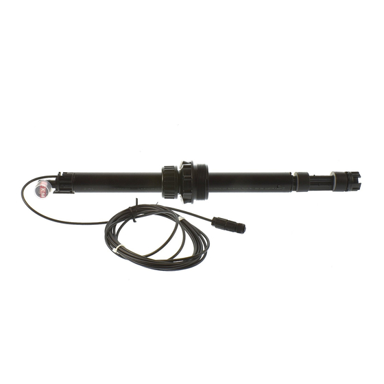
    Die Wartung wird nur von autorisiertem und qualifiziertem Per- sonal durchgeführt. • Bei der Wartung werden ausschließlich Original-Ersatzteile verwendet. Grundfos haftet nicht für Schäden, die durch fal- Hinweis schen Gebrauch entstehen. 2.5 Produktbeschreibung Abb. 1 Von links nach rechts: Starre Sauglanze, Fußventil mit Niveauüberwachung, Fußventil ohne Niveauüberwachung Kunststoff, - Edelstahl Pos.
  • Seite 17: Produktidentifikation

    2.6 Produktidentifikation 2.6.1 Typenschlüssel Sauglanzen Code Beispiel - 0500 - G5/8 / V,E / Sauglanze (Rigid Suction Lance) Maximale Eintauchtiefe 0400 bis 400 mm 0500 bis 500 mm 0570 bis 570 mm 0690 bis 690 mm 0820 bis 820 mm 0980 bis 980 mm 1100...
  • Seite 18: Technische Daten

    3. Technische Daten Fußventil und Fußventil und Fußventil Daten Sauglanze (PE) Sauglanze (PVDF) (Edelstahl) [l/h] Max. Durchfluss [gph] 15,85 [bar] Max. Druck [psi] Max. Medientemperatur [°C] Mechanische Daten Min. Medientemperatur [°C] Max. Umgebungstemperatur [°C] Min. Umgebungstemperatur [°C] Max. Lagertemperatur [°C] Min.
  • Seite 19: Abmessungen

    3.1 Abmessungen Abb. 2 Links: Starre Sauglanze mit / ohne Niveauüberwachung; rechts: Fußventil mit Niveauüberwachung Maß [mm] Bezeichnung Sauglanze Fußventil siehe Typenschlüssel 2.6.1 Typenschlüssel Sau- glanzen ≥ 114 ~ 103,5 ≥ 103 ~ 43,5 ~ 85 18,5 ~ 25 Abb. 3 Fußventil ohne Niveauüberwachung;...
  • Seite 20: Installation

    Tragen Sie Schutzkleidung beim Umgang mit Chemi- kalien. 4.1.1 Voraussetzungen für die Installation • Die einwandfreie Funktion kann nur bei Verwendung von Grundfos-Zubehör garantiert werden. • Angaben zu Saughöhe und Leitungsdurchmesser finden Sie in den technischen Daten der Pumpe. 4.1.2 Hinweise zur Installation •...
  • Seite 21: Elektrischer Anschluss Bei Niveauüberwachung

    4.2 Elektrischer Anschluss bei Niveauüberwachung 4.2.3 Kontaktart ändern Sauglanzen und Fußventile mit zweistufiger Niveauüberwachung Um den Füllstand im Behälter zu überwachen, kann eine zweistu- haben zwei Signalausgänge. Diese haben werkseitig die Kon- fige Niveauüberwachung (Vorleermeldung, Leermeldung) an die taktart Schließer (NO). Das Symbol befindet sich auf der Schwim- Pumpe oder andere nachfolgende Geräte angeschlossen wer- meroberseite (siehe Abb.
  • Seite 22: Behälter-Anschluss

    4.3 Behälter-Anschluss 4. Saugleitung am Schlauchanschluss befestigen. 4.3.1 Anschließen an einen Grundfos-Behälter 1. Schraubkappe vom Behälter entfernen. 2. Sauglanze / Fußventil in die Gewindeöffnung einsetzen, Schraubadapter von Hand anziehen. 3. Eintauchtiefe Sauglanze / Fußventil an die Behälterhöhe anpassen. Abb. 10 Saugleitung befestigen 5.
  • Seite 23: Anschließen An Ein Wechselgebinde

    4.3.2 Anschließen an ein Wechselgebinde 1. Adaptertyp und Eintauchtiefe aus den folgenden Tabellen auswählen. 2. Adapter auf Sauglanze / Fußventil montieren. 3. Eintauchtiefe Sauglanze / Fußventil anpassen (siehe Tabelle). Auswahl Eintauchtiefe Sauglanzen Eintauchtiefe Behälterart Volumen [l] [mm] L-Ring-Fass (blau) Stahlfass (Standard) 12, 33 Standard-Kanister nach 25, 30, 33...
  • Seite 24: Anschließen Einer Sauglanze An Ein Gebinde Ohne Dafür Vorgesehene Öffnung

    Grundfos-Behälter). Auswahl Eintauchtiefe Sauglanze Eintauchtiefe Behälterart Volumen [l] [mm] Zylindrische Grundfos Behäl- 1000 1200 Grundfos Behälter mit quad- ratischer Grundfläche Bei Verwendung in anderen Behältern muss die erforderliche Ein- tauchtiefe durch Messen ermittelt werden. Kontermutter Maße Material, Maßzeichnung Adaptertyp Produkt-Nr.
  • Seite 25: Störungsübersicht

    Defekter Reed-Schalter. Fußventil oder Sauglanze austauschen. 7. Entsorgung Dieses Produkt sowie Teile davon müssen umweltgerecht ent- sorgt werden. Nutzen Sie entsprechende Entsorgungsgesell- schaften. Ist das nicht möglich, wenden Sie sich bitte an die nächste Grundfos Gesellschaft oder Werkstatt. Technische Änderungen vorbehalten.
  • Seite 26: Sikkerhedsanvisninger

    Dansk (DK) Monterings- og driftsinstruktion Oversættelse af den originale engelske udgave 1.4 Sikkerhedsanvisninger for den driftsansvarlige virksomhed/brugeren INDHOLDSFORTEGNELSE Ejeren af anlægget er ansvarlig for oplæring af driftspersonalet. Side Advarsel Sikkerhedsanvisninger Ved arbejde med kemikalier skal ulykkesforebyg- 1.1 Symboler brugt i dette dokument gende foranstaltninger overholdes på...
  • Seite 27: Garanti

    Vedligeholdelse udføres af autoriseret og kvalificeret perso- nale. • Der bruges kun originale reservedele i forbindelse med repa- ration under vedligeholdelse. Grundfos er ikke ansvarlig for skader der opstår som Bemærk følge af forkert brug. 2.5 Produktbeskrivelse Fig. 1 Fra venstre mod højre: sugelanse, bundventil med niveauvisning, bundventil i plastic og rustfrit stål uden niveauvisning Pos.
  • Seite 28: Identifikation

    2.6 Identifikation 2.6.1 Typenøgle for sugelanser Kode Eksempel - 0500 - G5/8 / V,E / Stiv sugelanse Maks. nedsænkningsdybde 0400 op til 400 mm 0500 op til 500 mm 0570 op til 570 mm 0690 op til 690 mm 0820 op til 820 mm 0980 op til 980 mm...
  • Seite 29: Tekniske Data

    3. Tekniske data Bundventil og Bundventil og Bundventil Data sugelanse (PE) sugelanse (PVDF) (rustfrit stål) [l/t] Maks. flow [gph] 15,85 [bar] Maks. tryk [psi] Maks. medietemperatur [°C] Mekaniske data Min. medietemperatur [°C] Maks. omgivelsestemperatur [°C] Min. omgivelsestemperatur [°C] Maks. lagertemperatur [°C] Min.
  • Seite 30: Mål

    3.1 Mål Fig. 2 Venstre: stiv sugelanse med/uden niveauvisning. Højre: bundventil med niveauvisning Mål [mm] Kode Sugelanse Bundventil se typenøgle 2.6.1 Typenøgle for sugelanser ≥ 114 ~ 103,5 ≥ 103 ~ 43,5 ~ 85 18,5 ~ 25 68,5 Fig. 3 Bundventil uden niveauvisning.
  • Seite 31: Installation

    Undgå direkte kontakt med kemikalier. Brug beskyt- telsesdragt ved håndtering af kemikalier. 4.1.1 Installationsbetingelser • Vi kan kun garantere korrekt funktion ved anvendelse af udstyr og dele fra Grundfos. • Sugehøjde og ledningsdiameter fremgår af pumpens tekniske data. 4.1.2 Installationsbemærkninger •...
  • Seite 32: Eltilslutning For Niveauvisning

    4.2 Eltilslutning for niveauvisning 4.2.3 Ændring af kontakttype Sugelanser og bundventiler med totrins niveauvisning har to sig- For at overvåge beholderens væskestand kan der sluttes en naludgange. Begge er fabriksindstillet som sluttekontakt (NO). totrins niveauvisning (signal for lavt niveau, signal for tom behol- Symbolet findes på...
  • Seite 33: Beholdertilslutning

    4.3 Beholdertilslutning 4. Fastgør sugelansen til slangetilslutningen. 4.3.1 Tilslutning til en Grundfos-beholder 1. Fjern skruelåget fra beholderen. 2. Indfør sugelansen/bundventilen i beholderens gevindhul. Til- spænd adapterskruen med fingrene. 3. Tilpas sugelansens/bundventilens neddypningsdybde til beholderens højde. Fig. 10 Fastgørelse af sugelansen 5.
  • Seite 34 4.3.2 Tilslutning til en udskiftelig beholder 1. Vælg adaptertype og neddypningsdybde i tabellen nedenfor. 2. Montér adapteren på bundventilen eller sugelansen. 3. Tilpas bundventilens eller sugelansens neddypningsdybde (se tabel). Neddypningsdybde for sugelanser Neddypnings- Beholdertype Volumen [l] dybde [mm] L-rings-tønde (blå) Ståltønde (standard) 12, 33 (stor Flad standardbenzindunk...
  • Seite 35: Vedligeholdelse Og Service

    3. Tilpas sugelansens neddypningsdybde (se afsnit 4.3.1 Tilslutning til en Grundfos-beholder). Neddypningsdybde for sugelanser Neddypnings- Beholdertype Volumen [l] dybde [mm] Cylindrisk Grundfos-beholder 1000 1200 Firkantet Grundfos-beholder Ved brug af andre beholdere skal den krævede neddypnings- dybde bestemmes ved måling. Kontramøtrik Mål Materiale, Måltegning...
  • Seite 36: Fejlfinding

    Udskift bundventilen eller sugelansen. 7. Bortskaffelse Dette produkt eller dele heraf skal bortskaffes på en miljørigtig måde. Brug de offentlige eller godkendte, private renovationsord- ninger. Hvis det ikke er muligt, kontakt nærmeste Grundfos-sel- skab eller -serviceværksted. Ret til ændringer forbeholdes.
  • Seite 37: Instrucciones De Seguridad

    Español (ES) Instrucciones de instalación y funcionamiento Traducción de la versión original en inglés 1.4 Instrucciones de seguridad para la empresa operadora/operario CONTENIDO El propietario del sistema es responsable de la formación del per- Página sonal operativo. Instrucciones de seguridad Aviso 1.1 Símbolos utilizados en este documento Cuando se trabaja con productos químicos, debe...
  • Seite 38: Garantía

    Los trabajos de mantenimiento los ha realizado personal auto- rizado y cualificado. • Únicamente se han utilizado recambios originales en las repa- raciones realizadas durante el mantenimiento. Grundfos no se hace responsable de los daños cau- Nota sados por el uso incorrecto. 2.5 Descripción del producto Fig. 1 De izquierda a derecha: lanza de aspiración, válvula de pie con indicación de nivel, válvula de pie de plástico y acero...
  • Seite 39: Identificación

    2.6 Identificación 2.6.1 Nomenclatura de las lanzas de aspiración Código Ejemplo - 0500 - G5/8 / V,E / Lanza rígida de aspiración Profundidad máxima de inmersión 0400 Hasta 400 mm 0500 Hasta 500 mm 0570 Hasta 570 mm 0690 Hasta 690 mm 0820 Hasta 820 mm 0980...
  • Seite 40: Datos Técnicos

    3. Datos técnicos Válvula de pie y Válvula de pie y Válvula de pie Datos lanza de aspiración lanza de aspiración (acero inoxidable) (PE) (PVDF) [l/h] Caudal máximo [gal/hora] 15,85 [bar] Presión máxima [psi] Temperatura máx. del líquido [°C] Temperatura mínima del líquido [°C] Datos mecánicos Temperatura ambiente máxima...
  • Seite 41: Dimensiones

    3.1 Dimensiones Fig. 2 Izquierda: lanza rígida de succión con / sin indicación de nivel, derecha: válvula de pie con indicación de nivel Dimensiones [mm] Código Lanza de aspiración Válvula de pie Véase la nomenclatura 2.6.1 Nomenclatura de las lanzas de aspiración ≥...
  • Seite 42: Instalación

    4.1.1 Condiciones para la instalación • Solo se puede garantizar el funcionamiento adecuado cuando se utilicen accesorios de Grundfos. • Para la altura de aspiración y el diámetro de la tubería, véanse los datos técnicos de la bomba.
  • Seite 43: Conexión Eléctrica Para La Indicación De Nivel

    4.2 Conexión eléctrica para la indicación de nivel 4.2.3 Cambio del tipo de contacto Las lanzas de aspiración y las válvulas de pie con indicación de Para controlar el nivel de llenado del recipiente, se puede conec- nivel de dos etapas tienen dos salidas de señal. Ambas están tar una indicación de nivel de dos etapas (señal de nivel bajo, configuradas de fábrica con el tipo de contacto NO.
  • Seite 44: Conexión Del Recipiente

    4.3 Conexión del recipiente 4. Enganche la lanza de aspiración a la conexión del tubo flexi- ble. 4.3.1 Conexión a un tanque Grundfos 1. Retire el tapón roscado del tanque. 2. Introduzca la lanza de aspiración / válvula de pie en el orificio roscado del tanque.
  • Seite 45 4.3.2 Conexión a un recipiente intercambiable 1. Seleccione el tipo de adaptador y la profundidad de inmersión de las siguientes tablas. 2. Monte el adaptador en la válvula de pie o en la lanza de aspi- ración. 3. Adapte la profundidad de inmersión de la válvula de pie o de la lanza de aspiración (véase la tabla).
  • Seite 46: Mantenimiento Y Reparación

    Profundidad de inmersión de las lanzas de aspiración Profundidad Tipo de recipiente Volumen [l] de inmersión [mm] Tanque cilíndrico de Grundfos 1000 1200 Tanque cuadrado de Grundfos Si se utilizan otros recipientes, la profundidad de inmersión nece- saria se debe determinar midiendo.
  • Seite 47: Localización De Averías

    Este producto o sus piezas deben eliminarse de forma ecológica- mente responsable. Utilice los servicios adecuados de recogida de residuos. Si esto no es posible, póngase en contacto con el distribuidor o servicio técnico Grundfos más cercano. Nos reservamos el derecho a modificaciones.
  • Seite 48: Consignes De Securite

    Français (FR) Notice d'installation et de fonctionnement Traduction de la version anglaise originale 1.3 Fonctionnement sécurisé Si le fonctionnement sécurisé ne peut plus être assuré, le produit SOMMAIRE doit être mis hors service. Page Cela est applicable dans les cas suivants : •...
  • Seite 49: Fonction

    • Seules des pièces détachées d'origine doivent être utilisées • Connexion d'un conteneur échangeable. pour les réparations. Grundfos décline toute responsabilité pour tout dom- Nota mage résultant d'une utilisation non conforme. 2.5 Description du produit Fig. 1 De gauche à droite : crépine d'aspiration, clapet de pied avec indication du niveau, clapet de pied en plastique et en acier inoxydable sans indication du niveau Pos.
  • Seite 50: Identification

    2.6 Identification 2.6.1 Désignation des crépines d'aspiration Code Exemple - 0500 - G5/8 / V,E / Crépine d'aspiration rigide Profondeur d'immersion maxi 0400 Jusqu'à 400 mm 0500 Jusqu'à 500 mm 0570 Jusqu'à 570 mm 0690 Jusqu'à 690 mm 0820 Jusqu'à 820 mm 0980 Jusqu'à...
  • Seite 51: Caractéristiques Techniques

    3. Caractéristiques techniques Clapet de pied et Clapet de pied et Clapet de pied Données crépine d'aspiration crépine d'aspiration (acier inoxydable) (PE) (PVDF) [l/h] Débit maxi [gph] 15,85 [bar] Pression maxi [psi] Température maxi du liquide [°C] Caractéristiques mécaniques Température mini du liquide [°C] Température ambiante maxi [°C]...
  • Seite 52: Dimensions

    3.1 Dimensions Fig. 2 Gauche : crépine d'aspiration rigide avec/sans indication du niveau, droite : clapet de pied avec indication du niveau Dimensions [mm] Code Crépine d'aspiration Clapet de pied voir désignation 2.6.1 Désignation des crépines d'aspiration ≥ 114 ~ 103,5 ≥...
  • Seite 53: Installation

    4.1.1 Conditions d'installation • Un bon fonctionnement peut uniquement être garanti en cas d'utilisation des accessoires Grundfos. • Pour la hauteur d'aspiration et le diamètre de la tuyauterie, consulter les caractéristiques techniques de la pompe. 4.1.2 Notes pour l'installation •...
  • Seite 54: Connexion Électrique De L'indication Du Niveau

    4.2 Connexion électrique de l'indication du niveau 4.2.3 Changement du type de contact Les crépines d'aspiration et les clapets de pied avec indication du Afin de surveiller le niveau de remplissage du conteneur, une niveau à deux étapes sont équipés de deux sorties. indication du niveau à...
  • Seite 55: Raccordement Du Conteneur

    4.3 Raccordement du conteneur 4. Fixer la crépine d'aspiration sur le raccord tuyauterie. 4.3.1 Raccordement à un réservoir Grundfos 1. Retirer le bouchon vissé du réservoir. 2. Insérer la crépine d'aspiration/le clapet de pied dans l'orifice fileté du réservoir. Serrer l'adaptateur manuellement.
  • Seite 56 4.3.2 Raccordement à un conteneur échangeable 1. Sélectionner le type d'adaptateur et la profondeur d'immersion en se basant sur les tableaux ci-dessous. 2. Monter l'adaptateur sur le clapet de pied ou la crépine d'aspi- ration. 3. Régler la profondeur d'immersion du clapet de pied ou de la crépine d'aspiration (voir tableau).
  • Seite 57: Maintenance Et Entretien

    Grundfos). Profondeur d'immersion des crépines d'aspiration Profondeur Type de conteneur Volume [l] d'immersion [mm] Bac cylindrique Grundfos 1000 1200 Bac carré Grundfos Lorsque vous utilisez d'autres conteneurs, la profondeur d'immer- sion nécessaire doit être déterminée par plusieurs mesures. Contre-écrou Dimensions Matériau,...
  • Seite 58: Grille De Dépannage

    Ce produit ou les pièces de celui-ci doivent être mis au rebut dans le respect de l'environnement. Utiliser votre service local de collecte des déchets. Si ce n'est pas possible, envoyer ce produit à Grundfos ou au réparateur agreé Grundfos le plus proche. Nous nous réservons tout droit de modifications.
  • Seite 59: Veiligheidsinstructies

    Nederlands (NL) Installatie- en bedieningsinstructies Vertaling van de oorspronkelijke Engelse versie 1.4 Veiligheidsinstructies voor het bedrijf / de operator De eigenaar van het systeem is verantwoordelijk voor de oplei- INHOUD ding van het bedienend personeel. Pagina Waarschuwing Veiligheidsinstructies Bij werkzaamheden met chemicaliën moet de regel- 1.1 Symbolen die in dit document gebruikt worden geving ter voorkoming van ongelukken die van toe- 1.2 Kwalificatie en training van het personeel...
  • Seite 60: Garantie

    • Tijdens het onderhoud worden reparaties alleen met originele onderdelen uitgevoerd. Grundfos kan niet aansprakelijkheid gesteld worden N.B. voor schade die voortvloeit uit onjuist gebruik. 2.5 Productomschrijving Afb. 1 Van links naar rechts: zuiglans, voetklep met niveauweergave, kunststof en roestvrijstalen voetklep zonder niveauweergave Pos.
  • Seite 61: Identificatie

    2.6 Identificatie 2.6.1 Typecodering voor zuiglansen Code Voorbeeld - 0500 - G5/8 / V,E / Onbuigzame zuiglans Maximale dompeldiepte 0400 tot 400 mm 0500 tot 500 mm 0570 tot 570 mm 0690 tot 690 mm 0820 tot 820 mm 0980 tot 980 mm 1100 tot 1100 mm...
  • Seite 62: Technische Specificaties

    3. Technische specificaties Voetklep en Voetklep en Data Voetklep (RVS) zuiglans (PE) zuiglans (PVDF) [l/uur] Max. debiet [gph] 15,85 [bar] Max. druk [psi] Max. vloeistoftemperatuur [°C] Mechanische spe- cificaties Min. vloeistoftemperatuur [°C] Max. omgevingstemperatuur [°C] Min. omgevingstemperatuur [°C] Max. opslagtemperatuur [°C] Min.
  • Seite 63: Afmetingen

    3.1 Afmetingen Afb. 2 Links: starre zuiglans met / zonder niveauweergave, rechts: voetklep met niveauweergave Afmetingen [mm] Code Zuiglans Voetklep zie typecodering 2.6.1 Typecodering voor zuiglansen ≥ 114 ~ 103,5 ≥ 103 ~ 43,5 ~ 85 18,5 ~ 25 68,5 Afb.
  • Seite 64: Installatie

    Draag beschermende kleding wanneer u omgaat met chemicaliën. 4.1.1 Installatievoorwaarden • De goede werking kan alleen worden gegarandeerd wanneer u gebruikmaakt van Grundfos-toebehoren. • Voor de zuighoogte en leidingdiameter raadpleegt u de techni- sche gegevens van de pomp. 4.1.2 Opmerkingen voor de installatie •...
  • Seite 65: Elektrische Aansluiting Van Niveauweergave

    4.2 Elektrische aansluiting van niveauweergave 4.2.3 Het contacttype wijzigen Zuiglansen en voetkleppen met een niveauweergave in twee Om het vulniveau van de recipiënt te volgen, kan een niveau- stappen hebben twee signaaluitgangen. Beide zijn in de fabriek weergave in twee stappen (laag niveau, tank leeg) worden aan- ingesteld op het NO-contacttype.
  • Seite 66: Aansluiting Op Recipiënt

    4.3 Aansluiting op recipiënt 4. Maak de zuiglans vast aan de slangaansluiting. 4.3.1 Aansluiten op een Grundfos-tank 1. Verwijder de schroefdop van de tank. 2. Plaats zuiglans / voetklep in de opening met schroefdraad van de tank. Draai de adapterschroef met de hand vast.
  • Seite 67 4.3.2 Een verwisselbare recipiënt aansluiten 1. Selecteer adaptertype en dompeldiepte uit de onderstaande tabellen. 2. Monteer de adapter op de voetklep of zuiglans. 3. Pas de dompeldiepte van de voetklep of zuiglans aan (zie tabel). Dompeldiepte van zuiglansen Dompel- Type recipiënt Inhoud [l] diepte [mm] L-ring vat (blauw)
  • Seite 68: Een Zuiglans Aansluiten Op Een Recipiënt Zonder Opening

    (zie hoofdstuk 4.3.1 Aansluiten op een Grundfos-tank). Dompeldiepte van zuiglansen Dompel- Type recipiënt Inhoud [l] diepte [mm] Grundfos cilindrische tank 1000 1200 Grundfos vierkante tank Wanneer andere recipiënten worden gebruikt, moet de dompel- diepte worden bepaald door meting. Contramoer Afmetingen...
  • Seite 69: Opsporen Van Storingen

    Dit product of delen ervan dienen te worden afgevoerd op een milieuverantwoorde wijze. Maak gebruik van de juiste afvalver- werkingsdiensten. Als dat niet mogelijk is, neem dan contact op met een filiaal of servicedienst van Grundfos het dichtst bij u in de buurt. Wijzigingen voorbehouden.
  • Seite 70: Указания По Технике Безопасности

    Русский (RU) Паспорт, Руководство по монтажу и эксплуатации Перевод оригинального документа на английском языке 1.3 Безопасная эксплуатация Если безопасная эксплуатация больше невозможна, СОДЕРЖАНИЕ необходимо вывести оборудование из эксплуатации и принять меры по недопущению его случайного Стр. использования. Указания по технике безопасности Такая...
  • Seite 71: Назначение

    резервуара с применением двух герконовых реле и • для ремонта использовались только оригинальные поплавковых уровнемеров. запасные части. • Подсоединение сменного контейнера. Компания Grundfos не несёт ответственности за какие-либо повреждения, возникшие в результате Указание ненадлежащего использования. 2.5 Общие сведения об изделии • Рис. 1 Слева...
  • Seite 72: Маркировка

    2.6 Маркировка 2.6.1 Типовое обозначение всасывающих линий Код Пример - 0500 - G5/8 / V,E / Жёсткая всасывающая линия Максимальная глубина погружения 0400 до 400 мм 0500 до 500 мм 0570 до 570 мм 0690 до 690 мм 0820 до 820 мм 0980 до...
  • Seite 73: Технические Данные

    3. Технические данные Приёмный клапан Приёмный клапан Приёмный клапан Данные и всасывающая и всасывающая (нержавеющая линия (ПЭ) линия (ПВДФ) сталь) [л/ч] Макс. расход [гал/ч] 15,85 [бар] Макс. давление [фунт/кв. дюйм] Макс. температура жидкости [°C] Механические Мин. температура жидкости [°C] характеристики Макс.
  • Seite 74: Размеры

    3.1 Размеры Рис. 2 Слева: жёсткая всасывающая линия с индикацией уровня или без таковой, справа: приёмный клапан с индикацией уровня Размеры, мм Код Всасывающая Приёмный клапан линия см. типовое обозначение 2.6.1 Типовое обозначение всасывающих линий ≥ 114 ~ 103,5 ≥ 103 ~ 43,5 ~ 85 18,5...
  • Seite 75: Монтаж

    реагентами. Для работы с реагентами необходимо надеть защитную одежду. 4.1.1 Условия монтажа • Надлежащее функционирование может гарантироваться только при использовании принадлежностей производства компании Grundfos. • Высота всасывания и диаметр линии указаны в технических характеристиках насоса. 4.1.2 Замечания по монтажу •...
  • Seite 76: Электрическое Соединение Индикации Уровня

    4.2 Электрическое соединение индикации уровня 4.2.3 Изменение типа контакта Всасывающие линии и приёмные клапаны с двухпозиционной Для контроля уровня заполнения резервуара к насосу или индикацией уровня имеют два сигнальных выхода. Заводская иным устройствам со стороны выхода может быть настройка типа контакта обоих выходов - НР (нормально подключена...
  • Seite 77: Подсоединение К Резервуару

    4.3 Подсоединение к резервуару 4. Закрепите всасывающую линию на соединении шланга. 4.3.1 Подсоединение к резервуару Grundfos 1. Снимите резьбовую крышку с резервуара. 2. Вставьте всасывающую линию/приёмный клапан в резьбовое отверстие резервуара. Вручную затяните переходный винт. 3. Отрегулируйте глубину погружения всасывающей...
  • Seite 78 4.3.2 Подключение к сменному контейнеру 1. Выберите тип переходника и глубину погружения в таблице, представленной ниже. 2. Установите переходник на приёмный клапан или всасывающую линию. 3. Отрегулируйте глубину погружения приёмного клапана или всасывающей линии (см. таблицу). Глубина погружения всасывающих линии Глубина...
  • Seite 79: Сервис И Техническое Обслуживание

    1. Вырежьте отверстие (∅60) в верхней поверхности контейнера и вставьте всасывающую линию. 2. Закрепите всасывающую линию при помощи контргайки. 3. Отрегулируйте глубину погружения всасывающей линии (см. раздел 4.3.1 Подсоединение к резервуару Grundfos). Глубина погружения всасывающих линий Глубина Тип контейнера Объём, л погружения, мм...
  • Seite 80: Обнаружение И Устранение Неисправностей

    7. Утилизация отходов Данное изделие, а также его части должны утилизироваться в соответствии с экологическими нормами и правилами. Используйте услуги организаций по сбору и переработке отходов. Если это невозможно, обратитесь в ближайшее представительство или сервисный центр компании Grundfos. Возможны технические изменения.
  • Seite 83 Phone: +852-27861706 / 27861741 Telefax: +47-22 32 21 50 Canada Telefax: +852-27858664 Turkey Poland GRUNDFOS Canada Inc. GRUNDFOS POMPA San. ve Tic. Ltd. Sti. Hungary 2941 Brighton Road GRUNDFOS Pompy Sp. z o.o. Gebze Organize Sanayi Bölgesi Oakville, Ontario GRUNDFOS Hungária Kft.
  • Seite 84 98131771 0316 ECM: 1180910 www.grundfos.com...

Diese Anleitung auch für:

Fv

Inhaltsverzeichnis