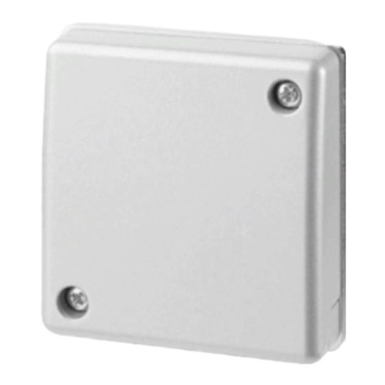
Inhaltszusammenfassung für Vanderbilt GM775LSNi
- Seite 1 GM775LSNi (en) Seismic detector (de) Körperschallmelder Installation manual: A6V10276498_b Edition: 01.10.2015 A5Q00038199 A6V10276498_b...
- Seite 2 A6V10276498_b...
- Seite 3 The anti-tamper system for the similar materials will impede the acoustics. Remove cover (Fig. 1, item A) and on the back of the GM775LSNi will these materials from the mounting location before detect the opening or the forcible removal of the detector.
- Seite 4 GMXP0 displays a detector symbol to indicate the Fig. 1, item J in ON position direction of the cable access to the detector. (default setting) Take note of the orientation of the GM775LSNi seismic detector and the required orientation of the GMXP0 mounting plate. GMXP0 drill symbol...
-
Seite 5: Function Test
*Modes not available in GM570LSN compatibility mode *Availability of these options depends on the ability of the control panel to identify the detector as a GM775LSNi. Some control panels may identify the GM775LSNi as a GM570LSN. 11.1. Function test The LSNi/LSN control panel can trigger a function test in conjunction with an installed GMXS1 internal test transmitter. - Seite 6 Sicherheit gegen Falschalarm. Der removal Sabotageschutz in der Melderabdeckung (Abb. 1, Element A) und External tamper contact auf der Rückseite des GM775LSNi erkennt ein Öffnen und ein (Fig.6, terminal 11) gewaltsames Entfernen des Melders. < 20 kΩ Die Montage, Programmierung und Inbetriebnahme Closed resistor müssen durch Fachpersonen erfolgen.
-
Seite 7: Direkte Montage Auf Stahl
5.3. Montage auf Beton mithilfe der Montageplatte GMXP0 8. Konfiguration (LSNi/LSN-Adressierung) Verwenden Sie die Seite der Montageplatte GMXP0 mit dem Der GM775LSNi unterstützt LSNi (LSN improved) und LSN (LSN Bohrsymbol (Abb. 4), um den Melder auf Betonflächen zu classic). Der Melder muss mithilfe der zwei DIP-Schalter montieren. -
Seite 8: Automatischer Selbsttest
Sabo und Klemme 8 GND (Abb. 6) an. *Ob diese Optionen verfügbar sind, hängt davon ab, inwiefern die Zentrale den Melder als einen GM775LSNi erkennt. Einige Der externe Sabotagekontakt wird über den DIP-Schalter (Abb. 1, Zentralen könnten den GM775LSNi als ein GM570LSN Element J) mit Schalter 2 in der EIN-Position wie folgt aktiviert: identifizieren. - Seite 9 Luftfeuchtigkeit (EN 60721), nicht < 95 % durchgehend verschweißt kondensierend Zulassungen Siehe Typenschild auf Innenseite der Abdeckung (Abb. 5) 16. Bestellangaben GM775LSNi V54534-F114-A100 Körperschallmelder GMXP0 VBPZ:2772730001 Montageplatte – GM7xx GMXS1 VBPZ:4202370001 Ein Melder für jeweils maximal 5 Wandelemente. Der Melder Interner Prüfsender –...
- Seite 10 GMXP3 VBPZ:3470190001 Schlossschutz – GM7xx GMXP3Z VBPZ:5712410001 Schlossschutz – GM7xx GMAS6 VBPZ:4886060001 Bewegliches Montagekit – GM7xx GMXD7 VA5Q00006245 Bohrschutzfolie (10×) – GM730/760/775 GMXC2 V54534-F101-A100 Anschlussmuffe (16 mm) – GM7xx A6V10276498_b...
-
Seite 11: Anhang
Appendix Anhang Settings for the LSNi operating mode with manual addressing Einstellungen für die Betriebsart LSNi mit manueller Adressierung Switch setting Fig. 1, item G Schalterstellung Fig. 1, item G O = OFF 1 = ON O = OFF 1 = ON Adresse LSNi auto LSN classic...


