Werbung
Quicklinks
BETRIEBSANLEITUNG
OPERATING INSTRUCTIONS
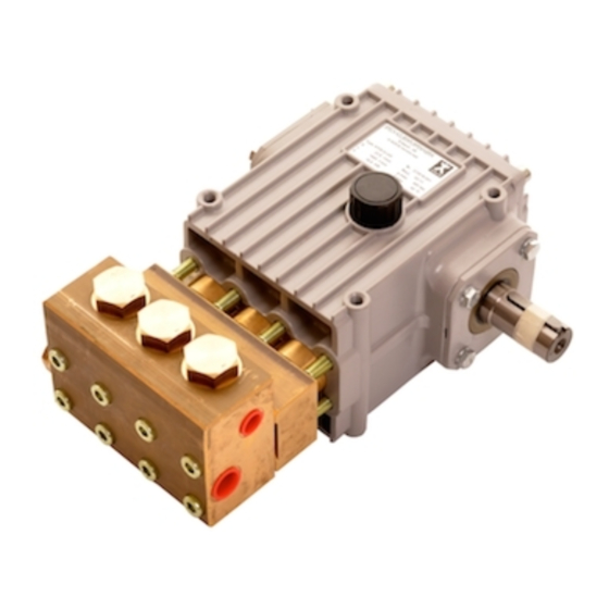
SPECK-TRIPLEX-PLUNGERPUMPE
SPECK TRIPLEX PLUNGER PUMP
Leistungsbereich - Performance
Type
Best.-Nr. Leistungs-
Code
No.
NP25/11-500RKT 00.6703
NP25/12-500RKT 00.6876
NPSH erf. ist gültig für Wasser (spez. Gewicht 1kg/dm
zulässiger Pumpendrehzahl.
Inbetriebnahme und Wartung
Vor
Inbetriebnahme
Ölstand
Wasserzulauf sorgen.
Bei Frostgefahr muss das Wasser aus der Pumpe und den
angrenzenden Anlagenteilen (insbesondere auch das UL-Ventil) entleert
werden. Zum Entleeren kann der zweite, unbenutzte Druckanschluß ver-
wendet werden. Hierzu kann die Pumpe ca. 1-2 Minuten „trocken" laufen.
Ölfüllmenge 0,8 l. Nur Getriebeöl ISO VG 220 GL4 (z.B. Aral Degol
BG220) oder KFZ- Getriebeöl SAE 90 GL4 verwenden.
Erster Ölwechsel nach 50 Betriebsstunden, danach alle 500
Betriebsstunden, spätestens jedoch nach 1 Jahr. Achtung bei Betrieb in
feuchten Räumen bzw. bei hohen Temperaturschwankungen. Bei
Kondenswasserbildung im Getrieberaum (Aufschäumen des Öles)
sofort Ölwechsel durchführen.
NPSH-Wert beachten!
Max. Zulaufdruck 10 bar, max. Saughöhe -0.3 bar. Darauf achten, dass
die Saugpulsation ausreichend gedämpft wird – Resonanz der starren
Wassersäule muss unbedingt vermieden werden.
Bei Nichtgebrauch der Pumpe können die Dichtungen
(18/23) verspröden oder aushärten, so dass es bei Inbetriebnahme zu
Wasserleckage kommt.
In diesem Fall sollten die Dichtungen vorsichtshalber alle 4 Jahre
erneuert werden.
Sicherheitsvorschriften
Es
ist
ein
Sicherheitsventil
Flüssigkeitsstrahler vorzusehen, das so eingestellt ist, dass der
Betriebsdruck um nicht mehr als 10 % überschritten werden kann. Bei
Nichteinhaltung dieser Vorschrift sowie bei Überschreiten der
Temperatur- und Drehzahlgrenze erlischt jegliche Gewährleistung.
Beim Betrieb der Pumpe muss die angetriebene Wellenseite und
Kupplung durch einen bauseitigen Berührungsschutz abgedeckt sein.
Vor Wartungsarbeiten an Pumpe und Anlage muss sichergestellt
werden, dass Druckleitung und Pumpe drucklos sind! Saugleitung
verschließen.
Versehentliches
Starten
des
Maßnahmen vermeiden (Sicherungen herausschrauben).
Vor Inbetriebnahme Pumpe und druckseitige Anlagenteile drucklos
entlüften. Ansaugen und Fördern von Luft oder Luft-Wassergemisch
sowie Kavitation unbedingt vermeiden.
Kavitation
bzw.
Kompression
unkontrollierbaren
Druckstößen
Anlagenteile zerstören sowie Bedienungspersonal gefährden!
SPECK-TRIPLEX-Pumpen sind geeignet zur Förderung von sauberem
Wasser oder anderen nicht aggressiven oder abrassiven Medien mit
ähnlichem spezifischen Gewicht wie Wasser.
Werden andere Flüssigkeiten, insbesondere brennbare, explosive
und toxische Medien gefördert, so ist eine Rücksprache mit dem
Pumpenhersteller
hinsichtlich
unbedingt erforderlich. Die Einhaltung der entsprechenden
Sicherheitsvorschriften ist durch den Gerätehersteller bzw. durch
den Anwender sicherzustellen.
Überdruck
aufnahme
max.
Power
Pressure
Consump.
max.
kW
bar
11,0
500
12,3
500
3
, ) bei max.
prüfen
und
für
störungsfreien
gemäß
den
Richtlinien
Antriebsmotors
durch
geeignete
von
Gasen
führt
und
kann
Pumpen-
der
Materialbeständigkeiten
Drehzahl
Förder-
Wasser
menge
temp.
max.
max.
max.
RPM
Output
Water-
Temp.
max.
max.
max.
-1
min
l/min
°C
1450
11,0
40
1450
12,1
40
Required NPSH refers to water (specific weight 1kg/dm
permissible pump revolutions.
Operation and Maintenance
Check oil level prior to starting and ensure trouble-free water supply.
If there is a danger of frost, the water in the pump and
in the pump fittings (particularly the unloader valve) must be emptied.
The second discharge port can also be used and the pump run "dry" for
1-2 minutes for this purpose.
Oil: Use only 0.8 litres of ISO VG 220 GL4 (e.g. Aral Degol BG220) or
SAE 90 GL4 gear oil.
Initial oil change after 50 operating hours and then every 500 hours,
after 1 year if used less. Caution when operating in damp places or with
high temperature fluctuations. Oil must be changed immediately should
condensate (frothy oil) occur in the gear box.
NPSH values must be observed.
Max. input pressure 10 bar, max. suction head -0.3 bar. Make sure that
suction pulsation is sufficiently dampened – water column resonance
must be avoided.
If the pump is not used for a long period of time, it is
possible the seals (18/23) could become hard or brittle thus causing the
pump to leak when put into operation.
If this is the case, we recommend these seals be replaced every 4
years.
Safety Rules
für
A safety valve is to be installed in accordance with the guidelines for
liquid spraying units so that the admissible operating pressure cannot
be exceeded by more than 10%. Pump operation without a safety valve
as well as any excess in temperature or speed limits automatically
voids the warranty.
When the pump is in operation, the drive shaft end and the coupling
must be enclosed by a protective cover.
Pressure in the discharge line and pump must be at zero before any
maintenance to the pump takes place. Shut off suction line. Take
necessary precautions to ensure that the driving motor cannot get
switched on accidently (by disconnecting the fuses, for example). Make
sure that all parts on the pressure side of the unit are vented and
refilled before starting the pump. In order to prevent air, or an air-water-
mixture being absorbed and cavitation occurring, the pump positive
suction head (NPSHR) and water temperature must be respected.
Cavitation and/or compression of gases lead to uncontrollable
zu
pressure-kicks which can ruin pump and unit parts and also be
und
dangerous to the operator or anyone standing nearby.
SPECK TRIPLEX Plunger Pumps are suitable for pumping clean water
and other non-aggressive or non-abrasive media with a specific weight
similar to water.
Before pumping other liquids - especially inflammable, explosive
and toxic media - the pump manufacturer must be consulted with
regard to the resistance of the pump material. It is the
responsibility of the equipment manufacture and/or operator to
ensure that all pertinent safety regulations are adhered to.
NP25/11-500RKT
NP25/12-500RKT
Plunger
Hub
Gewicht
-Ø
ca.
Plunger
Stroke Weight
dia.
approx.
mm
mm
kg
14
18,2
19,0
14
20,0
19,0
NPSHR
NPSH
Required
mWs
-
-
3
) at max.
D1833 1116S
Werbung

Verwandte Anleitungen für Speck NP25/11-500RKT


Inhaltszusammenfassung für Speck NP25/11-500RKT
- Seite 1 Anlagenteile zerstören sowie Bedienungspersonal gefährden! SPECK TRIPLEX Plunger Pumps are suitable for pumping clean water SPECK-TRIPLEX-Pumpen sind geeignet zur Förderung von sauberem and other non-aggressive or non-abrasive media with a specific weight Wasser oder anderen nicht aggressiven oder abrassiven Medien mit similar to water.
-
Seite 2: Maintenance
Instandsetzung Maintenance 1. Dichtungswechsel 1. Changing the Seals 8 x Innensechskantschrauben (34) am Antriebsgehäuse (26) lösen (Bild Remove the 8 socket screws (34) (photo 1) on the valve casing (26). Bild / Photo 1 Ventilgehäuse (26) mittels eines Kunststoffhammers herunter klopfen Using a plastic hammer, tap off the valve casing (26) (photo 2). - Seite 3 Dabei können die Dichtungskassetten (25) im Dichtungsgehäuse (20A) The seal case (25) will remain either in the seal casing (20A) or in the oder im Ventilgehäuse (26) verbleiben (Bild 6). valve casing (26) (photo 6). Lever the seal case (25) out of the valve Anschließend die Dichtungskassetten (25) mittels zweier flacher casing (26) or respectively the seal casing (20A).
- Seite 4 Bild / Photo 16 Bild / Photo 17 Bild / Photo 18 Die O-Ringe (25B) und Stützringe (25A) der Dichtungskassette (25) mit Using a small screwdriver, lever O-rings (25B) and support rings (25A) einem kleinen Schraubendreher von der Dichtungskassette (25) her- off the seal case (25) and replace them.
- Seite 5 Der Führungsring (24) wird mit der Fase voran in das Dichtungsgehäuse First of all put the guide ring (24) with the chamfer first into the seal cas- (20A) einlegt (Bild 27 & 28), danach wird der Doppelwendelring (23B) ing (20A) (photo 27). (Bild 28.1) und die Stützscheibe (22) in das Dichtungsgehäuse eingelegt Put the spiral ring (23B) into the seal casing (20A) and press it into the (Bild 29) und mit dem Montagestempel nochmals niedergedrückt (Bild...
- Seite 6 2. Ventilwechsel Checking the Valves Überprüfen der Saugventile: Die Federspannschale (30) des Saug- To check suction valves: The spring tension cap (30) of the suction ventils (innenliegend) kann jetzt mit einem Schraubendreher vorsichtig valve can now be removed by carefully levering it off the valve seat (27) seitlich vom Ventilsitz (27) weggedrückt werden (Bild 32).
- Seite 7 Anschließend das Saugventil kpl. mit dem Daumen in die Aufnahme des Place the suction valve onto its recess in the valve casing (26), and Ventilgehäuses (26) drücken bis es hörbar eingeschnappt ist (Bild 37). press it down with your thumb until it clicks into position (photo 37). Bild / Photo 37 Überprüfen der Druckventile: Die Stopfen (32) herausschrauben To check discharge valves: Screw off plugs (32) (tool size 32) (photo...
- Seite 8 Anschließend das Druckventil kpl. mit dem Daumen in die Aufnahme Place the discharge valve onto its recess in the valve casing (26) and des Ventilgehäuses (26) drücken bis es hörbar eingeschnappt ist (Bild press it down with your thumb until it clicks into position (photo 44). 44).
- Seite 9 Das Ventilgehäuse (26) zusammen mit dem Dichtungsgehäuse (20A) Push the valve casing (26) together with the seal casing (20A) over the vorsichtig über die Plunger auf den Antrieb stecken (Bild 53). plungers and onto the drive (photo 53). Nun die Innensechskantschrauben (34) einschrauben (Bild 54) und mit Screw in the hexagon socket screws (34) (photo 54) and tighten evenly 40 Nm gleichmäßig überkreuz anziehen (Bild 55).
- Seite 10 3. Getriebemontage und -demontage 3. Gear Assembly and Disassembly Getriebeöl ablassen durch das Öffnen des Stopfens (5). Screw out plug (5) and drain oil. 8 x Innensechskantschrauben (34) lösen, Ventilgehäuse nach vorne ab- Remove the eight hexagon socket screws (34) and pull off the valve ziehen.
- Seite 11 Bild / Photo 7 Bild / Photo 8 Push the conrod together with the plunger as far as possible into the Pleuel mit Plunger so weit wie möglich in die Kreuzkopfführung crosshead guide (photo 7, 8). schieben (Bild 7). Bild / Photo 9 Bild / Photo 10 Remove bearing cover (7) on the crankshaft side (take off the 4 hexa- Lagerdeckel (7) auf Seite des Wellenendes demontieren (4 x Sechs-...
- Seite 12 Bild / Photo 13 Bild / Photo 14 Photo 13 shows the crankcase (1) without the crankshaft (13). Bild 13: Zeigt das Antriebsgehäuse(1) ohne Kurbelwelle (13). Die Pleu- Carefully remove the conrods (15) from the crankcase (1). Examine the el (15) vorsichtig aus dem Antriebsgehäuse(1) entnehmen. Anschlie- crankshaft (13), conrod surfaces (15) and the steel plunger for grooves ßend Laufflächen der Kurbelwelle (13), der Pleuel (15) und der Stahlp- as well as the shaft seal rings and roller bearings (photo 15).
- Seite 13 3.2 Austauschen des Radialwellendichtrings im Lagerde- 3.2 Changing the Taper Roller Bearings and the Radial Shaft Seal in the Bearing Cover ckel und des Kegelrollenlagers Bild / Photo 17 Um den Radialwellendichtring (11) des Lagerdeckels (7) zu wechseln, To change the radial shaft seal (11), it must be pressed out of the bear- wird der Radialwellendichtring mit einer Presse (Bild 17) herausge- ing cover (7) (photo 17).
- Seite 14 Bild / Photo 24 Bild / Photo 25 3.3 Wechsel des Radialwellendichtringes 3.3 Changing the Radial Shaft Seal Bild / Photo 26 Bild / Photo 27 Komplett demontiertes Gehäuse auf die offene Seite stellen, und mit Place the completely dismantled crankcase on its open side. Carefully einem Schraubendreher vorsichtig die defekten Radialwellendichtringe remove / lever out the defective radial shaft seals using a screwdriver aushebeln bzw.
- Seite 15 3.4 Montage des Antriebes 3.4 Assembling the Gear Box Bild / Photo 30 Bild / Photo 31 Sind die neuen Radialwellendichtringe montiert, so werden die Gleit- After fitting the radial shaft seal rings, carefully fit the conrods with plunger lagerpleuel mit Plunger wieder in richtiger Reihenfolge (Seite des An- in the correct order (conrod no.
- Seite 16 Bild / Photo 37 Bild / Photo 38 8 x Sechskantschraube (10) an beiden Lagerdeckeln festziehen. Screw on the bearing covers using the 8 hexagon screws (10). Axiales Lagerspiel durch Beilegen von Passscheiben unter den Lager- Adjust axial play by placing shims under the bearing cover (8) so that the deckel (8) so einstellen, dass die Welle ohne spürbares axiales Spiel shaft turns easily with little clearance (Bild 34).