Herunterladen Inhalt Inhalt Diese Seite drucken

Werbung

Verfügbare Sprachen
  • DE

Verfügbare Sprachen

  • DEUTSCH, seite 26
Consolle
Melody
ISTRUZIONI PER IL MONTAGGIO
ASSEMBLY INSTRUCTIONS
MONTAGEANLEITUNG
INSTRUCTIONS DE MONTAGE
INSTRUCCIONES DE MONTAJE

Werbung

Inhaltsverzeichnis
loading

Inhaltszusammenfassung für Devon & Devon Melody

  • Seite 1 Consolle Melody ISTRUZIONI PER IL MONTAGGIO ASSEMBLY INSTRUCTIONS MONTAGEANLEITUNG INSTRUCTIONS DE MONTAGE INSTRUCCIONES DE MONTAJE...
  • Seite 2: Prima Di Iniziare

    Vi ringraziamo per aver scelto un prodotto Devon&Devon. Vi preghiamo cortesemente di leggere questo manuale prima di installare il prodotto. PRIMA DI INIZIARE Verificare le predisposizioni d'impianto necessarie prima del montaggio. Verificare la presenza di tutti gli articoli all'interno dell'imballo tramite il Packing List riportato alla pagina seguente.
  • Seite 3: Packing List

    PACKING LIST struttura A: Ripiano portaoggetti in vetro trasparente extrachiaro (x1) B: Struttura metallica di sostegno (x1) C: Gambe e struttura metallica per ripiano (x2) D: Piedini (x2) E: Viti e tasselli di fissaggio a muro per struttura metallica (x8) F: Barre filettate (x2)
  • Seite 4 PACKING LIST lavabo G: Lavabo in ceramica (x1) H: Viti e tasselli per fissaggio al muro per lavabo (x4) I: Rondelle di plastica (x4)
  • Seite 5: Istruzioni Di Montaggio

    ISTRUZIONI DI MONTAGGIO Dopo aver rimosso i componenti della struttura dall'imballo appoggiare su un piano di lavoro la struttura metallica della console. Inserire la barra filettata Inserire entrambe le barre (F) nella struttura in modo filettate nella struttura. attraversi anche portasciugamani e che il dado si trovi dalla parte della struttura.
  • Seite 6 Inserire le gambe (C) sulle Fissare piedini (D), barre filettate. avvitandoli alla parte della barra filettata (F) che sporge dalle gambe. A questo punto, la struttura metallica assemblata, dovrebbe apparire come mostrato in figura.
  • Seite 7 A questo punto si prega di prendere visione dello posizione dei vari fori di fissaggio delle placche che si trovano sul retro della consolle. Verificare il corretto posizionamento della struttura tramite una livella in direzione sia parallela che ortogonale a muro.
  • Seite 8 Tracciare, con una matita, i fori di fissaggio delle quattro borchie a muro. Rimuovere la struttura ed Inserire i tasselli (D) in eseguire gli 8 fori (2 per ogni dotazione nei fori, posizionare borchia) in base alla tracciatura. di nuovo la struttura e fissarla con le viti anch'esse incluse nella dotazione.
  • Seite 9 Appoggiare sulla struttura metallica il lavabo in ceramica, cercando un buon compromesso tra l'appoggio sulla struttura metallica e l'appoggio a muro. Dopo aver verificato la corretta posizione del lavabo, segnare i quattro fori di fissaggio (indicati nell'immagine sottostante del retro).
  • Seite 10 Rimuovere il lavabo ed eseguire i quattro fori in base alla tracciatura precedente. Inserire i tasselli e le viti di fissaggio (H) in dotazione, nei quattro fori nel muro.
  • Seite 11 Appoggiare il lavabo in ceramica sulle viti sporgenti e sulla struttura metallica. Bloccare il lavabo in ceramica con le rondelle di plastica (I) in dotazione.
  • Seite 12 A questo punto svitare i pomelli della struttura metallica delle gambe. Inserire, con attenzione, il Riavvitare tutti e quattro i ripiano in vetro. pomelli del ripiano in vetro.
  • Seite 13 Il ripiano in vetro, ben Applicare il silicone tra posizionato, dovrebbe apparire l'alzatina del lavabo in ceramica come sotto. ed il muro. Al termine la consolle dovrebbe apparire come mostrato.
  • Seite 14: Before You Begin

    Thank you for choosing a Devon&Devon product. Please read this manual before installing the product. BEFORE YOU BEGIN Please check the existing layout of the system required before assembly. Verify the presence of all items inside the package using the Packing List included in the following page.
  • Seite 15 PACKING LIST structure A: Shelf in extra-light transparent glass (x1) B: Metal support structure (x1) C: Legs and metal structure for shelf (x2) D: Feet (x2) E: Wall fastening screws and plugs for metallic structure (x8) F: Threaded rods (x2)
  • Seite 16 PACKING LIST basin G: Ceramic basin (x1) H: Screws and rawl plugs to fasten basin to wall (x4) I: Plastic washers (x4)
  • Seite 17 ASSEMBLY INSTRUCTIONS After having removed the components of the structure from their packaging, place on to a flat work surface the structure (B). Insert both threaded bars Insert the threaded rod (F) into the structure. in the structure so that it also crosses the towel rail and the nut is on the side of the structure.
  • Seite 18 Insert the legs (C) on the Fasten the feet (D), screwing threaded rods. them on to the part of the threaded rods (F) that protrudes from the legs. Once assembled, the metal structure should appear as shown in the figure.
  • Seite 19 At this point, check the position of the various holes for assembly of the plates on the back of the console. Verify the positioning of the structure using a level, in both a perpendicular and a parallel position to the wall.
  • Seite 20 Mark the position of the holes to fasten the faceplates to the wall. Remove the structure and Insert the supplied rawlplugs make the 8 holes according to (D) into the holes, position once your markings. again the structure and fasten it with the screws also included in the package.
  • Seite 21 Place the ceramic basin (G) on to the structure, trying to find a good compromise between having it lean on to the metalic structure and on to the wall. After checking correct position of the washbasin, mark the four holes (indicated in the image below of the back).
  • Seite 22 At this point, it is possible to remove the basin and make the four holes in the wall following the markings. Insert the wall plugs and lock screws (H) furnished in the four holes in the wall.
  • Seite 23 Rest the ceramic washbasin on the four protruding screws and on the metal structure. Secure the ceramic washbasin with the plastic washers (I) provided.
  • Seite 24 At this point, screw the knobs to the metal structure of the legs. Carefully insert the glass Re-tighten all four knobs of shelf. the glass shelf.
  • Seite 25 If correctly positioned, the Seal the area between the glass shelf should appear as basin and the wall with silicone. shown below. Once you have finished, the console should look as shown.
  • Seite 26: Bevor Sie Anfangen

    Wir danken Ihnen, dass Sie sich für ein Produkt von Devon&Devon entschieden haben und bitten Sie, diese Anleitung zu lesen, bevor Sie das Produkt installieren. BEVOR SIE ANFANGEN Überprüfen Sie vor der Montage die nötigen Vorrichtungen in IhremBadezimmer. Überprüfen Sie mit Hilfe der Packing List auf der nächsten Seite, ob in der Verpackung alle Artikel vorhanden sind.
  • Seite 27 PACKING LIST gestell A: Ablage aus extra hellem Transparentglas (x1) B: Metallstruktur (x1) C: Beine und Metallstruktur für die Ablage (x2) D: Füßchen (x2) E: Schrauben und Dübel zur Wandfixierung der Metallstruktur (x8) F: Gewindestangen (x2)
  • Seite 28 PACKING LIST washbecken G: Keramikwaschbecken (x1) H: Schrauben und Dübel für Wandfixierung des Waschbeckens (x4) I: Plastikbeilagscheiben (x4)
  • Seite 29 MONTAGEANLEITUNG Nach dem Entfernen aller Verpackungsteile die Metallstruktur (B) verkehrtherum auf eine Arbeitsfläche auflegen. Beide Gewindestangen in Die Gewindestange (F) in die die Struktur einstecken. Struktur einstecken, sodass sie auch den Handtuchhalter durchquert und dass sich der Würfel auf der Seite der Struktur befindet.
  • Seite 30 Die Beine (C) auf die Die Füßchen (D) anbringen, Gewindestangen montieren. indem man sie auf der Seite der Gewindestange (F) anschraubt, die aus den Beinen hervorragt. Montieren Sie Metallstruktur wie in der Abbildung dargestellt.
  • Seite 31 Nun prüfen Sie bitte die Position der verschiedenen Befestigungslöcher der Platten, die sich auf der Rückseite der Konsole befinden. Mit Hilfe einer Wasserwaage die Positionierung der Struktur sowohl parallel als auch rechtwinklig zur Wand nachprüfen.
  • Seite 32 Bohrlöcher markieren für die Anbringung der Wandbeschläge. Struktur entfernen und 8 Die mitgelieferten Dübel Bohrlöcher ausführen gemäß (D) in die Öffnungen einführen, der Markierungen. die Struktur erneut positionieren Schrauben befestigen, die auch mitgeliefert wurden.
  • Seite 33 Das Waschbecken auf die Struktur legen, indem man einen guten Kompromiss wählt zwischen der Abstützung durch die Struktur und der Abstützung durch die Wand. Nach der Überprüfung der korrekten Position des Waschbeckens, markieren Sie die vier Befestigungslöcher (wie in der Abbildung dargestellt).
  • Seite 34 Nun kann das Waschbecken beiseite gestellt werden, um die Wandlöcher der Zeichnung entsprechend anzubringen. Stecken Sie die mitgelieferten Dübel und Befestigungsschrauben (H) in die vier Löcher in der Wand.
  • Seite 35 Setzen Sie das Keramikwaschbecken auf die hervorstehenden Schrauben und auf die Metallstruktur. Fixieren Sie das Keramikwaschbecken mit den mitgelieferten Kunststoffscheiben (I).
  • Seite 36 Schrauben Sie nun die Knaufe der Metallstruktur der Beine ab. Setzen Sie die Glasplatte Schrauben Sie alle vier vorsichtig ein. Knaufe der Glasplatte wieder...
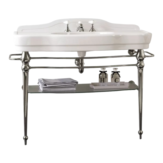
  • Seite 37 Die Glasplatte muss wie Kontaktbereich folgt positioniert sein. zwischen Waschbecked und Wand mit Silikon abdichten. Wenn Sie fertig sind, sollte der Waschtisch wie auf der Abbildung aussehen.
  • Seite 38: Avant De Commencer

    Nous vous remercions d'avoir choisi un produit Devon&Devon et vous prions de lire ce manuel avant d'installer le produit. AVANT DE COMMENCER Vérifier les dispositions d'installation nécessaires avant le montage. Vérifier la présence de tous les articles à l'intérieur de l'emballage grâce à...
  • Seite 39: Liste Des Accessoires

    LISTE DES ACCESSOIRES structure A: Structure métallique de support et étagére porte-objets en verre transparent extra-clair (x1) B: Structure en métal (x1) C: Jambes et structure métallique pour rayon (x2) D: Pieds (x2) E: Vis et bouchons de fixation au mur pour la structure en métal (x8) F: Barres taraudées (x2)
  • Seite 40 LISTE DES ACCESSOIRES lavabo G: Lavabo en céramique (x1) H: Vis et chevilles pour la fixation du lavabo au mur (x4) I: Rondelles en plastique (x4)
  • Seite 41: Montage

    MONTAGE Après avoir sorti de l'emballage les composants de la structure en métal, appuyez la structure métallique (B). Introduisez les deux barres Introduisez la barre taraudée taraudées dans la structure. (F) dans la structure de façon à ce quelle passe aussi à travers le porte-serviettes et que l'écrou se trouve du coté...
  • Seite 42 Introduisez les jambes (C) sur Attachez les pieds (D) en les barres taraudées. les vissant à la partie de la barre taraudée (F) en saillie des jambes. A ce point, la structure métallique assemblée devrait apparaître comme le montre la figure.
  • Seite 43 Voir la position des différents trous de fixation des plaques situés sur la partie arrière de la console. Vérifiez le positionnement de la structure à l'aide d'un niveau dans la direction parallèle ainsi qu'orthogonale au mur.
  • Seite 44 Tracez les trous de fixation des clous au mur. Enlevez la structure et Introduisez les chevilles (D) percez les 8 trous sur la base du (fournies) dans trous, traçage. positionnez à nouveau structure et attachez-la par les vis (fournies).
  • Seite 45 Appuyer le lavabo sur la structure, en cherchant un bon compromis entre l'appui sur la structure et l'appui au mur. Après avoir vérifié la position correcte du lavabo, marquer les quatre points de fixation (indiqués dans l'image située sur la partie arrière).
  • Seite 46 Il est alors possible de retirer le lavabo, de réaliser les trous en respectant les marques faites précédemment. Introduire dans les quatre trous réalisés dans le mur les chevilles et les vis de fixation (H) fournies.
  • Seite 47 Appuyer le lavabo en céramique sur les vis en saillie et sur la structure métallique. Bloquer le lavabo en céramique au moyen des rondelles en plastique (I) fournies.
  • Seite 48 A ce point, dévisser les pommeaux de la structure métallique des jambes. Introduire avec attention le Visser à nouveau tous les rayon en verre. quatre pommeaux du rayon en verre.
  • Seite 49 Le rayon en verre, bien Sceller avec silicone la positionné, devrait apparaître zone de contact entre le lavabo comme le montre la figure ci- et le mur. dessous. A la fin, la console doit se présenter comme surl'illustration ci-contre.
  • Seite 50: Antes De Comenzar

    Les agradecemos por haber elegido un producto Devon&Devon. Les rogamos que lean este manual antes de instalar el producto. ANTES DE COMENZAR Comprobar las predisposiciones para instalación necesarias antes del montaje. Comprobar que todos los artículos se encuentran en el interior del embalaje mediante la lista de contenido (ver página siguiente) y que ninguno de sus componentes presenta defectos visibles.
  • Seite 51 LISTA DE CONTENIDO estructura A: Estructura metálica de soporte y repisa portaobjectos de cristal transparente extraclaro (x1) B: Estructura metálica (x1) C: Patas y estructura metálica para la repisa (x2) D: Pies (x2) E: Tornillos y tacos de anclaje de pared para estructura metálica (x8) F: Barras roscadas (x2)
  • Seite 52 LISTA DE CONTENIDO lavabo G: Lavabo de cerámica (x1) H: Tornillos y tacos de fijación a la pared para lavabo (x4) I: Arandelas de plástico (x4)
  • Seite 53: Instrucciones De Montaje

    INSTRUCCIONES DE MONTAjE Después de haber sacado los elementos de su embalaje, apoye la estructura metálica (B) sobre una superficie de trabajo. Inserte las dos barras Inserte la barra roscada (F) roscadas en la estructura. en la estructura, de modo que atraviese también el toallero y que la tuerca quede por el lado de la estructura.
  • Seite 54 Introduzca las patas (B) en Fije los pies (C) enroscándolos las barras roscadas. en la parte de la barra roscada (F) que sobresale de las patas. La estructura metálica montada debe tener el aspecto indicado en la figura.
  • Seite 55 Se aconseja ver bien la posición de los varios agujeros de fijación de las placas, situados en la parte de atrás de la consola. Controle la posición de la estructura utilizando un nivel en sentido tanto paralelo como ortogonal en la pared.
  • Seite 56 Trace los agujeros de fijación de los tachones. Aparte la estructura y haga Inserte los tacos (D) en 8 agujeros siguiendo el trazado. dotación en los agujeros, vuelva a colocar la estructura y fíjela tornillos, incluidos también en la dotación.
  • Seite 57 Apoye sobre la estructura el lavabo poniendo atención en que quede bien apoyado tanto en la estructura como en la pared. Tras haber comprobado la posición correcta del lavabo, marque los cuatro agujeros de fijación (están indicados en la imagen de abajo, que muestra la parte de atrás).
  • Seite 58 Llegados a este punto, es posible quitar el lavabo, realizar los agujeros en la pared respetando las marcas. Introduzca los tacos y los tornillos de fijación (H) proporcionados en los cuatro agujeros de la pared.
  • Seite 59 Apoye el lavabo de cerámica en los tornillos salientes y en la estructura metálica. Bloquee el lavabo de cerámica utilizando las arandelas de plástico (I) proporcionadas.
  • Seite 60 Desenrosque los pomos de la estructura metálica de las patas. Coloque con atención la Vuelva a enroscar los cuatro repisa de cristal. pomos de la repisa de cristal.
  • Seite 61 La repisa de cristal, bien Selle con silicona la zona colocada, debe tener el aspecto de contacto entre el lavabo y la mostrado en la imagen de más pared. abajo. Al final la consola debe presentar el aspecto mostrado en la imagen.
  • Seite 62: Перед Началом Сборки

    Благодарим за выбор изделия Devon&Devon. Перед установкой внимательно прочитайте настоящую инструкцию. ПЕРЕД НАЧАЛОМ СБОРКИ Перед тем, как приступать к сборке, убедиться в наличии всех элементов структуры. Проверить наличие всех деталей вну три упаковки, в соответствии с Упак овоч ным ли стом, п риведенн ым н а следу ющей странице. Убедит...
  • Seite 63 УПАКОВОЧНЫЙ ЛИСТ ОСНОВНАЯ КОНСТРУКЦИЯ A: Полочка из прозрачного экстраяркого стекла (x1) B: Металлическая конструкция (x1) C: Стойки и металлический каркас для полки (x2) D: Ножки (x2) E: Шурупы с дюбелями для крепления металлической онструкции к стене (x4) F: Стержни с резьбой (х2)
  • Seite 64 УПАКОВОЧНЫЙ ЛИСТ РАКОВИНА G: Раковина керамическая (x1) H: Сантехшпильки с дюбелями для крепления раковины к стене (x4) I: Гайки–шайбы пластмассовые (х4)
  • Seite 65: Инструкция По Сборке

    ИНСТРУКЦИЯ ПО СБОРКЕ 1) После удаления упаковочных материалов, уложите на рабочую плоскость металлическую структуру консоли. Таким же способом вставить 2) Вставить стержень с резьбой в структуру второй стержень с (F) в конструкцию так, чтобы резьбой. он прошел и сквозь втулку полотенцедержателя, причем...
  • Seite 66 Надеть стойки (B) на стержни с Навинтить до упора ножки резьбой. (C) на стержни с резьбой (F), выступающие из надетых на них стоек. 6) В этой стадии, собранный металлический каркас, должен выглядеть как показано на рисунке.
  • Seite 67 7) После этого, обратите внимание на положение крепежных отверстий металлических накладок расположенных на задней стороне консоли. Уровнем проверить параллельность и перпендикулярность положения структуры относительно стены.
  • Seite 68 9) Наметить отверстия для крепления кронштейнов к стене. 10) Отодвинуть конструкцию от Вставить имеющиеся в стены и просверлить 8 отверстия комплекте дюбели (D) в отверстия, по разметке. снова приставить конструкцию к стене и привинтить имеющимися в комплекте шурупами.
  • Seite 69 Установить на конструкцию раковину стараясь достичь равномерного распределения нагрузки на стену и опорную конструкцию. 13) После проверки правильного положения раковины, отметьте положение четырех крепежных отверстий (показанных на нижеприведенном рисунке задней стороны).
  • Seite 70 14) Теперь можно снять раковину, просверлить отверстия в стене в намеченных местах. 15) Вставьте пробки и крепежные винты (Н), вложенные в комплект, в четыре отверстия в стене.
  • Seite 71 16) ) Уложите керамическую раковину на выступающие винты и на металлический каркас. 17) Закрепите керамическую раковину пластмассовыми шайбами (I), вложенными в монтажный комплект.
  • Seite 72 18) После этого отвинтите ручки металлического каркаса стоек. Острожно установите 20) Установите и заверните четыре стеклянную полку. ручки стеклянной полки.
  • Seite 73 Правильно установленная Заполнить пространство стеклянная полка должна между раковиной и стеной выглядеть как приведено следом. силиконом. 23) По завершении работ консоль должна выглядеть как на иллюстрации.
  • Seite 74 Devon & Devon Via Arno, 26 - 50019 Sesto Fiorentino Tel. 0039 055 308350 - Fax 0039 055 375549 www.devon-devon.com email: office@devon-devon.com...

Inhaltsverzeichnis