Alre KTRRB-040.112 Bedienungsanleitung
Quicklinks
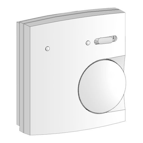
KTRRB-040.112
KTRRB-040.213
KTRRB-040.211
Elektronischer Aufputz-Kühldeckenregler mit Taupunktaufschaltung
Electronic surface type cooling ceiling controller with dew point
Régulateur électronique pour le réglage de plafonds réfrigérants; pilotage en fonction
d'adjonction d'un signal de «point de rosée», pour l'utilisation avec des systèmes
Termostato elettronico per climatizzazione soffitti sopra intonaco con inserzione a mezzo
sensore del punto di rugiada per sistema di tubi a 2 elementi
Sicherheitshinweis
Dieses Gerät darf nur durch eine Elektrofachkraft geöffnet und gemäß dem entsprechenden Schalt-
bild im Gehäusedeckel / auf dem Gehäuse / in der Bedienungsanleitung installiert werden. Dabei
sind die bestehenden Sicherheitsvorschriften zu beachten. Achtung! Der Betrieb in der Nähe von
Geräten, welche nicht den EMV-Richtlinien entsprechen, kann zur Beeinflussung der Gerätefunk-
tionen führen. Nach der Installation ist der Betreiber, durch die ausführende Installationsfirma, in
die Funktion und Bedienung der Regelung einzuweisen. Die Bedienungsanleitung muss für Be-
dien- und Wartungspersonal an frei zugänglicher Stelle aufbewahrt werden. Das Gerät ist
wartungsfrei.
1. Anwendung
Diese Reglertypen wurden speziell zur Heiz- oder Kühlregelung mit Taupunktaufschaltung in
2-Rohrsystemen für Hotel-, Wohn- und Geschäftsräume entwickelt und können bis zu 3 Ventilan-
triebe (24 V, stromlos geschlossen) ansteuern. Für andere, vom Hersteller nicht vorherzusehende
Einsatzgebiete, sind die dort gültigen Sicherheitsvorschriften zu beachten. Eignung hierfür siehe
Punkt 9. Gewährleistung.
2. Funktion
Der KTRRB misst mit einem internen Fühler die Raumtemperatur und aktiviert bei Abweichung
zum eingestellten Sollwert die Heizung bzw. Kühlung. Zur Orientierung bei der Temperatureinstel-
lung besitzen die Reglertypen 040.213 und .211 Schwellpfeile in Rot für „Wärmer" und Blau für
„Kälter". Der Punkt zwischen den Schwellpfeilen stellt den Wohlfühlpunkt dar und entspricht im
Auslieferungszustand ca. 21°C. Dieser Punkt kann mit einem internen Poti um ± 5K (vgl. Punkt 9.)
verändert werden. Mit dem Einstellknopf kann die Wunschtemperatur vom Wohlfühlpunkt aus um
maximal 3 K höher oder niedriger gewählt werden. Der KTRRB-040.112 verfügt über eine °C-Skala
mit einem Einstellbereich von 5 ... 30°C.
2.1 Heiz-Kühl-Umschaltung
Die Heiz-Kühl-Umschaltung wird bei dem Typ KTRRB-040.112 manuell mit dem Heiz-Kühl-Schal-
ter vorgenommen. Die Typen 040.213 und 040.211 verfügen über einen Heiz-Kühl-Umschaltein-
gang für einen externen Kontakt. Kontakt offen = Kühlen, Kontakt geschlossen = Heizen.
2.2. Kühlunterbrechung bei Kondensatbildung
Die Funktion Kühlen kann bei Kondensatbildung durch einen optionalen externen Sensor unter-
brochen werden (vgl. Punkt 5). Der Taupunktsensor muss an den Ort mit der größten Taupunkt-
wahrscheinlichkeit an den Kühlkreislauf montiert werden. Kann dieser Montageort nicht eindeutig
festgelegt werden, besteht die Möglichkeit bis zu 5 Taupunktsensoren parallel an den Regler anzu-
schließen. Vorzugsweise sollten die Taupunktsensoren am in den Raum führenden Zulauf und/
oder im Fensterbereich montiert werden.
2.3 ECO-Betrieb (nicht bei KTRRB-040.211)
Mit dem Energiesparbetrieb „ECO" wird im Heizbetrieb auf einen geringeren und im Kühlbetrieb
auf einen höheren Temperaturwert geregelt. Die Temperaturdifferenz ausgehend vom eingestellten
Sollwert kann intern in einem Bereich von ± 0,5 ... ±2,5 K eingestellt werden. Ausgelöst wird der
ECO-Betrieb durch den externen ECO-Kontakt oder zusätzlich beim KTRRB-040.213 über den
Schalter.
2.4 Leuchtanzeigen:
Lampe links:
rot = Heizung an
grün = Kühlung an
aus = Temperatur erreicht
Lampe rechts:
rot = Kühlunterbrechung wegen Betauung (Kondensatbildung an Kühlleitung)
grün = ECO-Betrieb (nicht bei KTRRB-040.211)
aus = Komfortbetrieb
3. Installation
Der Regler ist zur Montage auf die Wand oder UP-Dose bestimmt und darf nicht direkt Wärme-
oder Kältequellen ausgesetzt werden. Es ist darauf zu achten, dass der Regler auch rückseitig
keiner Fremderwärmung oder -kühlung, z.B. bei Hohlwänden durch Zugluft oder Steigleitungen
ausgesetzt wird. Lässt sich eine ständig gleich bleibende thermische Beeinflussung des Reglers
am Montageort nicht völlig vermeiden, kann der Nullpunkt intern angepasst werden (vgl. Punkt 9.)
Die interne Nullpunkteinstellung darf erst nach Angleichen des Reglers an die Raumtemperatur
(ca. 45 Min.) erfolgen.
Stand 04.2009 (ÄA09/058) JD
im 2-Rohrleitungssystem
signal addition for use with 2-pipe systems
à 2 conduites, modèle pour montage en saillie
D
Safety information!
No persons other than expert electricians only must open this device in due compliance with the
wiring diagram shown in the housing cover / on the housing / represented in the corresponding
operating instructions. Caution! The operation of the controller in the vicinity of other devices that
do not comply with the EMC directives may affect its functions. The company charged with the
installation of the device must, after the completion of the installation works, instruct the user of
the control system into its functions and in how to operate it correctly. These operating instructions
must be kept at a place that can be accessed freely by the operating and/or servicing personnel in
charge. The device requires no attendance.
1. Application
These controller models have been specially devised for the dew point signal addition based con-
trol of the heating and cooling operations performed in 2-pipe systems that exist in hotel rooms,
living spaces and business premises. The devices are able to trigger up to 3 valve drives (24 V,
normally closed). Regarding other applications not to be foreseen by the manufacturer of these
devices, the safety standards concerning these applications need to be followed and adhered to.
Regarding the aptitude of the devices for any such other application, please refer to section 9.
herein (Warranty).
2. Functional description
The controllers of the KTRRB series measure, based on the data that are delivered to them by an
internal sensor, the temperature that exists in the related room and, in the event a deviation of the
actual value with regard to the set value is detected, trigger the activation of the heating or cooling
installation as needed. The controller models KTRRB-040.213 and KTRRB-040.211 have, for orien-
tation purposes, been equipped with a red swelling arrow for "warmer" and with a blue one for
"colder". The point on the scale between the swelling arrows represents the well-being point,
which in the condition as delivered, corresponds to approx. 21°C. An internal potentiometer enab-
les to change this point by ± 5 K (see section 9.). The adjusting knob enables to increase or
decrease the desired temperature as of the well-being point by max. 3 K. The KTRRB-040.112 dis-
poses of a °C scale that enables to cover a setting range from 5 to 30°C.
2.1 Heating / cooling change-over
With the controller model KTRRB-040.112, the changeover between heating and cooling is effected
manually by means of the special heating & cooling switch provided for this purpose. The control-
ler models KTRRB-040.213 and KTRRB-040.211 by contrast dispose of a heating/cooling input for
the triggering via an external contact or via a special flow sensor. Contact opened = cooling,
contact closed = heating.
2.2. Interruption of the cooling operation in the event of the formation of condensate
Optionally, an external sensor can be connected in addition that enables to trigger the interruption
of the cooling mode operation in the event it detects the formation of condensate (see section 5.).
This dew point sensor must be installed at the place within the cooling circuit where the formation
of condensate (dew point) is most likely. If this place of installation cannot be defined clearly, a
total of up to 5 dew point sensors can be connected in parallel to the controller. Preferably, the
required dew point sensors should be installed on the supply line that leads into the related room
and/or should be installed close to the windows.
2.3 Energy economizing function (ECO mode) (does apply to model 040.211)
The operation in ECO or energy economizing mode enables to adjust to a lower temperature value
while heating and to a higher temperature value while cooling. The temperature difference as of
the adjusted set value can be set internally within a range from ± 0.5 to ± 2-5 K. The operation in
ECO mode is triggered via an external ECO contact or, with the controller model KTRRB-040.213,
via the corresponding switch in addition.
2.4 Luminous indications:
Lamp on the left:
Red = heating active
Green = cooling active
OFF = temperature attained
Lamp on the right:
Red = cooling interrupt due to the formation of moisture
(formation of condensate at the cooling line)
Green = ECO mode indication (does not apply to model 040.211)
OFF = operation in comfort mode
3. Mounting / installation
The device is determined for the installation on a wall surface or on an UP box and must not be
exposed directly to any heat- or cold sources. Care must be taken to ensure that it is not exposed to
the influence of heat or cold sources that warm or cool the device at its back (through air flows in
cavity walls or the temperatures radiated by ascending pipelines, f. ex.). In the event the thermal
influencing of the controller at the place of installation cannot be excluded completely, the device
provides the option to adjust the related zero point (see chapter 9.) internally as needed. However,
the internal zero point adjustment may take place only after the controller has adapted itself to the
prevailing room temperature (approx. 45 min.).
1
GB
5 21 399 02

Verwandte Anleitungen für Alre KTRRB-040.112


Inhaltszusammenfassung für Alre KTRRB-040.112
- Seite 1 ± 5 K (see section 9.). The adjusting knob enables to increase or 2.1 Heiz-Kühl-Umschaltung decrease the desired temperature as of the well-being point by max. 3 K. The KTRRB-040.112 dis- poses of a °C scale that enables to cover a setting range from 5 to 30°C.
- Seite 2 à partir du point de bien-être par un taux de dispone di una scala «C» con un campo di regolazione di 5º … 30°C. maximalement 3K. Le modèle KTRRB-040.112 est doté d’une échelle en °C que permet de couvrir une 2.1 Commutazione riscaldamento/raffreddamento étendue de réglage de 5 à...
- Seite 3 0,7A (corrente di cresta max. 0,8A < 150 ms) Puissance de coupure: 0,7A (courant de crête max. 0,8 A <150 ms) Campo regolazione KTRRB-040.112: 5 … 30°C Etendue de réglage KTRRB-040.112: 5 … 30°C Campo regolazione KTRRB-040.213 / .211 Etendue de réglage KTRRB-040.213 /.211 Complessivo: 21°C ±8K...
- Seite 4 è a carico del cliente. Non assumiamo alcuna garanzia al riguardo. Salvo modifiche di ordine tecnico. ALRE-IT Regeltechnik GmbH · Richard-Tauber-Damm 10 · D-12277 Berlin Tel.: +49(0)30/ 399 84-0 · Fax: +49(0)30/ 391 70 05 · mail@alre.de · www.alre.de...