Inhaltsverzeichnis
Werbung
Verfügbare Sprachen
Verfügbare Sprachen
Quicklinks
INSTALLATION MANUAL
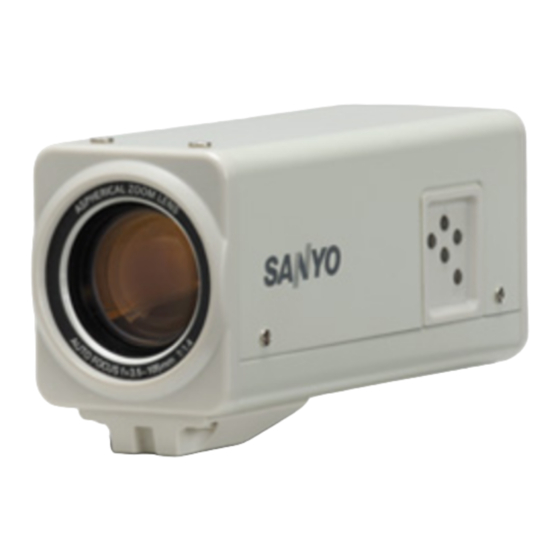
Color CCD Camera
THIS INSTALLATION SHOULD BE MADE BY A QUALIFIED
SERVICE PERSON AND SHOULD CONFORM TO ALL LOCAL
CODES.
Please read this installation manual carefully in order to ensure correct installation. In addition,
be sure to read carefully the electronic manual contained in the supplied CD-ROM to ensure
correct operation of the camera.
● Installation accessory
Clamping core
Installing Camera
Changing the Bracket for Mounting the
Camera
• Make sure to use the longer screws (A) to
secure the bracket.
(B)
Lens cap
(A)
✱ Hole for mounting the camera (Remove the screw before mounting the camera.)
Contents
Information To User. . . . . . . . . . . . . . . . . . . . 1
Parts Names and Functions . . . . . . . . . . . . . 3
Connections. . . . . . . . . . . . . . . . . . . . . . . . . . 5
Features . . . . . . . . . . . . . . . . . . . . . . . . . . . . . 7
How to Perform the Settings in the Menu
Screens . . . . . . . . . . . . . . . . . . . . . . . . . . . . . 9
Learning the Menu Setting Operations . . . 10
Main Specifications. . . . . . . . . . . . . . . . . . . 13
Dimensions . . . . . . . . . . . . . . . . . . Back page
Install the camera in a correct location so
that the intended object can be monitored
properly.
You should also adjust on the monitor
side.
(A)
• If you want to use a commercially available
platform for the camera, select an
appropriate type, taking into consideration
the gross weight of the camera and
platform, and secure it on a firm place.
✱
• Images may blur under extremely bright
lighting; adjust the lighting angle to get
clear images.
(B)
VCC-ZM500P
Werbung
Kapitel
Inhaltsverzeichnis

Verwandte Anleitungen für Sanyo VCC-ZM500P


Inhaltszusammenfassung für Sanyo VCC-ZM500P
-
Seite 1: Inhaltsverzeichnis
INSTALLATION MANUAL Color CCD Camera THIS INSTALLATION SHOULD BE MADE BY A QUALIFIED VCC-ZM500P SERVICE PERSON AND SHOULD CONFORM TO ALL LOCAL CODES. Please read this installation manual carefully in order to ensure correct installation. In addition, be sure to read carefully the electronic manual contained in the supplied CD-ROM to ensure correct operation of the camera. -
Seite 2: Information To User
If water or liquid gets inside the unit, turn off the power immediately and disconnect the power cord, and then consult your dealer or an Authorized Sanyo Service Center. ■ Be careful when handling the unit To prevent damage, do not drop the unit or subject it to strong shock or vibration. - Seite 3 SANYO Electric Co., Ltd. 1-1, Sanyo-cho, Daito City, Osaka 574-8534, Japan This installation manual and the electronic manual are copyrighted by SANYO Electric Co., Ltd. No materials contained in these manuals may be reproduced in any format without the prior...
-
Seite 4: Parts Names And Functions
Parts Names and Functions Rear panel VIDEO OUT connector (BNC type) Outputs video signal. Connect this terminal to the video input terminal of the external device. Control terminals (Push-lock) Used to perform the control functions such as N.C. controlling the camera remotely or inputting/ RS485 outputting alarm. -
Seite 5: Side Panel
Side panel System terminals (Push-lock) Used to connect external system control devices. (a) RS-485 control terminals (Push-lock) Used to perform remote operations of the camera. Connect these terminals to a communication device such as system controller. (b) COM terminal (earth terminal) AC24V/DC12V terminal b For zoom/focus Inputs the power. -
Seite 6: Connections
Do not connect the power cord until all other Connections connections have been completed. ✱1 Alarm Signal Input For details, see “Setting the Alarm Input (ALARM IN)” in the electronic manual contained in the CD-ROM. POWER VIDEO OUT SYNC N.C. CAMERA RS485 LENS... -
Seite 7: Power Supply Connection
Connection with a communication device for remote operation Controller Digital Video Recorder etc. Monitor Connection Power Supply Connection b With AC 24 V • Using different cables from those specified here may attenuate the For the connections, use cables thicker video and/or sync signals and than 18 AWG. -
Seite 8: Features
& You can perform the settings on the camera by Features navigating through the menu screens. Zooming Function Alarm Settings b The camera has a built-in motion sensor. b You can store the zoom and focus & [CAMERA] ⇒ [MOTION] ⇒ [ON] settings of surveillance locations by camera setting number. -
Seite 9: Backlight Compensation
Backlight Compensation White Balance Adjustment b The camera uses 48-part split In addition to the white balance metering areas to compensate the adjustment, you can use the mask backlight condition by metering each patterns to cover extremely bright or area. dark light source in the monitored image You can also select 5-part split so that the white balance adjustment is... -
Seite 10: Screens
How to Perform the Settings in the Menu Screens A Using the buttons on the This manual and the electronic manual which is contained in the supplied camera CD-ROM describe the operations using the buttons on the camera. The optional camera control unit (VAC-70) can be used to perform same operations as the camera. -
Seite 11: Learning The Menu Setting Operations
Learning the Menu Setting Operations Display the main menu. Select a setting value. Setting value SYNC CAMERA LENS Press and hold the button for ALARM about 3 seconds. PRIVACY MASK PASSWORD LANGUAGE OPTION <Main menu> SYNC CAMERA LENS ALARM PRIVACY MASK PASSWORD LANGUAGE OPTION... - Seite 12 Learning the Menu Setting Operations Return to the previous screen. Exit from the menu screen. Select [MENU] – “BACK” at the bottom of the Select [MENU] – “BACK” at the bottom of the screen, use the dc button to select “END”, screen, and press the SET button.
-
Seite 13: Using The Electronic Manual (Cd-Rom)
Using the Electronic Manual (CD-ROM) The menu screens enable you to easily perform setting and adjustment of this camera. By using the electronic manual which is contained in the supplied CD-ROM, you can access extensive information from basic operation to advanced settings and functions, as well as troubleshooting. -
Seite 14: Main Specifications
Main Specifications Television system PAL color standards Image sensor 1/4" interline transfer CCD Effective pixels 752 (Horizontal) x 582 (Vertical) Scanning system 2:1 interlaced, 625 lines Synchronization method Internal synchronization/Line lock (with vertical phase adjustment) Video output 1.0 V (p-p)/75Ω, BNC connector Horizontal resolution 540 TV lines, typical Lowest image illumination... -
Seite 15: Installation De La Caméra
MANUEL D’INSTALLATION Caméra CCD couleurs CETTE INSTALLATION DOIT ETRE EFFECTUEE PAR UNE VCC-ZM500P PERSONNE QUALIFIEE DU SERVICE TECHNIQUE ET DOIT ETRE CONFORME A TOUS LES CODES LOCAUX. Veuillez lire ce manuel d’installation très attentivement afin d’effectuer une installation correcte. Veuillez également lire très attentivement le manuel électronique contenu dans le CD-ROM fourni afin de faire fonctionner la caméra correctement. -
Seite 16: Informations Pour L'utilisateur
Faites attention lors de l’installation près du d’alimentation, puis adressez-vous à votre plafond, dans une cuisine ou dans une chambre revendeur ou à un Centre de service Sanyo des machines, car la température risque de autorisé. monter à un niveau élevé. - Seite 17 SANYO Electric Co., Ltd. 1-1, Sanyo-cho, Daito City, Osaka 574-8534, Japan Le manuel d’installation et le manuel électronique sont protégés par les droits d’auteur de SANYO Electric Co., Ltd. Aucun des éléments contenus dans ces manuels ne peut être reproduit, sous quelque format que ce...
-
Seite 18: Dénomination Et Fonctions Des Pièces
Dénomination et fonctions des pièces Panneau arrière Connecteur VIDEO OUT (type BNC) Émet signal vidéo. Connectez cette connecteur à la borne d’entrée vidéo de l’appareil externe. Bornes de commande à poussoir Pour les fonctions de commande comme la N.C. RS485 commande à... -
Seite 19: Panneau Latéral
Panneau latéral Bornes de système (Verrouillage à poussoir) Sert à connecter des appareils externes de contrôle système. (a) Bornes de commande RS-485 à poussoir Utilisé pour le fonctionnement à distance de la caméra. Reliez ces bornes à un appareil de communication (contrôleur de système par ex.). -
Seite 20: Branchements
Ne branchez pas le cordon d’alimentation tant que Branchements les autres branchements n’ont pas ete effectues. ✱1 Entrée du signal d’alarme Pour tout détail, consultez « Réglage de l’entrée d’alarme (ENT ALARME) » dans le manuel électronique contenu dans le CD-ROM. POWER VIDEO OUT SYNC... -
Seite 21: Connexion De L'alimentation
Connexion avec un appareil de communication pour la commande à distance Contrôleur Enregistreur vidéo numérique, etc. Branchement du moniteur Connexion de l’alimentation b Avec CA 24 V • L’utilisation de câbles autres que ceux spécifiés peut atténuer les signaux vidéo Pour les connexions, utilisez des câbles et/ou sync et réduire la qualité... -
Seite 22: Caractéristiques
& Vous pouvez effectuer les différents réglages sur la Caractéristiques caméra en naviguant à travers les écrans de menu. Fonction zoom Réglages alarme b La caméra est équipée d’un détecteur de b Vous pouvez mémoriser les réglages de zoom et de mise au point des positions mouvement intégré. -
Seite 23: Compensation De Contre-Jour
Compensation de contre-jour Réglage de l’équilibrage des blancs b La caméra utilise des zones de mesure En plus de l’équilibrage des blancs, vous divisées en 48 pour compenser le pouvez utiliser les masques pour couvrir contre-jour en mesurant chaque zone. toute source intense d’ombre ou de lumière Vous pouvez également sélectionner des dans l’image de surveillance pour que... -
Seite 24: Comment Effectuer Les Réglages Dans Les
Comment effectuer les réglages dans les écrans de menu A Avec les boutons de la caméra Ce manuel et le manuel électronique, contenu dans le CD-ROM fourni, décrivent les opérations réalisables avec les boutons de la caméra. La télécommande en option (VAC-70) peut effectuer les mêmes opérations que la caméra. -
Seite 25: Apprentissage Des Opérations De Réglage
Apprentissage des opérations de réglage menu Sélectionnez une valeur de Affichez le menu principal. réglage. Valeur de réglage SYNC Appuyez et maintenez enfoncé le CAMERA LENTILLE bouton pendant environ 3 secondes. ALARME MASQUE M/PASSE <Menu principal> LANGUE OPTION SYNC CAMERA LENTILLE ALARME MASQUE... - Seite 26 Apprentissage des opérations de réglage menu Retournez à l’écran précédent. Sortez de l’écran de menu Sélectionnez [MENU] – « RETOUR » au bas Sélectionnez [MENU] – « RETOUR » au bas de l’écran ; utilisez le bouton dc pour de l’écran, puis pressez le bouton SET. sélectionner «...
-
Seite 27: Utilisation Du Manuel Électronique
Utilisation du manuel électronique (CD-ROM) Les écrans de menu vous permettent de régler et d’ajuster la caméra de façon simple. Le manuel électronique, contenu dans le CD-ROM fourni, vous permet d’accéder à des informations approfondies allant du fonctionnement de base aux fonctions et réglages avancés et à... -
Seite 28: Spécifications Principales
Spécifications principales Système de télévision Standards couleur PAL Capteur d’images CCD transfert interligne 1/4" Pixels effectifs 752 (Horiz.) x 582 (Vert.) Système de balayage 2:1 entrelacé, 625 lignes Mode de synchronisation Synchronisation interne/Line lock (avec ajustement de la phase verticale) Sortie vidéo 1,0 V (p-p)/75Ω, connecteur BNC Résolution horizontale... -
Seite 29: Ccd-Farbkamera
INSTALLATIONSANLEITUNG CCD-Farbkamera DIESE INSTALLATION IST QUALIFIZIERTEM VCC-ZM500P SERVICE-PERSONAL VORBEHALTEN UND MUSS MIT ALLEN LOKALEN GESETZESVORSCHRIFTEN KONFORM SEIN. Lesen Sie bitte diese Anleitung sorgfältig durch, um die einwandfreie Installation sicherzustellen. Lesen Sie außerdem auch die auf der mitgelieferten CD-ROM enthaltene elektronische Anleitung, um die korrekte Bedienung der Kamera zu gewährleisten. -
Seite 30: Informationen Für Den Benutzer
Sie sich an Ihren Händler oder an ein Seien Sie vorsichtig, wenn Sie das Gerät an einer autorisiertes Sanyo-Kundendienstzentrum. Decke, in einer Küche oder in einem Kesselraum installieren, weil die Temperatur stark ansteigen ■ Das Gerät darf nicht geöffnet und es dürfen kann. -
Seite 31: Für Anwender In Der Eu
Stahlgruberring 4, D-81829 München, Germany SANYO Electric Co., Ltd. 1-1, Sanyo-cho, Daito City, Osaka 574-8534, Japan Die Installationsanleitung und die elektronische Anleitung unterliegen dem Urheberrecht der Sanyo Electric Co., Ltd. Die in diesem Handbuch enthaltenen Materialien dürfen in keinem Fall ohne vorherige... -
Seite 32: Bezeichnung Und Funktionen Der Teile
Bezeichnung und Funktionen der Teile Rückseite Video-Ausgangsanschluss (VIDEO OUT: BNC-Buchse) Für die Ausgabe des Videosignals. Verbinden Sie diese Anschluss mit der Videoeingangsbuchse (VIDEO IN) des externen Geräts. N.C. Steuerklemmen (mit Sicherung) RS485 Für die Steuerfunktionen wie beispielsweise die Fernbedienung der Kamera oder die Alarmeingabe/-ausgabe. - Seite 33 Seitenwand Systemklemmen (mit Sicherung) Für den Anschluss von externen Systemsteuergeräten. (a) RS-485 Steuerklemmen (mit Sicherung) Für die Fernbedienung der Kamera. Schließen Sie diese Klemmen an ein Kommunikationsgerät wie beispielsweise ein Systemsteuergerät an. (b) COM-Klemme (Erdungsklemme) b Für Zoom/Scharfeinstellung AC24V/DC12V Klemme Während der Anzeige des Live-Bildes können Für die Stromversorgung.
-
Seite 34: Anschlüsse
Das Netzkabel nicht anschließen, bevor nicht Anschlüsse alle anderen Anschlüsse ausgeführt wurden. ✱1 Alarmeingangsignal Weitere Einzelheiten finden Sie unter „Einstellen des Alarmeingangs (ALARM EIN)“ in der elektronischen Anleitung auf der CD-ROM. POWER VIDEO OUT SYNC N.C. KAMERA RS485 OBJEKTIV EINST ALARM EINST PRIV.MASK. -
Seite 35: Anschluss An Ein Kommunikationsgerät Zur Fernbedienung
Anschluss an ein Kommunikationsgerät zur Fernbedienung Controller Digital-Videorecorder etc. Monitoranschluss Netzanschluss b Mit AC 24 V • Die Verwendung von nicht mit den Spezifikationen konformen Kabeln Verwenden Sie für die Anschlüsse Kabel mit kann die Video- und/oder einem Durchmesser von mehr als 18 AWG. Synchronisationssignalen schwächen und die korrekte Übertragung beeinträchtigen. -
Seite 36: Merkmale
& Sie können die Einstellungen der Kamera über die Merkmale Navigation durch die Menübildschirme vornehmen. Zoomfunktion Alarmeinstellungen b Die Kamera ist mit einem integrierten b Sie können die Zoom- und Scharfeinstellungswerte von Bewegungssensor ausgestattet. & [KAMERA] ⇒ [BEWEGUNGSENSOR] Überwachungsorten nach ⇒... -
Seite 37: Gegenlichtkompensierung
Gegenlichtkompensierung Einstellung des Weißabgleichs b Die Kamera verwendet 48-fach unterteilte Zusätzlich zur Einstellung des Messbereiche, um das Gegenlicht anhand der Weißabgleichs können Sie extrem helle Messung der einzelnen Zonen auszugleichen. oder dunkle Lichtquellen im Für die Messung können Sie auch 5-fach Überwachungsbild auch mit Masken unterteilte Messbereiche (Mitte, links, rechts, abdecken, um den Weißabgleich korrekt... -
Seite 38: Vornehmen Der Einstellungen In Den Menübildschirmen
Vornehmen der Einstellungen in den Menübildschirmen A Mithilfe der Tasten an der Diese Anleitung und die elektronische Anleitung auf der mitgelieferten CD-ROM Kamera umfassen die Beschreibung der mit den Tasten an der Kamera verfügbaren Funktionen. Mit dem optional erhältlichen VAC-70 Kamerasteuergerät können Sie die gleichen Funktionen wie direkt an der Kamera aktivieren. -
Seite 39: Erlernen Der Menüeinstellfunktionen
Erlernen der Menüeinstellfunktionen Erlernen der Wählen Sie einen Einstellwert Menüeinstellfunktionen aus. Einstellwert SYNC KAMERA OBJEKTIV EINST Drücken Sie die Taste und halten Sie ALARM EINST sie circa 3 Sekunden lang gedrückt. PRIV.MASK. EINST KENNWORT EINST SPRACHE EINST OPTION EINST <Hauptmenü> SYNC KAMERA OBJEKTIV... -
Seite 40: Wiederherstellen Der Standardwerte (Werkseinstellungen)
Erlernen der Menüeinstellfunktionen Kehren Sie zum vorherigen Schließen Sie den Bildschirm zurück. Menübildschirm. Wählen Sie [MENUE] – „ZURUECK“ unten im Wählen Sie [MENUE] – „ZURUECK“ unten im Bildschirm, wählen Sie mit den Tasten dc Bildschirm und drücken Sie die SET-Taste. die Option „ENDE“... -
Seite 41: Verwendung Des Elektronischen Handbuchs
Verwendung des elektronischen Handbuchs (CD-ROM) Die Menübildschirme ermöglichen die mühelose Einstellungen und Justierung der Kamera. Durch Verwendung der elektronischen Anleitung auf der mitgelieferten CD-ROM können Sie auf umfassende Informationen von der Grundbedienung bis hin zu erweiterten Einstellungen und Funktionen sowie auf die Fehlersuche zugreifen. Anforderungen für das Betrachten der elektronischen Anleitung Browser: Internet Explorer 6.0 oder höher •... -
Seite 42: Wichtigste Technische Daten
Wichtigste technische Daten Fernsehsystem PAL Farbstandards Bildsensor Interline-Übertragung 1/4"-CCD Effektive Bildpunkte 752 (Horizontal) x 582 (Vertikal) Abtastsystem 2:1 Zeilensprung, 625 Zeilen Synchronisierung Interne Synchronisierung/Line lock (mit vertikaler Phaseneinstellung) Videoausgang 1,0 V (p-p)/75Ω, BNC-Stecker Horizontale Auflösung 540 Zeilen, typisch Mindestbeleuchtung 0,8 lx (F1,4, Verstärkung: Hoch) 0,025 lx (F1,4, 32-facher elektronische Empfindlichkeitssteigerung) Signal-Rausch-Verhältnis 50 dB oder mehr (AGC AUS) - Seite 43 安装手册 摄像头 VCC-ZM500P 本摄像头的安装应由合格的维修人员来执行,且应遵守所有的地方 法规。 为了保证正确的安装,请仔细阅读本安装手册。另外,请务必仔细阅读随附的 CD-ROM 光盘中包含的 电子手册,以保证对摄像头的正确操作。 目录 用户须知 ......1 各部分名称和功能...
-
Seite 44: 用户须知
• 用软布擦拭能去掉壳体上的脏物。 要除去污 异物, 则可能会引起着火、 短路或损伤。 应注意不 垢, 可用软布沾上洗涤剂溶液并拧干后擦拭, 要让雨水、 海水等溅到本机上。 万一水或液体进 然后再用干的软布擦干。 入机内, 请立即关闭电源并脱开电源线, 然后与 • 切勿使用汽油、 涂料稀释剂或其他化学品清洁 销售店或三洋认可的维修中心商谈。 壳体, 否则可能会引起变形和涂漆剥落。 在使 用化学性抹布时, 务必阅读全部随带的使用说 ■ 小心提放本机 明。 切勿将塑料或橡胶材料长时间与机壳接 为了避免损伤, 切勿使本机掉落或遭受强烈的冲 触, 不然会引起损伤或涂漆剥落。 击或震动。 ■ 不要将本机安装在磁场的附近 磁场可能会引起动作不稳定。 本安装手册和电子手册的版权归SANYO Electric Co., Ltd.所有。 未经版权所有者的事先许可,不得以任何形式复制这些手册中包含的任何材料。... -
Seite 46: 各部分名称和功能
各部分名称和功能 后面板 VIDEO OUT(视频输出)连接器(BNC型) 输出视频信号。 将此连接器连接至外部设备的视频输入端子。 控制端子(压锁式) 用于执行控制功能,例如遥控摄像头或输入/输 N.C. 出报警。 RS485 (A) ALARM IN 1/2端子 <报警输入端子> 用于连接检测入侵者的报警设备。 将此端子连接至外部报警开关或红外线传感器 等设备。 (B) ALARM OUT端子 用于连接外部蜂鸣器或指示灯。 POWER指示灯 当检测到报警时,连接至此端子的设备会发出 已检测到报警的通知。 (C) COM端子(接地端子) POWER VIDEO OUT (D) FOCUS端子 N.C. RS485 通过连接外部开关遥控调节焦距。 • DC ± (6 - 12 V), +: 远, –: 近 AC24V (E) ZOOM端子... - Seite 47 侧面板 系统端子(压锁式) 用于连接外部系统控制设备。 (a) RS-485控制端子(压锁式) 用于对摄像头进行遥控操作。 将这些端子连接至系统控制器等通信设备。 (b) COM端子(接地端子) AC24V/DC12V端子 输入电源。 将此端子连接至电源。 b 用于变焦/聚焦 • 当打开摄像头时, POWER指示灯将会变亮, 在观看动像时,可以进行聚焦或变焦操作。 摄像头的系统信息将会在启动屏幕上显示约10 c: 广角 d: 望远 j: 近 l: 远 秒钟。 按一下此按钮即可启动自动聚焦功能。 CAMERA VER X.XX-XX b 用于菜单操作 XXXX PROTOCOL j: 向上移动光标。 ADDRESS l: 向下移动光标。 c: 更改设置值或向右移动光标。...
- Seite 48 在其它连接尚未完成之前,请勿连接电源线。 连接 ✱1 报警信号输入 欲了解详细信息,请参见CD-ROM光盘中包含的 电子手册的 “设置报警输入(ALARM IN)”一 POWER 节。 VIDEO OUT SYNC N.C. CAMERA RS485 LENS ALARM PRIVACY MASK PASSWORD AC24V LANGUAGE BNC类型 OPTION ALARM DC12V ✱2 ALARM IN ALARM OUT ALARM DISPLAY ✱1 防止电磁干扰 (安装附件) b ALARM IN 1 (选定 “1” ) ✱2 所有连接电缆应是最大长度不大于...
- Seite 49 连接通信设备以进行遥控操作 控制器 数字视频录像机等 监视器连接 电源线的连接 b 使用AC 24 V • 如果使用与这些指定类型不同的电 请使用比18 AWG粗的电缆进行连接。 缆,视频和/或同步信号将会被削 弱和受到干扰而无法正常传输。 • 当装置之间的距离很短时,可以使 b 使用DC 12 V 用RG-59U同轴电缆,但不能在管 检查正负极性是否正确。 线或是天线布线中使用。 电缆类型 长度 – RG-59U (3C-2V) 最长250m 最长500m RG-6U (5C-2V) RG-11U (7C-2V) 最长600m 请使用比18 AWG粗的电缆进行连接。...
- Seite 50 功能 & 可通过菜单屏幕导航在摄像头上进行设置。 变焦功能 报警设置 b 摄像头具有一个内置的运动传感器。 b 可以根据摄像头设置编号存储监视位置的 & [CAMERA] ⇒ [MOTION] ⇒ [ON] 变焦和聚焦设置。 & [CAMERA] ⇒ [POSITION] CAMERA 1 CAMERA 2 POSITION POSITION POSITION POSITION POSITION POSITION 未检测到 已检测到 x 1.0 x 3.0 x 3.0 x 3.0 b 通过连接门开关或红外线传感器,可以检...
- Seite 51 背光补偿 白平衡调节 b 摄像头使用了48-分拆分测光区域,可通 除了白平衡调节功能之外,还可以使用掩蔽 过对每个区域进行测光来补偿背光条件。 样式在被监控图像中覆盖极亮或极暗的光 也可以选择5-分拆分测光区域(中、左、 源,这样就可以正确地配置白平衡调节功 右、上、下)进行测光。 能。 & & [CAMERA] ⇒ [BLC] ⇒ [MULT] or [CAMERA] ⇒ [WHITE BALANCE] ⇒ [ATW] ⇒ [MASKING] [CENT] b 可以掩蔽不想对其进行测光的测光区域。 & [CAMERA] ⇒ [BLC] ⇒ [MASK] 隐私掩蔽 隐私掩蔽可隐藏被监控图像的某个部分,因 此可用来保护隐私。 ( 最多 4 个掩蔽位置 ) &...
-
Seite 52: 如何在菜单屏幕中进行设置
如何在菜单屏幕中进行设置 本手册和随附的 CD-ROM 光盘中包含的电子 A 使用摄像头上的按钮 手册说明了使用摄像头按钮的操作。 可使用任意的摄像头控制器 (VAC-70) 与摄像 头进行相同的操作。 欲了解详细信息,请参阅摄像头控制器的说明 手册。 1 显示主菜单。 按住SET按钮3秒钟以上即可显示 主菜单。 2 在菜单设置操作中移动光标。 3 切换菜单屏幕。 4 进行聚焦或放大/缩小操作。 在自动聚焦功能激活时,可以使用 这些按钮进行聚焦操作。 j: 近 l: 远 d: 广角 c: 望远 B 使用VAC-70摄像头控制器 (可选购)进行遥控设置... -
Seite 53: 了解菜单设置操作
了解菜单设置操作 显示主菜单。 选择设置值。 设置值 SYNC CAMERA LENS 按住此按钮约3秒钟。 ALARM PRIVACY MASK PASSWORD LANGUAGE OPTION <主菜单> SYNC CAMERA LENS ALARM PRIVACY MASK PASSWORD LANGUAGE OPTION 按dc按钮即可切换设置值。 PRESET MENU 转到下一屏幕。 选择菜单项。 选择了具有 y 标记的菜单项并按下 SET 按钮之 菜单项 光标 后,将会出现包含高级选项的子菜单屏幕。 SYNC SYNC CAMERA CAMERA LENS LENS... - Seite 54 了解菜单设置操作 返回前一屏幕。 从菜单屏幕中退出。 选择屏幕底部的 [MENU] - “BACK” ,然后按 选择屏幕底部的 [MENU] - “BACK” ,再使用 下 SET 按钮。 dc 按钮选择 “END” ,然后按下 SET 按钮。 IRIS AUTO PRESET WHITE BALANCE MENU BACK SHUTTER APERTURE GAMMA 0.45 MOTION POSITION PRESET MENU BACK PRESET MENU 恢复默认值(出厂设置) ●...
-
Seite 55: 使用电子手册(Cd-Rom光盘)
使用电子手册(CD-ROM光盘) 通过菜单屏幕,您可以轻松地对本摄像头进行设置和调节。 通过使用随附的 CD-ROM 光盘中包含的电子手册,您可以获得从基本操作到高级设置和功能以及故障 排除等方面的广泛信息。 查看电子手册的要求 浏览器:Internet Explorer 6.0以上 • 请确认已启用了JavaScript和Cookie。 • 如要使用搜索功能,还需启用ActiveX控件。 将CD-ROM光盘插入到计算机的CD驱动器中,然后双击 “ ”图标。 选择摄像头型号(屏幕1)。 (屏幕1) (屏幕2) 选择所需的语言(屏幕2)。 电子手册开启。 单击 “Open this manual” (打开本手册)。 在屏幕左侧的菜单中单击需要获得相关 信息的项目。 此时将会打开一个应用页面。 • 查看每个用法的菜单设置步骤 在屏幕左侧的菜单上单击 “设置菜单指导” 。 • 查看术语表的定义 在屏幕左侧的菜单上单击 “术语表” 。 •... -
Seite 56: Dimensions (Abmessungen)
56 x 64 x 150 (mm) 重量 约为540g Microsoft、 ActiveX和Internet Explorer是Microsoft Corporation在美国和其他国家 (地区)的注册商标或商标。 Adobe Reader是Adobe Systems Incorporated的商标。 本手册中的所有其他品牌和产品名称均是各自所有者的注册商标或商标。 Dimensions 56 (2.2) (0.1) 147 (5.8) 10 (0.4) Unit: mm (inch) 1/4"-20UNC SANYO Electric Co., Ltd. 1AC6P1P3338-- L5CN2/XE (0508KP-HS) Printed in China...