
Verwandte Anleitungen für Feig Electronic OBID i-scan ID ISC.LR200 series

Inhaltszusammenfassung für Feig Electronic OBID i-scan ID ISC.LR200 series
- Seite 1 MONTAGE ® OBID i-scan INSTALLATION ID ISC.LR200 (deutsch / english) final public (B) 2002-10-18 M00601-4de-ID-B.DOC...
- Seite 2 ® OBID i-scan Montage ID ISC.LR200 FEIG ELECTRONIC GmbH Seite 2 von 50 M00601-4de-ID-B.DOC...
- Seite 3 ® OBID i-scan Montage ID ISC.LR200 deutsche Version ab Seite 4 english version from page 28 FEIG ELECTRONIC GmbH Seite 3 von 50 M00601-4de-ID-B.DOC...
- Seite 4 Hinweise jederzeit dankbar. Die in diesem Dokument gemachten Installationsempfehlungen gehen von günstigsten Rahmenbedingun- gen aus. FEIG ELECTRONIC GmbH übernimmt keine Gewähr für die einwandfreie Funktion in systemfrem- den Umgebungen. FEIG ELECTRONIC GmbH übernimmt keine Gewährleistung dafür, dass die in diesem Dokument enthal- tenden Informationen frei von fremden Schutzrechten sind.
-
Seite 5: Inhaltsverzeichnis
3.8. X9: RS485-Schnittstelle....................18 3.9. X10: RS232-Schnittstelle....................19 4. Bedien- und Anzeigeelemente 4.1. LED ..........................20 4.2. Taster / Schalter......................21 5. Inbetriebnahme 5.1. Schnittstellenkonfiguration mittels Jumper ..............22 5.2. Adresseinstellung für Busbetrieb ................. 23 FEIG ELECTRONIC GmbH Seite 5 von 50 M00601-4de-ID-B.DOC... - Seite 6 ® OBID i-scan Montage ID ISC.LR200 6. Funkzulassungen ID ISC.LRM200 6.1. Europa (CE)........................24 6.2. USA (FCC) ........................24 7. Technische Daten FEIG ELECTRONIC GmbH Seite 6 von 50 M00601-4de-ID-B.DOC...
- Seite 7 16 A, USA 15 A) besonders zu berücksichtigen. • Der Kühlkörper auf der Gehäuserückseite kann sich während des Betriebes stark erwärmen. • Für den Anschluß von Peripheriegeräten sind mehradrige Leitungen zu verwenden. FEIG ELECTRONIC GmbH Seite 7 von 50 M00601-4de-ID-B.DOC...
-
Seite 8: Leistungsmerkmale Des Readers Id Isc.lr200-A/B
Schnittstelle betrieben werden. Die Adresse des Readers kann dabei per Software oder über 3 DIP-Schalter vorgegeben werden. 2.2. Verfügbare Readertypen Folgende Readertypen sind z.Z. verfügbar: Readertyp Beschreibung ID ISC.LR200-A Anschluß für eine Basisantenne ID ISC.LR200-B Anschluß für eine Basis- und eine Ergänzungsantenne FEIG ELECTRONIC GmbH Seite 8 von 50 M00601-4de-ID-B.DOC... -
Seite 9: Lieferumfang
Spannungsversorgung) 2 x EMV-Ringkernferrit ∅ 28mm x 20 mm (2 x Antennenzuleitung) 2 x Duo-Aderendhülse (2 x 1,5 mm², schwarz) 2 x Duo-Aderendhülse (2 x 2,5 mm², blau) 6 x Kurzschlußbrücke (Jumper) FEIG ELECTRONIC GmbH Seite 9 von 50 M00601-4de-ID-B.DOC... -
Seite 10: Montage Und Anschluß
M 12 3,5 – 7 Ausgänge M 16 4,5 – 10 Anschlußkabel Basisantenne M 12 3,5 – 7 Eingänge M 16 4,5 – 10 Anschlußkabel Ergänzungsantenne M 12 3,5 – 7 Schnittstelle (RS232/RS485) FEIG ELECTRONIC GmbH Seite 10 von 50 M00601-4de-ID-B.DOC... -
Seite 11: Anschlußklemmen Und Bedienelemente
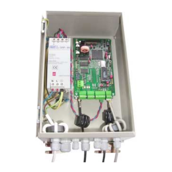
® OBID i-scan Montage ID ISC.LR200 3.1. Anschlußklemmen und Bedienelemente + + - - Obere Leiterplatte J401 J400 Untere Leiterplatte Bild 3.1-1: Draufsicht : Netzteil, obere und untere Leiterplatte FEIG ELECTRONIC GmbH Seite 11 von 50 M00601-4de-ID-B.DOC... -
Seite 12: Antennenanschluß
10 cm betragen (siehe Bild 3.2.-1). • Beim Anschluß einer Antenne ist darauf zu achten, daß diese die zulässigen Grenzwerte der nationalen Vorschriften bezüglich Funkanlagen nicht überschreitet. Bild 3.2.-1: Antennenkabel mit EMV-Ringkernferrit FEIG ELECTRONIC GmbH Seite 12 von 50 M00601-4de-ID-B.DOC... -
Seite 13: Versorgungsspannung
Für den Schutzleiter-Anschluß muß die entsprechende grün-gelbe Ader der Zulei- tung (1) mit der vorkonfektionierten grün-gelben Leitung (2) zusammen in eine der beigefügten Duo-Aderendhülsen gekrimpt werden. Der Anschluß erfolgt an der entsprechenden Schutzleiterklemme des Netzteils. FEIG ELECTRONIC GmbH Seite 13 von 50 M00601-4de-ID-B.DOC... -
Seite 14: X7: Eingänge (Optokoppler)
5 V ... 10 V 270 Ω 11 V ... 15 V 560 Ω 16 V ... 20 V 820 Ω 21 V ... 24 V Tabelle 3.4-1: Benötigter externer Vorwiderstand R FEIG ELECTRONIC GmbH Seite 14 von 50 M00601-4de-ID-B.DOC... -
Seite 15: X6: Ausgänge (Optokoppler)
Verpolung oder Überlastung der Ausgänge führt zu deren Zerstörung. • Die Ausgänge sind nur zum Schalten ohmscher Lasten vorgesehen. ID ISC.LRM200 O1-C ext. O1-E O2-C ext. O2-E Bild 3.5-1: Interne und mögliche externe Beschaltung der Optokopplerausgänge FEIG ELECTRONIC GmbH Seite 15 von 50 M00601-4de-ID-B.DOC... -
Seite 16: X11: Relais
• Die Relaisausgänge sind nur zum Schalten ohmscher Lasten vorgesehen. Im Falle einer induktiven Last sind die Relaiskontakte durch eine externe Schutzbeschaltung zu schüt- zen. ID ISC.LRM200 ext. Bild 3.6-1: Interne und mögliche externe Beschaltung des Relaisausgangs FEIG ELECTRONIC GmbH Seite 16 von 50 M00601-4de-ID-B.DOC... -
Seite 17: X18: Anschluß Externer Diagnose-Led
Bild 3.7-1: Anschluß externer LEDs an X18 Hinweis: • Die Ausgänge an X18 sind nur zum Schalten einer externen LEDs vorgesehen. Überlas- tung der Ausgänge durch andere Lasten kann zu deren Zerstörung führen. FEIG ELECTRONIC GmbH Seite 17 von 50 M00601-4de-ID-B.DOC... -
Seite 18: X9: Rs485-Schnittstelle
RS485 – (A -) 4xxG RS485 – GND 422Y n.c. 422Z n.c. 422G n.c. ID ISC.LRM200 RS485 - (B+) RS485 - (A-) RS485 - GND n.c. n.c. n.c. Bild 3.8-1 : Anschlußbelegung der RS485-Schnittstelle FEIG ELECTRONIC GmbH Seite 18 von 50 M00601-4de-ID-B.DOC... -
Seite 19: X10: Rs232-Schnittstelle
Hierzu ist das Kabel mindestens acht mal, eng anliegend durch den EMV- Ringkernferrit zu schleifen. Der Abstand zwischen Readeranschluß und Ringkern sollte dabei maximal 10 cm betragen (siehe Bild 3.8.-2). Bild 3.9.-2: Schnittstellenzuleitung mit EMV-Ringkernferrit FEIG ELECTRONIC GmbH Seite 19 von 50 M00601-4de-ID-B.DOC... -
Seite 20: Bedien- Und Anzeigeelemente
Leuchtet während der Reader-Initialisierung nach dem Ein- schalten bzw. nach einem Reset. Leuchtet bei einem Fehler im RF-Teil des Readers. Der Feh- lertyp kann per Software über die RS232/RS485-Schnittstelle ausgelesen werden Tabelle 4.1-1: Konfiguration der LED FEIG ELECTRONIC GmbH Seite 20 von 50 M00601-4de-ID-B.DOC... -
Seite 21: Taster / Schalter
Kurzzeichen Beschreibung Reset-Taster 1 - 3: Adresseinstellung Datenbus (0 ... 7) nicht benutzt Hinweis : Für die Einstellung der Busadresse über S2 muß der Reader auf die Softwareadresse "0" eingestellt sein (Werkseinstellung). FEIG ELECTRONIC GmbH Seite 21 von 50 M00601-4de-ID-B.DOC... -
Seite 22: Inbetriebnahme
RS485 - A ⇔ RS485 - B Hinweis: Der gleichzeitige Betrieb von RS232 und RS485 Schnittstelle ist nicht möglich. J405 RS485 - B+ J403 RS485 - A- J407 Jumper der RS485 Schnittstelle FEIG ELECTRONIC GmbH Seite 22 von 50 M00601-4de-ID-B.DOC... -
Seite 23: Adresseinstellung Für Busbetrieb
Die Adressvergabe erfolgt über den Host-Rechner. Mit Hilfe der Software können dem Reader die Adressen "0" bis "253" zugewiesen werden. Hinweis: Da alle Reader werksseitig die Adresse 0 eingestellt haben, müssen sie nacheinander ange- klemmt und konfiguriert werden. FEIG ELECTRONIC GmbH Seite 23 von 50 M00601-4de-ID-B.DOC... - Seite 24 ID ISC.ANT800/600A mit Power Splitter ID ISC-ANT PS. Zur Einhaltung der Grenzwerte nach FCC 47 CFR CH. I Part 15 ist der Reader ID ISC.LRM200 auf eine HF-Ausgangsleistung von maximal 1,5 W einzustellen. FEIG ELECTRONIC GmbH Seite 24 von 50 M00601-4de-ID-B.DOC...
- Seite 25 - 2 Optokoppler 24 V DC / 2 A - 1 Relais ( 1 x Wechsler) • Eingänge – 2 Optokoppler max. 24 V DC/ 20 mA • Schnittstellen RS232 und RS485 (wahlweise einstellbar) FEIG ELECTRONIC GmbH Seite 25 von 50 M00601-4de-ID-B.DOC...
- Seite 26 • Schock EN60068-2-27 Beschleunigung : 30 g Angewendete Normen • Zulassung Funk - Europa EN 300 330 - USA FCC 47 CFR Part 15 • EN 300 683 • Sicherheit EN 60950 FEIG ELECTRONIC GmbH Seite 26 von 50 M00601-4de-ID-B.DOC...
- Seite 28 ELECTRONIC GmbH does not give any guarantee promise for perfect function in cross environments. FEIG ELECTRONIC GmbH assumes no responsibility for the use of any information contained in this manual and makes no representation that they free of patent infringement. FEIG ELECTRONIC GmbH does not convey any license under its patent rights nor the rights of others.
- Seite 29 10.9. X10: RS232 interface ....................43 11. Control and display elements 11.1. LED ..........................44 11.2. Buttons / switches......................45 12. Initialization 12.1. Interface configuration via jumper ................46 12.2. Address configuration for bus mode ................47 FEIG ELECTRONIC GmbH Page 29 of 50 M00601-4de-ID-B.DOC...
- Seite 30 ® OBID i-scan Installation ID ISC.LR200 13. Radio Approvals ID ISC.LRM200 13.1. Europe (CE)........................48 13.2. USA (FCC) ........................48 14. Technical Data Page 30 of 50 FEIG ELECTRONIC GmbH...
- Seite 31 Europe 16 A, USA 15 A) have to be considered in particular. • The dissipator on the back of the casing may heat severely during operation. • For connecting auxiliary equipment multiconductor cable has to be used. FEIG ELECTRONIC GmbH Page 31 of 50 M00601-4de-ID-B.DOC...
-
Seite 32: Features Of The Id Isc.lrm200-A/B Reader Module
9.2. Available reader types The following reader types are available at the moment: Reader type description ID ISC.LR200-A connection for a basic antenna ID ISC.LR200-B connection for a basic- and a complementary antenna Page 32 of 50 FEIG ELECTRONIC GmbH... -
Seite 33: Delivery
2 x EMC ring core ∅ 28mm x 20 mm (2 x Antenna line) 2 x Duo wire end ferrule (2 x 1,5 mm², blau) 2 x Duo wire end ferrule (2 x 2,5 mm², schwarz) 6 x Jumper FEIG ELECTRONIC GmbH Page 33 of 50 M00601-4de-ID-B.DOC... -
Seite 34: Mounting And Connection
M 16 4,5 – 10 connection casbles of basic antenna M 12 3,5 – 7 inputs M 16 4,5 – 10 connection cable of complementary antenna M 12 3,5 – 7 interface (RS232/RS485) Page 34 of 50 FEIG ELECTRONIC GmbH... -
Seite 35: Connection Terminals And Operational Control Elements
OBID i-scan Installation ID ISC.LR200 10.1. Connection terminals and operational control elements + + - - Obere Leiterplatte J401 J400 Untere Leiterplatte Fig. 10.1-1: top view, power unit, upper and lower board FEIG ELECTRONIC GmbH Page 35 of 50 M00601-4de-ID-B.DOC... -
Seite 36: Antenna Connection
10 cm (see Fig. 9.2.-1). • When connecting an antenna, ensure that it does not exceed the permissible limits pre- scribed by the national regulations for radio frequency devices. Fig. 10.2.-1: Antenna line with EMC ring cores Page 36 of 50 FEIG ELECTRONIC GmbH... -
Seite 37: Supply Voltage
(1) must be crimped together with the preassembled green/yellow line (2) in one of the supplied duo wire end ferrules. The connection is then made at the corresponding protection ground terminal of the power sup- ply. FEIG ELECTRONIC GmbH Page 37 of 50 M00601-4de-ID-B.DOC... -
Seite 38: X7: Inputs (Optocoupler Isolated)
5 V ... 10 V 270 Ω 11 V ... 15 V 560 Ω 16 V ... 20 V 820 Ω 21 V ... 24 V Table 10.4-1: Required external dropping resistor R Page 38 of 50 FEIG ELECTRONIC GmbH... -
Seite 39: X6: Output (Optocoupler Isolated)
Reversing the polarity or overloading the outputs will destroy the unit. • The outputs are designed to switch resistive loads only. ID ISC.LRM200 O1-C ext. O1-E O2-C ext. O2-E Fig. 10.5-1: Internal and possible external wiring of the optocoupler outputs FEIG ELECTRONIC GmbH Page 39 of 50 M00601-4de-ID-B.DOC... -
Seite 40: X11: Relay
• The relay outputs are designed to switch resistive loads only. If using an inductive load, the relay contacts must be protected by means of an external protection circuit. ID ISC.LRM200 ext. Fig. 10.6-1: Internal ans possible external wiring of the relay output Page 40 of 50 FEIG ELECTRONIC GmbH... -
Seite 41: X18: Connection Of External Diagnostic Led
LEDs Fig. 10.7-1: Connection of external LEDs Note: • The outputs of X18 are designed to switch an external LEDs only. Overloading the out- puts by other loads will destroy the unit FEIG ELECTRONIC GmbH Page 41 of 50 M00601-4de-ID-B.DOC... -
Seite 42: X9: Rs485 Interface
RS485 – (A -) 4xxG RS485 – GND 422Y n.c. 422Z n.c. 422G n.c. ID ISC.LRM200 RS485 - (B+) RS485 - (A-) RS485 - GND n.c. n.c. n.c. Fig. 10.8-1 : Configuring the RS485 interface Page 42 of 50 FEIG ELECTRONIC GmbH... -
Seite 43: X10: Rs232 Interface
8 turns. The distance between the Reader termi- nation and the ring core should be maximum 10 cm. Fig. 9.9.-2: Interface line with EMC ring cores FEIG ELECTRONIC GmbH Page 43 of 50 M00601-4de-ID-B.DOC... -
Seite 44: Control And Display Elements
Comes on during Reader initialization after power-up or after a reset. Comes on to indicate an error in the RF section of the Reader. The error type can be read out via software on the RS232/RS485 interface Table 11.1-1: LED configuration Page 44 of 50 FEIG ELECTRONIC GmbH... -
Seite 45: Buttons / Switches
1 - 3: Setting data bus addresses (0 ... 7) not used Note : To set the bus address using S2, the Reader must be set to software address „0“ (factory setting). FEIG ELECTRONIC GmbH Page 45 of 50 M00601-4de-ID-B.DOC... -
Seite 46: Initialization
RS485 - A ⇔ RS485 - B Note: It is not possible to operate both RS232 and RS485 at the same time. J405 RS485 - B+ J403 RS485 - A- J407 Jumpers for RS485 interface Page 46 of 50 FEIG ELECTRONIC GmbH... -
Seite 47: Address Configuration For Bus Mode
"0" to "254" can be allocated to the reader. NOTE: As all readers have been set to the address 0 by the manufacturer, they have to be connected and configured on after the other. FEIG ELECTRONIC GmbH Page 47 of 50 M00601-4de-ID-B.DOC... - Seite 48 ID ISC.ANT800/600A mit Power Splitter ID ISC-ANT PS. To maintain the limit values as per FCC 47 CFR CH. I Part 15, the ID ISC.LRM200 Reader must be set to a HF output power of maximum 1.5 W. Page 48 of 50 FEIG ELECTRONIC GmbH...
- Seite 49 24 V DC / 2 A - 1 relay ( 1 x center-zero relay) • inputs - 2 optocouplers max. 24 V DC/ 20 mA • interface RS232 and RS485 (optionally adjustable) FEIG ELECTRONIC GmbH Page 49 of 50 M00601-4de-ID-B.DOC...
- Seite 50 • shock resistance EN60068-2-27 acceleration : 30 g Employed standards • radio authorization - Europe EN 300 330 - USA FCC 47 CFR Part 15 • EN 300 683 • security EN 60950 Page 50 of 50 FEIG ELECTRONIC GmbH...