Block ESG 6 Gebrauchsanleitung
Einschaltstrombegrenzer
Verfügbare Sprachen
Verfügbare Sprachen
Safety and User Information
Congratulations to the ownership of this high quality product. A
long life expectancy is assured if used in the described manner
and correct application. As with all technical products, a hazard
to health or equipment can exist if improperly used, an un-
authorized removal of necessary covers, an incorrect in-
stallation or an incorrect operation is present. Follow these in-
structions and adhere to the generally accepted rules of tech-
nology. Installation and setting-up should only be carried out by
qualified personal.
Packing
Please check carefully the equipment immediately after receipt,
for transport damage as deformation, breakage or loose parts.
Any damage should be reported without delay to the transport
carrier, even if no apparent damage to external packing is vi-
sible.
Storage
Permitted Storage Temperature -40°C...+85°C
Permitted Humidity
30%...80% relative humidity
Residual humidity is not per-
mitted.
Extended Storage
Equipment containing capa-
citors: should be connected
to the mains supply for at
least 5 minutes every two
years.
Installation and Operation
This equipment is protected against improper use. The contact
with electrical components and terminals should be avoided.
The product description, the technical information in our main
catalogue and the marking on the equipment are to be ob-
served. The installation must be carried out according to the
prevailing local conditions, prevailing safety standards, national
accident preventions and the generally accepted rules of tech-
nology.
Maintenance and Servicing
This equipment usually requires no special maintenance, how-
ever (depending on the protection index) it must be protected
against aggressive chemicals, moisture, dust and radiation.
Servicing is only permitted under the terms and conditions of
these operating instructions. Nevertheless should a failure
occur, please return the equipment to us for repair. Please give
us the following information: Type of fault, accompanying symp-
toms (operating conditions), your own speculation upon the
cause of the failure, previous unusual conditions, etc.
Disposal
Please observe the current regulations and dispose according
to type of material, e.g. as electronic scrap (printed circuit
boards), plastics (housing), steel, copper, etc.
6
Amendments
We have produced this documentation with the utmost care; how-
ever no guarantee in terms of correctness and completeness can
be given. The adoption of this information in an application must
be individually checked. The technical details describe the product
features without guaranteeing these. This product is subject to
changes that serve the technical advancement.
Description and Application
On physical condition, during power-up of certain loads, the auto-
matic circuit breaker or the motor circuit switch could shut off. The
Inrush Current Limiter prevents this. It can power-up and supply a
load up to max. 16A. The Inrush Current Limiter is insetted in the
load line. It has an intrinsic resistance (limiting resistance) of typ.
7.8 Ω, which is in series connection with the load. Therefore it can
flow an inrush current of max. 29.5A at 230Vac (because of the im-
pedances of mains and loads, the real inrush current is usually lo-
wer). Normally the switch-on peaks are decreased after some pe-
riods and the build-in power-relay bridges the intrinsic resistance of
the Inrush Current Limiter. Now the load is directly connected with
the mains. The Inrush Current Limiter operates mainly current-
leaded and partly time-leaded, i.e. the load current is continuously
controlled. Below a minimum load of typ. 20W, open-circuit is de-
tected and the limiting resistance is switched in the circuit perma-
nently. On higher wattage the limiting resistance is bridged; in this
case the inrush current cannot be limited. The period of inrush
current limiting is max. 300ms; depending on the load it will
reduced to min. 60ms. At the power-up moment of the Inrush
Current Limiter there is a defined limiting time of 150ms.
Standards
The requirements for CE conformity are given and the equipment
is CE marked. The ESG 6 is UL recognized according UL 60730-1.
Operation Information
The adequate cooling of the equipment should not be effected and
the air circulation must be guaranteed. Due to the protection index,
the use of the equipment is only permitted in dry areas.
Connection Information
The mains input wires of the load must be connected via the
Inrush Current Limiter with the mains. For save operation a rated
voltage not below 99Vac in the moment of turn-on the load is
required. More loss of voltage could cause an overload and would
result an irreparable damage to the Inrush Current Limiter by
activating the internal thermal fuse!
Connection
Before connection the Inrush Current Limiter to mains, check the
correct supply voltage (also see the marking on the equipment).
Fuse
The equipment is internally protected with a non-resettable thermal
fuse. If this fuse is switched off, with the utmost probability an un-
suitable mains supply is present (see Connection Information).
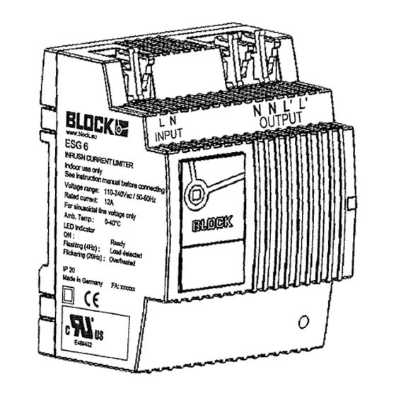
LED
The green LED indicates the operating status:
on
:
ready
flashing
:
load detected
flickering
:
overheated
7
Technical Specification
Nominal Voltage
: 230Vac
Voltage Range
: 110Vac...240Vac ± 10%
Nominal Frequency
: 50Hz...60Hz
Nominal Current
: up to 16A effective
up to 12A effective UL-rated
Ambient Temperature : -25°C ... +40°C
0°C...+40°C (UL rating)
Intrinsic Resistance
: 7,8Ω ±5%
at the power-up moment
Switching Time
: bridging after approx. 60ms...300ms
(3...15 periods at 50Hz) depending on load
Input Connections (Input: L , N )
2-pole black, METZ Connect ST055
Type of wires
: single-wire
Cross Section
: AWG 28 - AWG12 / 0.08 - 2.5mm²
Stripped length : 0.24inch / 6mm
Output Connections (Output: N , N , L' , L' )
4-pole black, METZ Connect ST055
Type of wires
: single-wire
Cross Section
: AWG 28 - AWG12 / 0.08 - 2.5mm²
Stripped length : 0.24inch / 6mm
Protection Class
: II
Over Voltage Category : III
Pollution Degree
: PD 2
Protection Index
: IP20
●
Safety
:
build-in, non-exchangeable thermal fuse
in the load circuit
●
temperature controller bridges limiting
resistance at overload
Dimensions/ Weight
W x H x D
: 54 x 89 x 59mm
Weight
: 170g
8
Block Transformatoren-Elektronik
GmbH
Max-Planck-Straße 36-46
27283 Verden
Germany
Phone: +49 4231 678 0
Fax: +49 4231 678 177
www.block.eu
sales@block.eu
Gebrauchsanleitung
Einschaltstrombegrenzer
ESG 6
Instruction Manual
Inrush Current Limiter
ESG 6
|
EN 61000-6-1
UL 60730-1
EN 61000-6-3
CSA E60730-1:13
EN 61000-3-2
EN 61000-3-3
EN 60730-1
Made in Germany
Zeichnung-Nr. / Drawing-No.: Z711103001 /g
Teile-Nr. / Part-No.: #005-0239
Änderungen vorbehalten / subject to change without notice
1

Verwandte Anleitungen für Block ESG 6

Inhaltszusammenfassung für Block ESG 6
- Seite 2 Das Gerät entspricht den gesetzlichen Anforderungen und Normen ● Sicherheit integrierte, nicht auswechselbare zur CE-Konformität und trägt das CE-Zeichen. Der ESG 6 besitzt Das Gerät bedarf in der Regel keiner besonderen Wartung, es ist Temperatursicherung im Lastkreis eine UL-Zulassung nach UL 60730-1.