AFRISO PrimoTherm 180-2 DN 25 RTA Betriebsanleitung
Heizungspumpengruppe
Inhaltsverzeichnis
Verfügbare Sprachen
Verfügbare Sprachen
Quicklinks
Betriebsanleitung
Heizungspumpengruppe
PrimoTherm®
Typ:180-2 DN 25 RTA mit 3-Wege-Mischer und Stellmotor
Typ:180-3 DN 25 RTA mit thermischen Festwertventil (+45 °C/+55 °C/+60 °C)
Copyright 2017 AFRISO-EURO-INDEX GmbH. Alle Rechte vorbehalten.
Lindenstraße 20
74363 Güglingen
Telefon +49 7135-102-0
Service +49 7135-102-211
Telefax +49 7135-102-147
info@afriso.com
Version: 04.2017.0
www.afriso.com
ID: 900.000.0659
Inhaltsverzeichnis
Fehlerbehebung

Verwandte Anleitungen für AFRISO PrimoTherm 180-2 DN 25 RTA

Inhaltszusammenfassung für AFRISO PrimoTherm 180-2 DN 25 RTA
- Seite 1 Betriebsanleitung Heizungspumpengruppe PrimoTherm® Typ:180-2 DN 25 RTA mit 3-Wege-Mischer und Stellmotor Typ:180-3 DN 25 RTA mit thermischen Festwertventil (+45 °C/+55 °C/+60 °C) Copyright 2017 AFRISO-EURO-INDEX GmbH. Alle Rechte vorbehalten. Lindenstraße 20 74363 Güglingen Telefon +49 7135-102-0 Service +49 7135-102-211 Telefax +49 7135-102-147 info@afriso.com...
- Seite 2 Über diese Betriebsanleitung Über diese Betriebsanleitung Diese Betriebsanleitung beschreibt die Heizungspumpengruppe zur Rück- lauftemperaturanhebung bei Festbrennstoff-Kesseln PrimoTherm® „180-2 DN 25 RTA / 180-3 DN 25 RTA“ (im folgenden auch „Produkt“). Diese Betriebsanleitung ist Teil des Produkts. • Sie dürfen das Produkt erst benutzen, wenn Sie die Betriebsanleitung vollständig gelesen und verstanden haben.
-
Seite 3: Informationen Zur Sicherheit
Informationen zur Sicherheit Informationen zur Sicherheit Warnhinweise und Gefahrenklassen In dieser Betriebsanleitung finden Sie Warnhinweise, die auf potenzielle Gefahren und Risiken aufmerksam machen. Zusätzlich zu den Anweisungen in dieser Betriebsanleitung müssen Sie alle am Einsatzort des Produktes geltenden Bestimmungen, Normen und Sicherheitsvorschriften beachten. Stellen Sie vor Verwendung des Produktes sicher, dass Ihnen alle Bestim- mungen, Normen und Sicherheitsvorschriften bekannt sind und dass sie befolgt werden. - Seite 4 Informationen zur Sicherheit Zusätzlich werden in dieser Betriebsanleitung folgende Symbole verwendet: Dies ist das allgemeine Warnsymbol. Es weist auf die Gefahr von Verletzungen und Sachschäden hin. Befolgen Sie alle im Zusammenhang mit diesem Warnsymbol beschriebenen Hinweise, um Unfälle mit Todesfolge, Verlet- zungen und Sachschäden zu vermeiden.
- Seite 5 Informationen zur Sicherheit Vorhersehbare Fehlanwendung Das Produkt darf insbesondere in folgenden Fällen und für folgende Zwecke nicht angewendet werden: • Betrieb mit Trinkwasser • Betrieb mit verklebenden, ätzenden oder entzündlichen Medien • Betrieb in Anlagen mit Temperaturen über 110 °C (bespielsweise Solaranlagen) •...
-
Seite 6: Transport Und Lagerung
Transport und Lagerung Transport und Lagerung Das Produkt kann durch unsachgemäßen Transport und Lagerung beschä- digt werden. HINWEIS BESCHÄDIGUNG DES PRODUKTS • Stellen Sie sicher, dass während des Transports und der Lagerung des Pro- dukts die spezifizierten Umgebungsbedingungen eingehalten werden. •... -
Seite 7: Produktbeschreibung
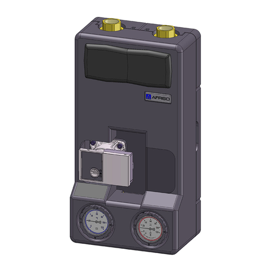
Produktbeschreibung Produktbeschreibung Das Produkt ist eine vormontierte, dichtheitsgeprüfte und wärmegedämmte Heizungspumpengruppe. Das integrierte temperaturgesteuerte Kondensati- onsschutzventil bildet die Verbindung zwischen der Feststoffheizung und dem Heizkreis oder dem Pufferspeicher. Das Produkt kann sowohl waagerecht als auch senkrecht montiert werden. Hierzu werden die Thermometer und der Pumpenkopf in die gewünschte Position gedreht. - Seite 8 Produktbeschreibung Übersicht A. Kondensationsschutzven- (nur bei 180-3 DN 25 RTA) B. Isolation C. Kugelhahn, absperrbar mit Thermometer rot und Schwerkraftbremse D. Kugelhahn, absperrbar mit Thermometer blau E. Umwälzpumpe (verschiedene Hersteller) F. Kugelhahn G. Haltewinkel H. 3-Wege-Mischer mit Stell- motor (nur bei 180-2 DN 25 RTA) 1.
- Seite 9 Produktbeschreibung Varianten Die variable Isolation ist für den Einsatz mit Vorlauf links oder Vorlauf rechts einsetzbar. Abbildung 1: Vorlauf rechts (Abbildung links) Abbildung 2: Vorlauf links (Abbildung rechts) 180-2 DN 25 RTA / 180-3 DN 25 RTA...
- Seite 10 Produktbeschreibung Abmessungen und Anschlüsse ca. 122 mm ca. 153 mm ca. 250 mm 180-2 DN 25 RTA / 180-3 DN 25 RTA...
- Seite 11 Produktbeschreibung ca. 125 mm Funktion Die PrimoTherm® 180-2 DN 25 RTA mit 3-Wege-Mischer und Mischer Antrieb wird bei Festbrennstoff-Kesseln eingesetzt, welche über eine Rege- lung zur Rücklauftemperaturanhebung verfügen. Die Einstellungen der Öff- nungstemperatur müssen an dieser Regelung erfolgen. Die PrimoTherm® 180-3 DN 25 RTA regelt die Rückflusstemperatur des Sys- temwassers zum Wärmeerzeuger automatisch auf den im Ventil eingestell- ten Wert.
- Seite 12 Produktbeschreibung 4.4.1 PrimoTherm® 180-2 DN 25 RTA Bei dieser Ausführung werden die einzelnen Betriebsphasen durch die Kesselregelung des Mischers gesteuert. - Rücklauf Speicher „A“ - Bypass „B“ Abbildung 3: Startbetrieb (Heizen des Kessels), Übergangsphase bei Erreichen der Öffnungstemperatur und laufender Betrieb 4.4.2 PrimoTherm®...
- Seite 13 Produktbeschreibung Wird die Öffnungstemperatur erreicht (beispielsweise 55 °C), wird der Kreis- lauf zum Verbraucher (Rücklauf Speicher A) anteilig geöffnet, der Bypass (B) wird entsprechend reduziert. Die Kesseltemperatur steigt unter Wärmeabgabe an den Verbraucher an, die Rücklauftemperatur wird jedoch in keinem Fall unter die eingestellte Tempe- ratur fallen.
- Seite 14 Produktbeschreibung Zulassungsdokumente, Bescheinigungen, Erklärungen Bei Ausführung mit Umwälzpumpe, siehe Anleitung des Pumpenherstellers. Technische Daten Parameter Wert 180-2 DN 25 RTA 180-3 DN 25 RTA Allgemeine Daten Abmessungen mit Isolation 250 x 475 x 153 mm (B X H X T) Gewicht Ca.
-
Seite 15: Montage
Montage Montage WARNUNG VERBRENNUNGEN DURCH HEISSE FLÜSSIGKEIT Wasser in Heizungsanlagen steht unter einem hohen Druck und kann Tempe- raturen bis über 100 °C erreichen. • Stellen Sie sicher, dass das Heizwasser abgekühlt ist, bevor Sie die Anlage öffnen und das Produkt montieren. Nichtbeachtung dieser Anweisung kann zu Tod, schweren Verletzungen oder Sachschäden führen. - Seite 16 Montage 5.1.1 Umwälzpumpe einbauen Verwenden Sie nur Umwälzpumpen mit einer konstanten Drehzahl. 1. Bauen Sie die Umwälzpumpe mit einer Baulänge von 180 mm ein (nur bei PrimoTherm® ohne Umwälzpumpe). - Anschlussgewinde G1½, Anzugsdrehmoment 80 Nm. 5.1.2 Vorlauf/Rücklauf tauschen Falls nicht anders angegeben, beziehen sich alle Angaben in dieser Betriebsanleitung auf die Einbauweise „Vorlauf Speicher rechts“.
- Seite 17 Montage A. Vorlauf Speicher B. Rücklauf Speicher C. Blauer Thermometer- Kugelhahn D. Roter Thermometer- Kugelhahn Abbildung 8: Vorlauf Speicher links 180-2 DN 25 RTA / 180-3 DN 25 RTA...
- Seite 18 Montage 1. Tauschen Sie den linken und rechten Strang. 2. Drehen Sie den Pum- penkopf. 3. Setzen Sie die obere Iso- lation auf. 5.1.3 Temperaturfühler montieren (optional) Je nach Typ des Temperatur- fühlers (B) kann es nötig sein die Klemmhülse (A) zu kür- zen.
-
Seite 19: Mechanische Belastung Und Verspannung
Montage Produkt montieren 5.2.1 Wandmontage HINWEIS MECHANISCHE BELASTUNG UND VERSPANNUNG • Stellen Sie bei der Montage des Produkts an der Wand sicher, dass das Pro- dukt keinen mechanischen Belastungen und Verspannungen ausgesetzt ist. • Stellen Sie beim Anschließen der Rohrleitungen des Heizkreises sicher, dass das Produkt keinen mechanischen Belastungen und Verspannungen ausgesetzt ist. - Seite 20 Montage 1. Entfernen Sie die obere Isolation. 2. Halten Sie das Produkt an die Wand und richten es mit einer Wasserwaage aus. 3. Zeichnen Sie sechs Markierun- gen an. 4. Verbinden Sie die gegenüberlie- genden Markierungen miteinan- der. 5. Bohren Sie an den mittleren Mar- kierungen jeweils ein Loch (Ø...
- Seite 21 Montage 8. Drehen sie, bei horizontaler Ein- baulage, das Thermometer um 90°. 9. Hängen Sie das Produkt mit der unteren Isolation ein und sichern Sie das Produkt mit Unterlegscheibe und Mutter. 10.Verbinden und verschrauben Sie die Rohrleitungen des Heizkreises mit den Anschlüssen der Armaturen spannungsfrei.
-
Seite 22: Elektrischer Schlag
Montage Elektrischer Anschluss GEFAHR ELEKTRISCHER SCHLAG • Stellen Sie sicher, dass durch die Art der elektrischen Installation der Schutz gegen elektrischen Schlag (Schutzklasse, Schutzisolierung) nicht vermin- dert wird. Nichtbeachtung dieser Anweisungen führt zu Tod oder schweren Verlet- zungen. GEFAHR ELEKTRISCHER SCHLAG DURCH SPANNUNGSFÜHRENDE TEILE •... - Seite 23 Inbetriebnahme Inbetriebnahme Produkt in Betrieb nehmen Stellen Sie sicher, dass die Thermometer-Kugelhähne in 0°-Stellung sind. 1. Führen Sie eine Druckprobe durch. 2. Prüfen Sie alle Verschraubungen auf Dichtheit. 3. Bringen Sie zum Befüllen der Anlage die Kugelhähne in 45°-Stellung. 4.
-
Seite 24: Betrieb
Betrieb Betrieb Ein einwandfreier Betrieb ist nur bei offenen Thermometer-Kugelhähnen und Kugelhähnen möglich (0°-Stellung, siehe Kapitel "Thermometer-Kugel- hahn"). Wartung Wartungsintervalle Zeitpunkt Tätigkeit 1 x monatlich Prüfen Sie die Heizungsanlage visuell auf Undichtigkeit. Bei Bedarf Tauschen Sie die Umwälzpumpe aus. Wartungstätigkeiten GEFAHR ELEKTRISCHER SCHLAG DURCH SPANNUNGSFÜHRENDE TEILE •... -
Seite 25: Störungsbeseitigung
Luft in der Anlage Entlüften Sie die Anlage sche Umwälzpumpe ist falsch Überprüfen Sie die Ein- eingestellt stellung der Umwälz- pumpe Sonstige Störungen Bitte wenden Sie sich an die AFRISO-Service Hotline 180-2 DN 25 RTA / 180-3 DN 25 RTA... -
Seite 26: Außerbetriebnahme Und Entsorgung
Vor einer Rücksendung Ihres Produkts müssen Sie sich mit uns in Verbin- dung setzen. Gewährleistung Informationen zur Gewährleistung finden Sie in unseren Allgemeinen Geschäftsbedingungen im Internet unter www.afriso.com oder in Ihrem Kauf- vertrag. 180-2 DN 25 RTA / 180-3 DN 25 RTA... -
Seite 27: Ersatzteile Und Zubehör
Ersatzteile und Zubehör Ersatzteile und Zubehör HINWEIS BESCHÄDIGUNG DURCH UNGEEIGNETE TEILE • Verwenden Sie nur Original Ersatz- und Zubehörteile des Herstellers. Nichtbeachtung dieser Anweisung kann zu Sachschäden führen. Produkt Artikelbezeichnung Art.-Nr. Abbildung PrimoTherm „180-2 DN 25 77541 RTA“ 3WM-SM OP G1 x G1, ohne Umwälz- pumpe PrimoTherm „180-2 DN 25... - Seite 28 Ersatzteile und Zubehör Artikelbezeichnung Art.-Nr. Abbildung PrimoTherm „180-3 DN 25 77578 RTA“ 55 OP G1 x G1, ohne Umwälz- pumpe PrimoTherm „180-3 DN 25 77570 RTA“ 60 WPOP G1 x G1, mit WILO Yonos PARA 25/6 RKC PrimoTherm „180-3 DN 25 77571 RTA“...
- Seite 29 Ersatzteile und Zubehör Ersatzteile und Zubehör Artikelbezeichnung Art.-Nr. Abbildung Isolation + Wandbefesti- 77540 gungsset + Zubehör Wandbefestigungsset 77588 Pumpenkugelhahn mit 77539 Schwerkraftbremse vor- montiert Rücklaufstrang 77538 (beinhaltet Pumpenkugel- hahn mit Schwerkraft- bremse vormontiert und Distanzrohr) 180-2 DN 25 RTA / 180-3 DN 25 RTA...
- Seite 30 Ersatzteile und Zubehör Artikelbezeichnung Art.-Nr. Abbildung Pumpenkugelhahn vor- 77537 montiert Pumpenkugelhahn 77536 x Flansch 3-Wege-Mischer mit 77589 T-Stück KV10 Kond.-Schutzv. 740 KVs 77534 3,5/60 °C mit T-Stück Kond.-Schutzv. 740 KVs 77533 3,5/45 °C mit T-Stück Kond.-Schutzv. 740 KVs 77532 3,5/55 °C mit T-Stück 180-2 DN 25 RTA / 180-3 DN 25 RTA...
- Seite 31 Ersatzteile und Zubehör Artikelbezeichnung Art.-Nr. Abbildung Thermometerset RTA 77530 VL blau/RL rot mit Schwer- kraftbremsen-Symbol Stellmotor ARM 343 6 Nm, 78208 230 V, 120 s Anschlussset (primärseitig) 77612 G1½ x G1 Anschlussset (sekundär- 77613 seitig) G1½ x G1 180-2 DN 25 RTA / 180-3 DN 25 RTA...