Wavetek Meterman LCR55 Bedienungsanleitung
Component tester

Verwandte Anleitungen für Wavetek Meterman LCR55

Inhaltszusammenfassung für Wavetek Meterman LCR55
- Seite 1 ¤ Operator’s Manual Model LCR55 Component Tester • Bedienungsanleitung • Manual de Instrucciones • Manuel d’Utilisation...
- Seite 2 F GARANTIE Le multimètre digitaux, Modèle LCR55 est garanti pour un (1) an à partir de la date d’achat contre les défauts de matériaux et de fabrication. Voir chapitre "Maintenance et Réparation" pour plus de détails.
-
Seite 3: Inhaltsverzeichnis
Safety Information ..........2 CONTENTS Instrument Familiarization........4 Measurement Procedures ........6 Specifications ........... 18 Maintenance and Repair ........26 Sicherheitsinformationen ........2 D • Inhalt Vorstellung des Gerätes ........4 Meßprozeduren ........... 6 Spezifikationen ..........20 Unterhalt und Reparatur ........26 Información de seguridad ........ -
Seite 4: Warnings And Precautions
WARNINGS AND PRECAUTIONS I This instrument is EN61010-1 certified for Installation Category II. (local level power distribution, appliances, portable equipment, etc, where only smaller transient overvoltages may occur). I Do not exceed the maximum overload limits per function (see specifications) nor the limits marked on the instrument itself. I Inspect instrument, test leads and accessories before every use. -
Seite 5: Overload Indication
jamais les limites de surcharge continue par fonction (voir spécifications) ou d’autres limites marquées sur l’appareil. I Inspectez appareil, câbles, connecteurs avant chaque mesure. N’utilisez pas des pièces endommagées I Ne touchez pas les pointes de touche ou le circuit pendant les mesures • Isolez-vous ! I Ne remplacez les fusibles que par des fusibles équivalents. -
Seite 6: Preparation For Use - Unpacking
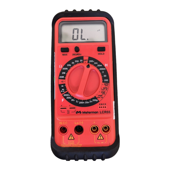
E • Preparación del instrumento para su uso - Desembalaje El embalaje debe contener: el LCR55, un juego de puntas de prueba (una negra y otra roja), un par de pinzas de cocodrilo, una pila de 9 V (instalada), un fusible de repuesto de 0.1A/250V (dentro de la carcasa), una tarjeta de garantía y este manual. - Seite 7 LCR55 3-1/2 digit LCD; decimal point, function and unit indicators 3-1/2 Digit LCD ; Dezimalpunkt, Funktions- und Einheitsanzeigen LCD de 3-1/2 dígitos, punto decimal, indicadores de función y unidades Zero adjustment for LCD 3-1/2 digits ; point décimal, indicateurs de fonctions et 20Ω...
-
Seite 8: Measuring Procedures
MEASURING PROCEDURES General Procedures: ❶ When connecting or disconnecting test leads to/from a circuit, always first turn off power to device or circuit being tested and discharge all capacitors. ❷ If the magnitude of a signal to be measured is not known, set selector switch to highest range first and reduce until satisfactory reading is obtained. - Seite 9 Cathode 200k 200m Cathode Anode M.W. (Icec A) 2000 (Icec A) 200p 200n E B C E LCR55 Hi(+) Lo(-) 200mA MAX FUSED Lx Cx FUSED MAX 350V DISCHARGE CAPACITOR BEFORE CONNECTING red/rot/roja/rouge D • Widerstandsmessung (siehe Fig. 1) ❶ Es darf keine Spannung am Widerstand anliegen. Kondensatoren entladen. Eine Spannung würde die Messung verfälschen.
- Seite 10 Note 2: The test procedure of microwave oven diodes is identical to regular diodes except forward voltage drop will be higher (3 or more volts) than standard silicon diodes. LEDs may also be tested with the LCR55 in the M.W. position. D • Dioden- und Transistortest Der Diodentest zeigt den Spannungsabfall über den Diodendurchgang ❶...
- Seite 11 Anode Cathode 200k 200m Cathode Anode M.W. (Icec A) 2000 (Icec A) 200p 200n E B C E LCR55 Hi(+) Lo(-) 200mA MAX FUSED Lx Cx FUSED MAX 350V DISCHARGE CAPACITOR BEFORE CONNECTING Fig. 2 red/rot/roja/rouge - 9 -...
-
Seite 12: Continuity Test
E • Comprobación de diodos y transistores (vea Fig. 2) En esta prueba se mide la caída de tensión en la unión del diodo. ❶ Conecte la punta de prueba roja a la entrada +Rx y la negra a la entrada -Rx. ❷ Ponga el selector de función en o en M.W. - Seite 13 Note 2: The capacitance range is protected by a 0.1A/250V fast blow fuse. If fuse blows, replace with same (see Battery and Fuse Replacement). Note 3: The LCR55 has a residual capacitance of approximately 6pF in the 200nF range. When using the 200nF range, note the residual capacitance and subtract this value from the measured value.
- Seite 14 Bereich “OL” angezeigt wird, dann ist der Kondensator zu groß um gemessen zu werden. Anmerkung 1: Die Anschlüsse kleinerer Kondensatoren können zum Messen auch gleich in die Cx/Lx Schlitze am LCR55 eingesteckt werden. Anmerkung 2: Die Kapazitätsbereiche sind mit einer 0.1A/250V flinken Sicherung abgesichert. Wenn die Sicherung durchbrennt, mit gleichwertiger ersetzen (siehe Batterie- und Sicherungswechsel).
- Seite 15 “Sustitución de la pila y el fusible”). Nota 3: El LCR55 tiene una capacidad residual de unos 6 pF en la escala de 200 nF. Si utiliza dicha escala de 200 nF, anote la capacidad residual y reste su valor del valor medido.
- Seite 16 LCR55 gemessen zu werden. Anmerkung 1: Die Anschlüsse kleinerer Spulen können zum Messen auch gleich in die Cx/Lx Schlitze am LCR55 eingesteckt werden. Anmerkung 2: Die Induktivitätsbereiche sind mit einer 0.1A/250V flinken Keramik- Sicherung abgesichert. Wenn die Sicherung durchbrennt, mit gleichwertiger ersetzen (siehe Batterie- und Sicherungswechsel).
- Seite 17 LCR55. Note 1: Les conducteurs de petites bobines peuvent être insérés directement dans les fentes Cx/Lx du LCR55. Note 2: Les calibres d’inductance sont protégés par un fusible céramique rapide de 0.1A/250V. Si le fusible saute, remplacez-le par un fusible identique. (voir...
-
Seite 18: Max Function
F • Mesure du Gain de Transistors Le transistor doit être enlevé du circuit. ❶ Placez le sélecteur sur la position PNP ou NPN, selon le type de transistor à tester. ❷ Insérez les conducteurs d’émetteur, de base et de collecteur dans les trous appropriés du socket de test. ❸ Lisez le gain tu transistor h beta, sur l’afficheur Note: Pour mesurer le courant collecteur-émetteur, placez le sélecteur sur la... -
Seite 19: Safety Test Leads
Taste erneut drücken um die Anzeige freizugeben. E • Retención de Lecturas (HOLD) Pulse la tecla HOLD para mantener congelada la lectura del visualizador. Dicha lectura se mantiene aunque se retiren las puntas de prueba del circuito. Para liberar el visualizador, pulse de nuevo HOLD. F •... -
Seite 20: General Specifications
SPECIFICATIONS General Specifications EMC: This product complies with requirements of the Display: 3 1/2 digit LCD, 1999 counts, following European Community 0.7” (17.8mm) high numerals, unit Directives: 89/336/EEC (Electromagnetic annunciators and function symbols Compatibility) and 73/23/EEC (Low Polarity Indication: Automatic, positive Voltage) as amended by 93/68/EEC (CE Marking). -
Seite 21: Optional Accessories
OL Protection: 350VDC or AC RMS Test Frequency: 200µH to 2H rgs: 1000Hz; 20 and 200H ranges: 100Hz Diode Test Temperature Coefficient, ≤0.5H: Test Current: 1mA (approx.) 0.2%/°C; >0.5H: 0.5%/°C Test Voltage: 3.0VDC typical OL Protection: 0.1A/250V fast blow Accuracy: ±(1.5%rdg +1dgt) fuse Display: Forward Junction Voltage OL Protection: 350VDC or AC RMS... -
Seite 22: Allgemeine Spezifikationen
SPEZIFIKATIONEN Allgemeine Spezifikationen (Elektromagnetische Kompatibilität) und 73/23/EEC (Niedrige Spannung) Anzeige: 3 -stelliges LCD, 1999 geändert durch 93/68/EEC (CE Punkte, 0.7” (17.8mm) hohe Ziffern, Marking). Einheits- und Funktionsanzeigen Polaritätsanzeige: Automatisch, positiv Elektrisches Rauschen und starke unterstellt, negativ angegeben magnetische Felder in der direkten Nullabgleich: Automatisch Umgebung des Meßgerätes können Überlastanzeige: “OL”... - Seite 23 Ansprechzeit: ung. 800ms Überlastschutz: 350VDC oder AC eff. Überlastschutz: 350VDC oder AC eff. +30Dgt)* 2 bis 200mH: ±(3.0%vMW +20Dgt)* Diodentest 2 bis 200H: ±(5.0%vMW +20Dgt)* Teststrom: 1mA (approx.) *Fur Induktore mit Q ≤ 7 Testspannung: 3.0VDC typisch Testspannung: 3.0VDC typisch Genauigkeit: ±(1.5%vMW +1Dgt) Testfrequenz: 200µH bis 2H Ber: Anzeige: Spannungsabfall...
-
Seite 24: Especificaciones Generales
ESPECIFICACIONES Especificaciones generales Directivas de la Comunidad Europea: 86/336/EEC (Compatibilidad Visualizador: LCD de 3-1/2 dígitos, 1999 Electromagnética) y 73/23/EEC (Baja cuentas, dígitos de 17.8 mm de altura, Tensión), con enmiendas según símbolos de función e indicación de 93/68/EEC (Marcado CE). unidades No obstante, la presencia de ruido Indicación de polaridad: Automática,... -
Seite 25: Accesorios Opcionales
200 µH a 2 H: 1000 Hz 20 y 200 H: 100 Hz Prueba de diodos Coeficiente de temperatura, ≤ 0.5 H: Corriente de medida: 1 mA aprox. 0.2%/ºC; >0.5 H: 0.5%/°C Tensión de medida: 3.0 VCC típ. Protección sobrecarga: Fusible de Precisión: ±(1.5% lect + 1 dgt) actuación rápida, 0.1A/250V Indicación: Tensión directa de la unión... -
Seite 26: Spécifications
SPECIFICATIONS Spécifications Générales 73/23/EEC (Basse Tension), modifiée par 93/68/EEC (CE Marking). Affichage: LCD 3 digits, 1999 Cependant, du bruit électrique ou des points, chiffres de 17.8mm), champs électromagnétiques intenses indicateurs d’unités et de fonctions. dans la proximité de l’instrument Indication de polarité: Automatique, peuvent influencer le circuit de mesure. -
Seite 27: Accessoires En Option
200, 2000µF H30Y Holster de protection Précision*, calibres: VC30 Sacoche en vynil 200pF à 200nF: ±(1.0% lect +1dgt) VC231 Sacoche en vynil (LCR55 2µF à 200µF: ±(2.0% lect +1dgt) et holster) 2000µF: DL243C Cordons de mesure ≤ 1000µF ±(3.0% lect +3dgt) standards ≥... -
Seite 28: Maintenance And Repair
TROUBLESHOOTING / MAINTENANCE If there appears to be a malfunction during the operation of the meter, the following steps should be performed in order to isolate the cause of the problem: ❶ Check the battery. ❷ Review the operating instructions for possible mistakes in operating procedure. -
Seite 29: Battery / Fuse Replacement
BATTERY / FUSE REPLACEMENT Warning: To prevent electrical shock hazard, turn off the multimeter and any device or circuit under test and disconnect the test leads before removing the rear cover. ❶ Remove the screws and lift off the rear case ❷ Fuse Replacement: Remove the blown fuse (5 x 20mm) from the fuse holder. - Seite 30 F • Remplacement Pile et Batterie Avertissement: Avant d’ouvrir l’appareil, coupez l’alimentation et retirez les cordons de test. ❶ Enlevez les vis et soulevez le boîtier arrière. ❷ Remplacement du fusible: Enlevez le fusible brulé et remplacez-le par un fusible rapide équivalent 0.1A/250V (5 x 20mm) (un fusible de réserve est contenu dans le compartiment de la pile.
- Seite 31 E • Calibración Este procedimiento debe hacerse a una temperatura ambiente de 25°C ±2°C, con humedad relativa <70%. Deje transcurrir al menos 30 minutos a dicha temperatura para que se estabilice el medidor. Advertencia: Este procedimiento debe hacerse exclusivamente por personal preparado para calibrar instrumentos de medida.
- Seite 32 Service charges should be remitted in the form of a check, a money order, credit card with expiration date, or a purchase order made payable to Wavetek Meterman or to the specific service center. For minimum turn-around time on out-of-warranty repairs please phone in advance for service charge rates.
- Seite 33 Si la reparación es en garantía, puede llevar el multímetro defectuoso a cualquier Distribuidor Autorizado o Centro de Servicio de Wavetek Meterman, donde le cambiarán en mano el producto por otro igual o similar. Para reparaciones fuera de garantía deberá enviar el multímetro a un Centro de Servicio de Wavetek Meterman.
- Seite 34 Meterman pour un échange direct. Pour une réparation hors garantie, envoyez votre multimètre à un Centre de Services agrée par Wavetek Meterman . Téléphonez à Wavetek Meterman ou demandez à votre revendeur pour l’adresse la plus proche. Pour les réparations hors garantie, demandez dabord les tarifs. Joignez les informations et documents suivants: nom de sociètè, nom du client, adresse,...
- Seite 36 Fax: (425) 446-6390 Manual Part Number 1566247 Canadian Service Center Information contained in this manual Wavetek Meterman is proprietary to Wavetek Meterman and is provided solely for instrument 400 Britannia Rd. E.Unit #1 operation and maintenance. The Mississauga, ON L4Z 1X9...