
Verwandte Anleitungen für Honeywell BA 299 I


Inhaltszusammenfassung für Honeywell BA 299 I
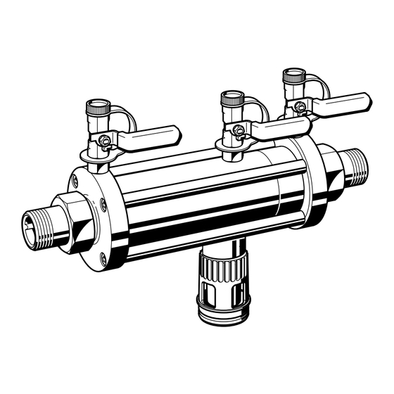
- Seite 1 BA 299 I Einbau-Anleitung . Installation Instruction . Instructions de montage Systemtrenner Typ BA BA type back flow preventers Disconnecteurs type BA...
-
Seite 2: Funktionsweise
Je höher die Klassifizierung, umso größer ist das Gefahrenpotential. Für jede Kategorie schreibt auch wenn keine Wasser- Zone 1 und Zone 2 auf beide Rückflußverhinderer DIN pr EN 1717 bestimmte Sicherungsarmaturen vor. BA 299 I Systemtrenner sind uneinge- entnahme erfolgt. 0,14 bar abgesunken ist. undicht sind, öffnet das schränkt zugelassen für Anwendungen bis einschließlich Kategorie 4. -
Seite 3: Installation
3. Installation 3.1 Hinweise für eine sichere Installation Der Raum, in dem der Systemtrenner installiert ist, muß Abb.1 Der Systemtrenner BA muß waagerecht installiert werden. Vor jederzeit gut zugänglich und frostfrei sein. Auf eine gute und nach dem Systemtrenner sind Absperrventile einzubauen. Belüftung sollte geachtet werden. - Seite 4 4. Inbetriebnahme 5. Entlastungsventil am Differenzdruckmeßgerät wieder schließen Der Differenzdruck muß nun konstant bleiben, sonst ist Die Inbetriebnahme des Systemtrenners in der folgenden der Eingangs-Rückflußverhinderer undicht. Mögliche Reihenfolge vornehmen: Ursachen sind Verschmutzung oder mechanischer Defekt. 1. Absperrventile 1 und 2 langsam öffnen Kapitel 6.1 Austausch der kompletten Wartungseinheit.
-
Seite 5: Wartung
6. Wartung 5. Kugelhahn 5 an der Wartungseinheit ausschrauben. 6. Komplette Wartungseinheit 9 entnehmen. Zu Wartungszwecken kann die komplette Wartungseinheit 7. Neue Wartungseinheit einsetzen. bestehend aus Gehäuse mit ein- und ausgangsseitigem 8. Kugelhahn 5 an der Wartungseinheit einschrauben. Rückflußverhinderer und Ablaßventil ausgebaut werden. Alle Arbeiten können ohne Ausbau des Geräts aus der Rohrleitung ) durchgeführt werden. -
Seite 6: Wichtige Hinweise Zu Ihrer Sicherheit
10 bar die die Sicherheit beeinträchtigen können, umgehend beseiti- Mindesteingangsdruck: 1,0 bar gen lassen. Kugelhahnanschluß: " Systemtrenner des Typs BA 299 I sind ausschließlich für die in Anschlußgröße Gewicht Gesamtlänge Nenndurchfluß in DVGW dieser Einbau-Anleitung genannten Einsatzgebiete bestimmt. /h bei ∆p=1bar ca. -
Seite 7: Gerät Im Schnitt
11. Gerät im Schnitt 12. Materialliste Ausführung Wartungseinheit bestehend aus Gehäuse aus nichtrostendem Stahl Ablaßventil aus nichtrostendem Stahl Rückflußverhinderer aus POM Faltenbalg aus nichtrostendem Stahl Dichtscheiben aus EPDM bzw. aus NBR Ventilsitz aus nichtrostendem Stahl a) Ablaßventil Sonstige Innenteile aus nichtrostendem Stahl b) Eingangsseitiger Rückflußverhinderer Flansche aus nichtrostendem Stahl c) Ausgangsseitiger Rückflußverhinderer... -
Seite 8: Method Of Operation
The higher the classification, the greater the risk potential. DIN pr EN 1717 defines acceptable Flow position Shutoff position Threefold protection safety protection devices for every risk category. BA 299 I backflow preventers are permitted as long as the differential The discharge valve opens Two non-return check without restriction for all risk categories up to and including risk category 4. - Seite 9 3. Installation 3.1 Guidelines for a safe installation Type BA backflow preventers must be installed horizontally. The location where the backflow preventer is installed must Fig. 1 Shutoff valves should be fitted on both sides. In addition, a be accessible at all times and be free from frost. Good strainer (see Section 11.
-
Seite 10: Putting Into Service
4. Putting Into Service The differential pressure must now remain constant, otherwise the inlet non-return check valve is not sealing. The backflow preventer is put into service in the following Possible causes for this are dirt or a mechanical defect. sequence: Section 6.1 - Replacement of the service replacement 1. -
Seite 11: Maintenance
6. Maintenance 5. Unscrew ball valve 5 from the service replacement cartridge. For maintenance purposes the service replacement cartridge, 6. Remove complete service replacement cartridge 9. comprising the inlet and outlet non-return check valves and the 7. Insert new service replacement cartridge. discharge valve, can be removed. -
Seite 12: Important Safety Guidelines
Minimum inlet pressure: 1.0 bar Ball valve connection: " Type BA 299 I backflow preventers are exclusively for use in applications detailed in these installation instructions. Any other Connection size Weight Total length Nominal flow rate DVGW use will not comply with requirements. - Seite 13 11. Sectional View 12. Materials Construction Body interchangeable comprising Stainless steel housing Stainless steel discharge valve POM non-return check valve Stainless steel bellows EPDM and NBR seal discs Stainless steel valve seat a) Discharge valve Stainless steel inner components b) Inlet non-return check valve Stainless steel flanges c) Outlet non-return check valve Stainless steel union connectors...
- Seite 14 1 et la zone 2 est s’ouvre à l’atmosphère au chaque catégorie des garnitures de protection particulières. Les disconnecteurs BA 299 I sont divisent le disconnecteur en de > 0,14 bar, la soupape plus tard au moment où la trois sections.
- Seite 15 3.1 Indications pour une installation sûre 3. Installation La pièce dans laquelle le disconnecteur est installé doit Fig.1 Le disconnecteur BA doit être installé horizontalement. Des soupapes d’arrêt doivent être installées avant et après toujours être accessible et résistante au gel. le disconnecteur.
-
Seite 16: Mise En Service
4. Mise en service 5. Refermer la soupape de décharge de l’appareil de mesurage de pression differentielle. La mise en service du disconnecteur est à effectuer La pression différentielle doit rester constante, sinon le dans l’ordre suivant: clapet de non-retour d’entrée a des fuites. Des causes 1. -
Seite 17: Entretien
5. Dévisser le robinet à boisseau sphérique 5 de l’unité 6. Entretien d’entretien. L’unité d’entretien complète, comprenant un corps avec 6. Enlever l’unité d’entretien complète. clapet de non-retour d’entrée et de sortie et une soupape 7. Placer la nouvelle unité d’entretien. de décharge, est démontable pour des mesures d’entretien. -
Seite 18: Conseils De Sécurité Importants
Raccordement pour robinets risquant de porter atteinte à la sécurité. " à boisseau sphérique: Les disconnecteurs du type BA 299 I sont destinés Diamètre de Poids env. Kg Longueur totale débit nominal DVGW numéro de exclusivement aux domaines d’utilisation mentionnés dans la... - Seite 19 11. Appareil en coupe 12. Liste du matériel Constrution Unité d’entretien composée de Corps en acier inoxydable Soupape de décharge en acier inoxydable Clapet de non-retour en POM Soufflet en acier inoxydable Bagues d’étanchéité en EPDM ou en NBR Siège de soupape en acier inoxydable Autres pièces intérieures en acier inoxydable a) Soupape de décharge Brides en acier inoxydable...
- Seite 21 Honeywell AG Hardhofweg . D-74821 Mosbach (Germany)