Rennsteig PEW 8.75 Betriebsanleitung
Vierdorncrimpzange mit digitalanzeige
Quicklinks
Setting of crimping values
•
Please refer to the enclosed setting charts for crimping depth adjustment and locator selection
•
Crimp values (crimp depth of indenters) are set by turning the adjustment screw as long as the display
shows the requested value
•
Loosen the Clamping Screw and take care that the gauge parameter has been set starting always with a
higher value, e.g. setting from 1,8 mm to 1,5 mm
•
Turning the adjustment screw clockwise reduces the crimp values whereas turning counter-clockwise
increases the value
•
Lock the set value by means of the clamping screw
•
Select locator for the contact to be crimped by lateral lifting and turning it into the position defined in the
attached chart
Crimping
•
Put the prepared cable into the contact to be crimped and insert
the contact as far as possible into the crimp recess of the tool; the
locator provides for the exact positioning of the contact
•
Close the tool to its fullest extent until it opens automatically
•
Remove the crimped contact
CAUTION! D O N O T C R I M P O N T O T H E G A U G E
W H E N I N S E R T E D O R A N Y O T H E R I T E M S
T H A T A R E N O T M E A N T F O R T H E I N T E N D E D
A P P L I C A T I O N ! D O N O T C R I M P O N S O L I D
M A T E R I A L E X C E E D I N G 3 5 H R C ( E . G . S T E E L ) !
Changing of battery
Service life of the battery for the digital display is approx. 1 year,
depending on how often it is used. To change the battery, pull out the
battery holder and remove the old battery. After a battery change the
tool needs to be reset.
Dispose of batteries only in accordance with local environmental
regulations!
Reset
CAUTION!
A D J U S T M E N T S H O U L D B E O N L Y B E C A R R I E D O U T B Y
P R O P E R L Y T R A I N E D A N D A U T H O R I Z E D P E R S O N N E L .
A D J U S T M E N T S M A Y R E S U L T I N I N C O R R E C T C R I M P I N G D I M E N S I O N S .
•
Indenters are to be set by the adjusting screw by inserting a gauge positioned inside the indenters Take
care that the gauge parameter has been set starting always with a higher value, e.g. setting from 2,4
mm to 2,0 mm. Take out the gauge when the setting is complete.
•
Keep the „ON" button pressed while actuating „MODE" by means of the gauge for at least 4 seconds
•
Then first release „MODE" and afterwards „ON"
•
The digital display automatically changes to 2,0 mm
•
The tool adjustment is then complete and the crimp depth can be set
Warranty
These roducts are subject to thorough quality control before leaving the factory. The enclosed general terms
and conditions of warranty apply.
Maintenance
Before using the crimping tool, make sure it is in a clean and proper operating state. Always remove crimping
residue. Protect the joints from soiling and apply light machine oil to them regularly. Check the bolts regularly
to ensure that the lock washers and headless screw, securing the adjustment dial, are intact and tight. All
other maintenance should be performed by the manufacturer.
I M P R O P E R R E P A I R V O I D S T H E W A R R A N T Y !
RENNSTEIG WERKZEUGE GmbH
An der Koppel 1 , 98547 Viernau, Germany
Phone 036847/441-0, Fax 036847/44114
Internet: http://www. rennsteig.com, e-mail: info@rennsteig.com
Betriebsanleitung
Vierdorncrimpzange mit Digitalanzeige
Art.-Nr. 618 075-3 6 (PEW 8.75-3) AWG 26 - 10
Allgemeines
Die Vierdorncrimpzange mit Digitalanzeige ist eine Handcrimpzange, gefertigt nach dem neuesten Stand der
Technik und den anerkannten sicherheits-technischen Regeln. Die Zange darf nur in technisch-einwandfreiem
Zustand benutzt werden. Die Vierdorncrimpzange wird zum Vercrimpen von gedrehten Verbindern für
Leiterquerschnitte von 0,08 – 6,0 mm² eingesetzt und ist nur für den in der Bedienungsanleitung
beschriebenen Zweck zu verwenden.
E I N E E I GE N M Ä C H T I GE V E R Ä N D E R U N G O D E R E I N E N I C H T B E S T I M M U N G S -
G E M Ä S S E V E R W E N D U N G D E R H A N D C R I MP Z A N G E SC H L I E S S T E I NE H A F -
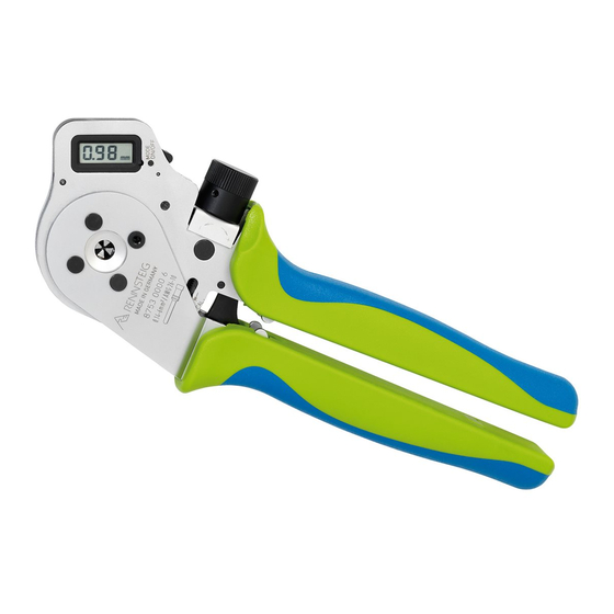
Battery holder for
T U N G D E S H E R S T E L L E R S F Ü R D A R A U S R E S U L T I E R E ND E S C H Ä DE N A U S .
type CR 2025
Verdeckter
Taster "MODE"
Digitalanzeige
Lateral
lifting and
turn
Crimpstelle
Clamping screw
Klemmschraube
zur Crimpmaß-
arretierung
für Zustell-
genauigkeiten
von 0,01 mm
I N C O R R E C T
Funktionsweise
Einschalten
•
Betätigung des Tasters ON oder Drehen des Stellrades in beliebiger Richtung
•
Standardanzeige erscheint in mm
Mode - Funktionen festlegen
Die Zange verfügt über eine Vielzahl von Anzeigefunktionen,
die über den Taster „MODE" ausgewählt werden können. Dies
ermöglicht dem Anwender die Einstellung wahlweise in mm, in
inch oder die Selectorpositionen von 1 - 8 entsprechend
MIL 22520 vorzunehmen.
Mit dem der Zange beiliegenden Lehrdorn den verdeckt
liegenden
gewünschte Anzeige in unten angegebener
auswählen.
Standard mm
display
Stellrad
Hinweis: Nach 1 min ohne Veränderung der Anzeige oder
Betätigung eines Tasters, schaltet sich die Digitalanzeige
automatisch ab (Energiesparfunktion).
Taster
„MODE"
kurzzeitig
betätigen
und
Reihenfolge
Inch
MIL selector
display
"ON" Taster
Endanschlag
12 tlg. Locator
Taster "Mode"
die
positions

Verwandte Anleitungen für Rennsteig PEW 8.75


Inhaltszusammenfassung für Rennsteig PEW 8.75
- Seite 1 Crimp values (crimp depth of indenters) are set by turning the adjustment screw as long as the display shows the requested value Art.-Nr. 618 075-3 6 (PEW 8.75-3) AWG 26 - 10 • Loosen the Clamping Screw and take care that the gauge parameter has been set starting always with a higher value, e.g.
- Seite 2 • Crimpdorn- und Locatoreinstellung für den zu vercrimpenden Batteriefach für Typ Verbinder aus beiliegender Matrix entnehmen. CR 2025 Art.-Nr. 618 075-3 6 (PEW 8.75-3) AWG 26 - 10 • Lösen der Feststellschraube (Anlieferzustand) • Die Crimpmaßeinstellung (Crimptiefe der Crimpdorne) READ THESE INSTRUCTIONS COMPLETELY BEFORE USING THIS TOOL durch Drehen der Stellschraube solange verändern, bis die...
- Seite 3 CE-Prüfung nach EMV EN 55014-1:2006,EN 55014-2:1997+A1:2001, Kat.III Prüfung durchgeführt durch: CE-LAB GmbH [DAT-P-209/05-00] Am Hammergrund 1 D-98693 Ilmenau FCC-Prüfung FCC 47 CFR Part 15 Subpart B Class B Prüfung durchgeführt durch: Herberg Service Plus GmbH [Reg. No. 96997] European Compliance Laboratory (ECL) Nordostpark 51 D-90411 Nürnberg...
- Seite 4 Einstellmaße für PEW 8.75 - Locator 01 Stand: Dezember 2006 Position SteckØ Leiterquerschnitt [mm²] [mm] 0,14 0,25 0,35 0,75 1,26 1,33 1,45 1,35 1,45 1,58 1,75 1,95 1,55 2,35 1,55 1,43 1,58 1,75 1,95 1,23 1,28 1,33 1,38 1,65 Einstellmaße für PEW 8.76 - Locator 01 Position SteckØ...