Herunterladen Diese Seite drucken

Westermo TD-29 DC Installationsanleitung

Multidrop 2-draht fsk-modem

Werbung

Verfügbare Sprachen

Verfügbare Sprachen

INSTALLATIONSANVISNING
INSTALLATION MANUAL
INSTALLATIONS ANLEITUNG
MANUEL D'INSTALLATION
6611-2001
Galvanic
Transient
Balanced
CE
Isolation
Protection
Transmission
Approved
Multidropp 2-tråd
Multidrop 2-wire
Multidrop 2-Draht
Multipoints 2-fils
www.westermo.com

Werbung

loading

Inhaltszusammenfassung für Westermo TD-29 DC

  • Seite 1 INSTALLATIONSANVISNING INSTALLATION MANUAL INSTALLATIONS ANLEITUNG MANUEL D’INSTALLATION 6611-2001 Galvanic Transient Balanced Isolation Protection Transmission Approved Multidropp 2-tråd Multidrop 2-wire Multidrop 2-Draht Multipoints 2-fils www.westermo.com...
  • Seite 2: Inhaltsverzeichnis

    Innehållsförteckning 1. Säkerhet ..................................2. Godkännanden ............................... 2.1 Tillverkningsdeklaration (Declaration of conformity) ............. 3. Introduktion ................................4. Specifikationer 6–7 ..............................4.1 Anslutningar ................................4.2 Isolation mellan gränssnitten ........................4.3 Temperaturområde ............................4.4 Mekanik ..................................4.5 Räckvidd och signaldämpning ........................4.6 Vändtider ..................................
  • Seite 3: Säkerhet

    1. Säkerhet Allmänt: Innan enheten används, läs denna manual fullständigt och jämför med uppgifter på enheten, samt säkerställ att du har förstått all information. Kontrollera att använ- dandet av enheten i din installation inte kommer att överskrida specificerade säkerhetsprestanda för enheten. Före installations-, underhålls- eller modifieringsarbete: Potentialutjämna dig till en jordnings punkt (tex.
  • Seite 4: Tillverkningsdeklaration (Declaration Of Conformity)

    2.1 Tillverkningsdeklaration (Declaration of conformity) SE.4 6611-2001...
  • Seite 5: Introduktion

    3. Introduktion TD-29 är konstruerad för kommunikation på 2-tråds partvinnad kopparkabel. Multidropp och punkt till punkt förbindelser med halvduplex är möjliga.TD-29 klarar halv duplex med 19.2 kbit/s som maximal överföringshastighet. TD-29 kan ställas in för att passa olika driftsförhållanden med hjälp av omkopplare. Såväl antal databitar som sändar- och mottagarnivåer samt olika kommunikationsgränssitt kan väljas.
  • Seite 6: Specifikationer

    4. Specifikationer 4.1 Anslutningar Matning TD-29 AC TD-29 DC TD-29 36–55 VDC Märkspänning 115 V/230 VAC 24 VDC 48 VDC Arbetsspänning 104–132/207–264 VAC 12–36 VDC 36–55 VDC Märkström 24 mA/12mA 200 mA 50 mA Märkfrekvens 48–62 Hz – – Anslutning...
  • Seite 7: Temperaturområde

    4.3 Temperaturområde Temperatur, drift 5–50°C Temperatur, lagring och transport –40 till +85°C Relativ fuktighet, drift 0 till 95% (icke kondenserande) Relativ fuktighet, 0 till 95% lagring och transport (kondensation utanför förpackning tillåten) 4.4 Mekanik Dimension (B x H x D) 55 x 100 x 128 mm Vikt 0,5 kg...
  • Seite 8: Underhåll

    5. Underhåll Inget krav på underhåll, så länge enheten används på avsett sätt inom specificerade förutsättningar. 6. Installation 6.1 Montering/Demontering Före montering eller demontering av enheten: Potentialutjämna dig till en jordnings punkt (tex. genom att använda handledsband), så att skada av intern elektronik på grund av elektrostatiska urladdningar (ESD) förhindras.
  • Seite 9: Anslutningar

    6.2 Anslutningar RS-232 5-polig skruvplint RS-422/RS-485 4-polig skruvplint 9-polig D-sub RS-232 Lysdioder Linjeanslutning Matningsanslutning 6.3 Lysdiodsindikeringar LED till Matningsspänning korrekt LED från Ingen matningsspänning LED till Mottagen linjedata LED från Ingen mottagen data LED till Sänd linjedata LED från Ingen sänddata LED till RTS från inkopplad utrustning LED från...
  • Seite 10: Gränssnitt 1 (Rs-232)

    6.4 Gränssnitt 1 (RS-232) 9-polig D-sub 9-polig Ansl. nr. Skruvplint Riktning Beskrivning – – – RD/Received Data TD/Transmitted Data – – – – SG/Signal Ground – DSR/Data Set Ready RTS/Request to Send CTS/Clear to Send – – – 6.5 Gränssnitt RS-422/485 9-polig ITU-T V.11 Skruvplint...
  • Seite 11: Inställning

    6.9 Inställning S2:1–4 S1:1–8 6.9.1 Switchinställningar DIP-switchar är tillgängliga under locket på toppen av modemet. DIP-switcharna används för att konfigurera enheten. Varning! Potentialutjämna dig till en jordnings punkt (tex. genom att använda handledsband), så att skada av intern elektronik på grund av elektrostatiska urladdningar (ESD) förhindras, innan locket på...
  • Seite 12 Switchblock 1 – S1 Val av antal databitar Val av Bärvågsaktivering 10 bitar 1 2 3 4 5 6 7 8 Data 1 2 3 4 5 6 7 8 11 bitar 1 2 3 4 5 6 7 8 1 2 3 4 5 6 7 8 Val av överföringshastighet Val av uteffekt*...
  • Seite 13: Funktionell Beskrivning

    7. Funktionell beskrivning 7.1 Blockdiagram D-Sub Screw terminal RD TD SG RTS TD RD SG B A B' A' S2:4 S2:3 RTS LED Amplifier S1:6 S2:2 CTS LED Line S2:1 TD LED switch S1:4 Line Demodulator S1:7 Isolated Power Supply Power Supply –5V 7.2 RS-422/485 anslutning...
  • Seite 14: Linjeanslutning

    7.3 Linjeanslutning 2-polig frånskiljbar skruvplint LINE CONNECTION POWER – LINE CONNECTION LINE CONNECTION LINE CONNECTION POWER POWER POWER – – – Multidropp halv duplex med TD-29 Terminering görs med DIP-switchar SE.14 6611-2001...
  • Seite 15 ANTECKNINGAR ................................................................................................................................................................................................................................................................................................................................................................................................................................................................................................................................................................................................................................................................6611-2001 SE.15...
  • Seite 16 Contents 1. Safety ....................................2. Approvals ................................... 2.1 Declaration of conformity .......................... 3. Introduction ................................4. Specifications 20–21 ............................. 4.1 Connections ................................4.2 Isolation between interfaces ........................4.3 Environmental ..............................4.4 Mechanical ................................4.5 Maximum range and signal loss ....................... 4.6 Turning time .................................
  • Seite 17: Safety

    1. Safety General: Before using this unit, read this manual completely and gather all information on the unit. Make sure that you understand it fully. Check that your application does not exceed the safe operating specifications for this unit. Before installation, maintenance or modification work: Prevent damage to internal electronics from electrostatic discharges (ESD) by discharging your body to a grounding point (e.g.
  • Seite 18: Declaration Of Conformity

    2.1 Declaration of Conformity GB.18 6611-2001...
  • Seite 19: Introduction

    3. Introduction The TD-29 is designed for communication on 2-wire copper cable (twisted pair). Multidrop or point to point is possible.The TD-29 will support half duplex at baud rates up to 19.2 kbit/s. The TD-29 is easy to configure for different operating conditions with DIP-switches. Character formats, baud rate, transmission level, DCD detection level and communica- tion interface are selectable.
  • Seite 20: Specifications

    4. Specifications 4.1 Connections Power TD-29 AC TD-29 DC TD-29 36–55 VDC Rated voltage 115 V/230 VAC 24 VDC 48 VDC Operating voltage 104–132/207–264 VAC 12–36 VDC 36–55 VDC Rated current 24 mA/12mA 200 mA 50 mA Rated frequency 48–62 Hz –...
  • Seite 21: Environmental

    4.3 Environmental Temperature, operating 5–50°C Temperature, storage and transportation –40 to +85°C Relative humidity, operating 0 to 95% (non-condensing) Relative humidity, 0 to 95% storage and transportation (condensation allowed outside packaging) 4.4 Mechanical Dimension (W x H x D) 55 x 100 x 128 mm Weight 0.5 kg Mounting...
  • Seite 22: Maintenance

    5. Maintenance No maintenance is required, as long as the unit is used as intended within the specified conditions. 6. Installation 6.1 Mounting / Removal Before mounting or removing the unit: Prevent damage to internal electronics from electrostatic discharges (ESD) by discharging your body to a grounding point (e.g.
  • Seite 23: Connections

    6.2 Connections RS-232 5-pos screw terminal RS-422/RS-485 4-pos screw terminal 9-pos D-sub RS-232 LED indicators Line connection Power supply 6.3 LED Status Indicators LED on Power on LED off Power off LED on Receive Line Data active LED off Receive Line Data inactive LED on Transmit Line Data active LED off...
  • Seite 24: Interface 1 (Rs-232)

    6.4 Interface 1 (RS-232) 9-pos. D-sub 9-pos. Pin. no. Screw terminal Direction Description – – – RD/Received Data TD/Transmitted Data – – – – SG/Signal Ground – DSR/Data Set Ready RTS/Request to Send CTS/Clear to Send – – – 6.5 Interface RS-422/485 9-pos.
  • Seite 25: Configuration

    6.9 Configuration S2:1–4 S1:1–8 6.9.1 DIP switch settings DIP-switches are accessable under the lid on top of the unit. DIP-switches are used to configure the modem. Warning! Prevent damage to internal electronics from electrostatic discharges (ESD) by discharging your body to a grounding point (e.g. use of wrist strap), before the lid on top of the modem is removed.
  • Seite 26 Switch block 1 – S1 Character format Carrier active using RTS or incoming data 10 bit/s 1 2 3 4 5 6 7 8 Data 1 2 3 4 5 6 7 8 11 bit/s 1 2 3 4 5 6 7 8 1 2 3 4 5 6 7 8 Selection of Baud rate 2 400 bit/s...
  • Seite 27: Functional Description

    7. Functional description 7.1 Block diagram D-Sub Screw terminal RD TD SG RTS TD RD SG B A B' A' S2:4 S2:3 RTS LED Amplifier S1:6 S2:2 CTS LED Line S2:1 TD LED switch S1:4 Line Demodulator S1:7 Isolated Power Supply Power Supply –5V 7.2 RS-422/485 connection...
  • Seite 28: Line Connection

    7.3 Line connection 2-position detachable screw terminal LINE CONNECTION POWER – LINE CONNECTION LINE CONNECTION LINE CONNECTION POWER POWER POWER – – – Multidrop half duplex with TD-29 Termination to be set with DIP-switches GB.28 6611-2001...
  • Seite 29 OWN COMMENTS ................................................................................................................................................................................................................................................................................................................................................................................................................................................................................................................................................................................................................................................................6611-2001 GB.29...
  • Seite 30 Inhalt 1. Sicherheit .................................. 2. Zulassungen ................................2.1 Konformitätserklärung ..........................3. Modem Beschreibung ..........................4. Technische Daten 34–35 ..........................4.1 Anschlüsse ................................4.2 Isolation zwischen Schnittstelle ......................4.3 Umgebungsbedingungen ..........................4.4 Mechanisches ................................ 4.5 Maximale Übertragungsweite und Signaldämpfungen ............4.6 Umschaltzeit .................................
  • Seite 31: Sicherheit

    1. Sicherheit Allgemeines: Vor dem Einsatz des Gerätes ist die Bedienungsanleitung vollständig zu lesen. Überprüfen Sie, dass der Einsatz dieser Geräte keine Vorschriften verletzt, und den Spezifikationen des Geräts entspricht. Vor der Installation,Wartung oder Modifikation: Vermeiden Sie Schaden an der Elektronik durch elektrostatische Aufladung (ESD) indem Sie sich vorher an einem Erdpunkt entladen (z.B.
  • Seite 32: Konformitätserklärung

    2.1 Konformitätserklärung DE.32 6611-2001...
  • Seite 33: Modem Beschreibung

    3. Modem Beschreibung Das TD-29 wurde für den Einsatz auf 2-Draht Kupferleitungen entwickelt (Twisted Pair). Multidrop oder Punkt zu Punkt Verbindungen sind möglich. Das TD-29 unterstützt halbduplex Übertragungen bis zu 19.2 Kbit/s. Das TD-29 kann mittels DIP-Schaltern einfach auf die Umgebungsbedingungen eingestellt werden.
  • Seite 34: Technische Daten

    4. Technische Daten 4.1 Anschlüsse Spannungsanschluss TD-29 AC TD-29 DC TD-29 36–55 VDC Eingangsspannung 115 V/230 VAC 24 VDC 48 VDC Betriebsspannung 104–132/207–264 VAC 12–36 VDC 36–55 VDC Stromaufnahme 24 mA/12mA 200 mA 50 mA Frequenz 48–62 Hz – –...
  • Seite 35: Isolation Zwischen Den Schnittstellen

    4.2 Isolation zwischen den Schnittstellen Netz zu allem AC: 3 kV RMS @ 50 Hz und 60s Dauer DC: 1 kV RMS @ 50 Hz und 60s Dauer FSK-Leitung Schnittstelle zu allem 1.5 kV RMS @ 50 Hz und 60s Dauer 4.3 Ungebungsparameter Betriebstemperatur 5–50°C...
  • Seite 36: Wartung

    5. Wartung Es sind keine Wartungsarbeiten erforderlich, solange das Gerät innerhalb der Spezifikation betrieben wird. 6. Installation 6.1 Montage/Demontage Vor der Montage oder Demontage des Geräts: Vermeiden Sie Schaden an der Elektronik durch elektrostatische Aufladung (ESD) indem Sie sich vorher an einem Erdpunkt ent- laden (z.B.
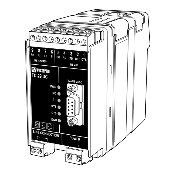
  • Seite 37: Anschlüsse

    6.2 Anschlüsse RS-232 5-polige Schraubklemme RS-422/RS-485 4-polige Schraubklemme 9-polige Sub-D für RS-232 Anschluß LED’s Leitungsanschluß Spannungsanschluß 6.3 LED Status Anzeigen LED on Power on LED off Power off LED on Receive Line Data active LED off Receive Line Data inactive LED on Transmit Line Data active LED off...
  • Seite 38: Schnittstelle 1 (Rs-232)

    6.4 Schnittstelle 1 (RS-232) 9-pol. Sub-D 9-pol Pin-Nr. Schraubklemme Richtung Beschreibung – – – RD/Received Data TD/Transmitted Data – – – – SG/Signal Ground – DSR/Data Set Ready RTS/Request to Send CTS/Clear to Send – – – 6.5 Schnittstelle 2 (RS-422/485) 9-pol ITU-T V.11 Schraubklemme...
  • Seite 39: Konfiguration

    6.9 Konfiguration S1:1–8 S2:1–4 6.9.1 DIP-Schalter Einstellungen Die DIP-Schalter befinden sich unter der oberen Abdeckung des Gerätes. Die DIP-Schalter werden zur Konfiguration verwendet. Warnung! Vermeiden Sie Schaden an der Elektronik durch elektrostatische Aufladung (ESD) indem Sie sich vorher an einem Erdpunkt entladen (z.B. Einsatz eines Erdarmbandes), bevor Sie die Abdeckung abnehmen.
  • Seite 40: Dip-Schalter Einstellung

    DIP-Schalter 1 – S1 Datenformat Sender Aktivierung mit RTS oder empfangenen Daten 10 Bits 1 2 3 4 5 6 7 8 Data 1 2 3 4 5 6 7 8 11 Bits 1 2 3 4 5 6 7 8 1 2 3 4 5 6 7 8 Baudrate 2 400 Bit/s...
  • Seite 41: Funktionsbeschreibung

    7. Funktionsbeschreibung 7.1 Blockdiagramm D-Sub Screw terminal RD TD SG RTS TD RD SG B A B' A' S2:4 S2:3 RTS LED Amplifier S1:6 S2:2 CTS LED Line S2:1 TD LED switch S1:4 Line Demodulator S1:7 Isolated Power Supply Power Supply –5V RS-422/485 Anschluss 4-Draht...
  • Seite 42: Leitungsanschluss

    7.3 Leitungsanschluss 2-polige Schraubklemme LINE CONNECTION POWER – LINE CONNECTION LINE CONNECTION LINE CONNECTION POWER POWER POWER – – – Multidrop Halbduplex mit TD-29 Termination, mit DIP-Schalter schaltbar DE.42 6611-2001...
  • Seite 43 EIGENE KOMMENTARE ................................................................................................................................................................................................................................................................................................................................................................................................................................................................................................................................................................................................................................................................6611-2001 DE.43...
  • Seite 44 Sommaire 1. Sécurité ..................................2. Homologations ..............................2.1 Déclaration de conformité ........................3. Description du modem .......................... 4. Spécifications 48–49 ............................. 4.1 Connexions ................................4.2 Isolation entre interfaces ..........................4.3 Environnement climatique ........................4.4 Mécanique ................................4.5 Performance de transmission et atténuation ................
  • Seite 45: Sécurité

    1. Sécurité Généralités: Lire le manuel d'installation en détails et s'assurer de la bonne compréhension de son contenu avant de mettre en service cet équipement. Vérifier que votre application n'excède pas les spécifications technique de fonctionnement de cet équipement. Avant toute intervention sur ce matériel: Afin d'éviter tout risque de destruction par décharges électrostatiques (OSD) des éléments internes, Référencez votre corps à...
  • Seite 46: Déclaration De Conformité

    2.1 Déclaration de conformité FR.46 6611-2001...
  • Seite 47: Description Du Modem

    3. Description du modem Le TD-29 a été conçu pour des liaisons en paire torsadée (2 fils ) point à point ou multi- points. Le TD-29 supporte une vitesse pouvant aller jusqu’à 19 200 bit/s en half duplex. La configuration du TD-29 s’effectue simplement à l’aide de micro-interrupteurs DIP. Les paramètres suivants sont configurables : format des caractères, vitesse, niveau de trans- mission, niveau de détection de la porteuse DCD, et le type d’interface de transmission.
  • Seite 48: Spécifications

    4. Spécifications 4.1 Connexions Alimentation TD-29 AC TD-29 DC TD-29 36–55 VDC Tension 115 V/230 VAC 24 VDC 48 VDC d'alimentation Plage d’alimentation 104–132/207–264 VAC 12–36 VDC 36–55 VDC Consommation 24 mA/12 mA 200 mA 50 mA Fréquence 48–62 Hz –...
  • Seite 49: Environnement Climatique

    4.3 Environnement climatique Température en fonctionnement 5–50°C Température, transport et stockage –40 to +85°C Humidité relative en fonctionnement 0 à 95% (non condensé) Humidité relative 0 à 95% Transport et stockage Condensation permise à l'extérieur de l'emballage 4.4 Mécanique Dimension (L x H x P) 55 x 100 x 128 mm Poids 0,5 kg...
  • Seite 50: Maintenance

    5. Maintenance Aucune intervention est nécessaire tant que l'équipement est utilisé dans les conditions spécifiées. 6. Installation 6.1 Fixation / Dépose Recommandions avant de fixer ou de déposer l'équipement: Afin d' éviter tout risque de destruction par décharges électro- statiques (OSD) des éléménts internes, Référencez votre corps à...
  • Seite 51: Connexions

    6.2 Connexions du TD-29 RS-232 Bornier à vis 5 points RS-422/RS-485 Bornier à vis 4 points RS-232 Connecteur Sub-D9 points Indicateurs LED Connexion Ligne Connexion alimentation 6.3 Indicateurs de Statut LED LED Allumée LED Eteinte LED Eteinte Pas d ’alimentation LED Allumée Réception de données sur la ligne LED Eteinte...
  • Seite 52: Interface 1 (Rs-232)

    6.4 Interface 1 (RS-232) Sub-D 9 pos. 9-pos. Broche N° Bornier à vis Direction Description – – – Sortie RD / Donnée Reçue Entrée TD / Donnée Transmise – – – – SG / Masse – Sortie DSR / Data Set Ready Entrée RTS / Request to Send Sortie...
  • Seite 53: Configuration

    6.9 Configuration S2:1–4 S1:1–8 6.9.1 Interrupteurs DIP Les Interrupteurs DIP se trouvent sous le capot supérieur de l'équipement. Ils permettent la configuration du modem. Attention! Avant de démonter le capot du modem, référencez votre corps à la terre (Par ex:utiliser des bracelets electrostatiques). Afin d' éviter tout risque de destruction par décharges électrostatiques (OSD) des éléménts internes, Attention! Ne pas ouvrir un équipement sous tension.
  • Seite 54 Interrapteurs DIP 1 – S1 Format caractère Activation de porteuse avec RTS ou flux de données 10 bits 1 2 3 4 5 6 7 8 Data 1 2 3 4 5 6 7 8 11 bits 1 2 3 4 5 6 7 8 1 2 3 4 5 6 7 8 Vitesse transmission Configuration du niveau...
  • Seite 55: Description Fonctionnelle

    7. Description fonctionnelle 7.1 Schéma simplifié D-Sub Screw terminal RD TD SG RTS TD RD SG B A B' A' S2:4 S2:3 RTS LED Amplifier S1:6 S2:2 CTS LED Line S2:1 TD LED switch S1:4 Line Demodulator S1:7 Isolated Power Supply Power Supply –5V 7.2 Connexion RS-422/485...
  • Seite 56: Connexion Ligne

    7.3 Connexion Ligne Bornier à vis détachable à 2 positions LINE CONNECTION POWER – LINE CONNECTION LINE CONNECTION LINE CONNECTION POWER POWER POWER – – – Liaison multipoint half duplex avec le TD-29 Terminaison à configurer avec les micro-interrupteurs DIP FR.56 6611-2001...
  • Seite 57 VOS REMARQUES ................................................................................................................................................................................................................................................................................................................................................................................................................................................................................................................................................................................................................................................................6611-2001 FR.57...
  • Seite 60: Application Example

    R+ R- T+ T- 12-36V DC R+ R- T+ T- 12-36V DC Westermo Teleindustri AB • SE-640 40 Stora Sundby, Sweden Phone +46 16 42 80 00 Fax +46 16 42 80 01 E-mail: info@westermo.se Westermo Web site: www.westermo.com Subsidiaries Westermo Data Communications Ltd Westermo Data Communications S.A.R.L.

Diese Anleitung auch für:

Td-29 ac