Inhaltsverzeichnis
Werbung
Quicklinks
- 1 Installation - Installation - Installation
- 2 Anschlussmöglichkeiten - Connectability - Possibilités de Raccordement
- 3 Inbetriebnahme - Starting-Up - Mise en Service
- 4 Programmeinstellung Dil-Schalter 8-Polig
- 5 Led Anzeige auf der Leiterplatte
- 6 Led Zustand / Störungs Tabelle
- 7 Notbedienung - Emergency Handling - Régime de Secours
- Diese Anleitung herunterladen
Werbung
Inhaltsverzeichnis

Inhaltszusammenfassung für Heroal mt-3
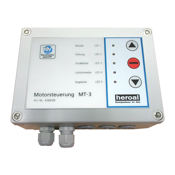
- Seite 1 Betriebs- und Montageanleitung Motorsteuerung MT-3 Instruction for Installation Motor Control MT-3 Mode d´emploi & instruction de montage pour boîtier de commande MT-3 Failure...
-
Seite 2: Inhaltsverzeichnis
Programmation de la diode commutatrice (DIP) Layout Motorsteuerung MT- 3 Layout Motor Control MT-3 Schéma de circuit - boîte de commande MT-3 LED Anzeige auf der Leiterplatte LED Display on the Circuit Board Affichage DEL sur la carte à circuit imprimé... -
Seite 3: Allgemeines - Preface - Généralités
Die Relaisausgänge sind mit einem Maximalstrom von 4A belastbar. The motor control MT-3 is designed for the operating of rolling doors. The core piece of the system is a microprocessor offering various scopes of application and wiring facilities. The processor actuates all operational sequences. -
Seite 4: Hinweis Der Bundespost References Of The Federal Mail / Bundespost
3 Hinweis der Bundespost - References of the Federal Mail / Bundespost - Remarque de la Bundespost (Poste allemande) Der Frequenzbereich 433,05 MHz - 434,79 MHz ist für Hochfrequenzgeräte für industrielle, wissenschaftliche, medizinische, häusliche und ähnliche Zwecke vorgesehen. Beim Betrieb dieser Funkanlage kann daher kein Schutz vor Störungen durch andere Hochfrequenzgeräte und Funk- anlagen gewährt werden. -
Seite 5: Technische Daten - Technical Specifications - Caractéristiques Techniques
- 10° à + 55° C Température de stockage : - 20° à + 70° C Ouvertures de câble : 5 x PG11 6 Konformitätserklärung - Declaration of Conformity - Déclaration de conformité Die Motorsteuerung MT-3 entspricht: Der Richtlinie 89/336/EWG (EMV-Richtlinie) Der Richtlinie: 73/23/EWG (Niederspannungsrichtlinie) -
Seite 6: Installation - Installation - Installation
7 Installation - Setting up - Installation Die Motorsteuerung MT-3 wird serienmäßig mit Netzkabel und Fronttastatur ausgeliefert. Das Gerät ist nach Anschluss der Motorleitung sofort bereit zur Inbetriebnahme . Es können sowohl 230V Motoren, als auch 400V Motoren mit Wendeschütz angeschlossen werden. Zum Betrieb von 400V Motoren muss die Brücke Klemme 1 &... -
Seite 7: Einsatzbereiche Motorsteuerung Mt
Rolltore mit Rohr- / Getriebemotoren Rollgitter mit Rohr- / Getriebemotoren The new motor control MT-3 is an sophisticated rolling door steering mechanism, complying with the standards of the rolling door industry. All significant and until now planned european standards and directives are contained (Parameterisation is carried out by means of the DIL-switch). -
Seite 8: Anschlussmöglichkeiten - Connectability - Possibilités De Raccordement
Le nouveau boîtier de commande MT-3 est une télécommande moderne de portes roulants satisfaisant à toutes les exigences des fabricants de fermetures. Toutes les normes et directives européennes en vigueur et prévues jusqu´à cette date sont respectées dans leur intégralité (paramétrage par commutateur DIP). -
Seite 9: Zusatzfunktionen
Zusatzfunktionen Automatisch schließen (einstellbar über Drehschalter auf Grundplatine) Stellung 0 Automatisch Schließen aus Stellung 1 Offenzeit 10 sec. Stellung 2 Offenzeit 20 sec. Stellung 3 Offenzeit 30 sec. Stellung 4 Offenzeit 30 sec. mit Verkürzung auf 4 sec. - Seite 10 Additional Options Automatic close-down (adjustable via turn switch on the motherboard) Position 0 > automatic close-down off Position 1 > release time 10 sec. Position 2 > release time 20 sec. Position 3 > release time 30 sec. Position 4 > release time 30 sec.
-
Seite 11: Inbetriebnahme - Starting-Up - Mise En Service
Fonctions supplémentaires Fermeture automatique (réglable par bouton rotatif sur carte standard) Position 0 > Fermeture automatique désactivée Position 1 > temps d´ouverture 10s Position 2 > temps d´ouverture 20s Position 3 > temps d´ouverture 30s Position 4 > temps d´ouverture 30s, réduction à 4s après dégagement de la cellule photo électrique Position 5 >... -
Seite 12: Programmeinstellung Dil-Schalter 8-Polig
Programm Funktionen der MT-3 eingestellt. „Der Auslieferungszustand ist eingerahmt“. DIL-switches 1 to 8 are used for setting of operation modes of the MT-3. „Initial state is framed“. Les commutateurs DIP 1 à 8 permettent de régler les fonctions de service et de programmation de la boîtier de commande MT3. -
Seite 13: Schaltfunktion Relais 5 (Potentialfrei)
Schaltfunktion Relais 4 (230V) - Switching Funktion Relay 4 - Fonction de commutation relais 4 (230V) (230V) Impuls 2 Sekunden nach einem AUF-Befehl Impulse response 2 seconds after UP-command Impulsion 2 secondes après une commande OUVERT Dauer-Signal 2 Minuten nach jedem AUF-Befehl Signal length 2 minutes after each UP-command Signal permanent pendant 2 minutes après chaque commande OUVERT Blink-Takt solange das Tor läuft... -
Seite 14: Layout Motorsteuerung Mt
12 Layout Motorsteuerung MT- 3 - Layout Motor Control MT-3 - Schéma de circuit - boîtier de commande MT-3 Übersetzung - Translation - Démultiplication Programm Program Diode commutatrice Tastatur Keyboard Clavier „Lernen“ Taste „Configurating“ Button Enregistrement Offenzeit Hold-open time Temps d´ouverture... -
Seite 15: Led Anzeige Auf Der Leiterplatte
13 LED Anzeige auf der Leiterplatte - LED-Display on the Circuit Card - Affichage DEL sur la carte à circuit imprimé LED grün: POWER / Betriebsspannung ist in Ordnung LED rot: LEISTE / Schaltleiste ist betätigt oder defekt LED gelb: FUNK / Kontrolle für den Funkempfang und Lernen / Löschen der Handsender LED green:... -
Seite 16: Led Zustand / Störungs Tabelle
15 LED Zustand / Störungs Tabelle - 15 LED Status / Failure Index - Statut DEL / Tableau défaillance LED 1 grün LED 2 rot LED 3 gelb Zustand / Störung LED 1 green LED 2 red LED 3 yellow Status / Failure DEL 1 vert DEL 2 rouge... -
Seite 17: Handsender - Hand-Held Transmitter - Émetteurs
16 Handsender - Hand-held transmitter - Émetteur 3 5 , 5 Art.-Nr.: 4261 Art.-Nr.: 4262 Art.-Nr.: 4263 Art.-Nr.: 4264 Lernen - Calibrating Procedure - Enregistrement Die Taste LERNEN auf der Leiterplatte bestätigen. Die gelbe LED FUNK geht an. Nun den Hand- sender betätigen. -
Seite 18: Automatische Schließung - Automatic Close-Down - Fermeture Automatique
17 Automatische Schließung - Automatic Close-Down - Fermeture automatique Die automatische Schließung wird mit dem Drehcodierschalter OFFENZEIT auf der Leiterplatte aktiviert. Die entsprechenden Zeiten entnehmen Sie der nachfolgenden Tabelle. Ist die Lichtschranke (Tordurchfahrt) unterbrochen, wird die Offenzeit jeweils erneut gestartet. In der Schalterstellung 4 und 8 hat die Lichtschranke zusätzlich die Funktion, die eingestellte Zeit auf 4 Sekunden zu verkürzen, sobald die Lichtschranke wieder frei wird. -
Seite 19: Notbedienung - Emergency Handling - Régime De Secours
Totmann-Betrieb geschlossen werden. Ist der Fehler beseitigt, schaltet die Steuerung in den Automatik-Betrieb um. Motor Control MT-3 contains an automatic dead-man`s safety system in case of emergency. Once the light barrier or the safety edge is faulty, the door can be closed-down using the dead-man`s button. Once the failure is eliminated the control returns to the automatic mode. - Seite 20 20 Anschlussplan für 400V Motor - Terminal Connection Diagram For a 400V Motor - Schéma de branchement pour moteur 400V Ansteuerung, potenzialfrei Input signal, potential-free Excitation, potentiel libre Netz 230V, 50Hz Grid 230V, 50 Hz Réseau 230V, 50Hz Brücke entfernen remove bridge circuit Motor, potenzialfrei éliminer pont...
- Seite 21 21 Anschlussplan für die Eingänge - Terminal Connection Diagram For the Inputs - Schéma de branchement des entrées Not Stop Bei Verwendung Brücke entfernen Emergency Stop remove bridge circuit Arrêt d´urgence En cas d´utilisation retirer le pont Bei Verwendung Brücke entfernen Stop remove bridge circuit En cas d´utilisation retirer le pont...
-
Seite 22: Notizen - Notes - Notices
Notizen - Notes - Notices... - Seite 23 Notizen - Notes - Notices...
- Seite 24 Henkenjohann GmbH & Co. KG Österwieher Str. 80 D-33415 Verl Tel. +49 (0)52 46-5 07-0 Fax +49 (0)52 46-5 07-2 22 info@heroal.de www.heroal.de...