WAGO 852-111 Installationsanleitung
Quicklinks
Installationsanleitung
852-111 / 852-112
1. Überblick
Die ETHERNET Switches 852-111 und 852-112 sind kompakte,
industrielle Geräte für die Montage auf der 35mm Hutschiene.
Diese Switches dienen zum Anschluss von Netzwerkkomponenten
an das ETHERNET unter industriellen Bedingungen.
852-111 – 5-port 10/100Mbps Industrial Switch.
852-112 – 8-port 10/100Mbps Industrial Switch.
Betriebstemperatur: 0°C ~ 70°C
2. Verpackungsinhalt
• 1 852-111/852-112 Switch
• Hutschienenbefestigung
• Installationsanleitung
Hinweis: Hutschienenbefestigung ist am 852-112 schon befestigt.
3. Hardware Installation
Schritt 1: Switch aus der Verpackung entnehmen.
Schritt 2: Hutschienenbefestigung an 852-111 montieren (Fig.1)
Schritt 3: Anschluss der +18 ~ 30V DC Versorgungsspannung an
den Versorgungsklemmen (Fig. 2 und Fig. 3).
Anschluss der Funktionserde an die Erdungsschraube
Schritt 4: Anschluss der ETHERNET (RJ-45) Netzwerkkabel an den
ETHERNET Switch. An der LNK/ACT LED ist zu sehen,
wenn eine ETHERNET-Verbindung besteht.
4. Befestigung
Die Switches 852-111/852-112 können auf einer horizontalen
oder vertikalen Oberfläche positioniert werden. Es ist Schraub- oder
Hutschienenbefestigung möglich. (Fig. 4 und Fig. 5).
5. Schraubbefestigung
Hinweis: Bei 852-112 bitte die Hutschienenbefestigung vor der
Montage entfernen.
Befestigung ist horizontal und vertikal möglich.
Nutzen Sie die Schablone (Fig. 6) für die Markierungen.
6. RJ-45 Verdrahtung
Die RJ-45 ETHERNET Ports der Switches 852-111/852-112 unter-
stützen Auto-Negotiation und Auto MDI/MDI-X. Diese Funktionen
unterstützen Sie beim Anschluss unterschiedlicher Geräte und Kabel.
Bitte benutzen Sie für einwandfreie Funktion Kategorie 5 ETHERNET
Kabel und Stecker.
Quick Installation Guide
852-111 / 852-112
1. Overview
The 852-111 and 852-112 switches are compact, DIN-railed and
used to expand the ETHERNET to the factory floor or environments
with extreme conditions.
852-111 – 5-port 10/100Mbps Industrial Switch.
852-112 – 8-port 10/100Mbps Industrial Switch.
Operating temperature: 0°C ~ 70°C
2. Package Checklist
Before installing the 852-111/852-112, verify that the package
contains the following items:
• 1 852-111/852-112 Switch
• DIN Rail Kit
• Quick Installation Guide
Note: DIN Rail Kit is already installed with 852-112
3. Hardware Installation Procedure
STEP 1: Remove the device from its packing.
STEP 2: Attach the DIN Rail Kit for the 852-111 (Fig.1)
STEP 3: Connect the +18 ~ 30V DC power to the power terminal
block (Fig. 2 and Fig. 3).
Connect the grounding screw to the ground wire.
STEP 4: Connect the ETHERNET (RJ-45) port to the networking
device. See the LNK/ACT LED to confirm that the
connection is established.
4. Location
The 852-111/852-112 can be placed on a desktop or
horizontal surface, wall-mounted and Din-Rail mounted (Fig. 4 and
Fig. 5).
5. Wall-Mounted Mask
Note: For 852-112 please remove DIN-rail kit before mounting.
The wall-mounted direction can be straight or horizontal.
Place Use 1:1 drawing mask (Fig. 6) for marking.
6. Cabling– RJ-45
The RJ-45 ports on the 852-111/852-112 support auto negotiation
and auto MDI/MDI-X. This feature eliminates the worry of using
specific cable types.
Please use Category 5 cable and Category 5 rated connectors.
Fig. 1: Hutschiene (DIN Rail) 852-111
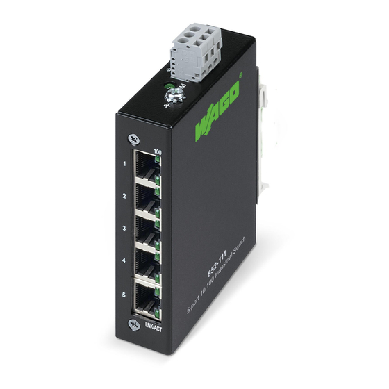
Fig. 2: 852-111
100
1
2
3
Power
4
(green)
Link/Active
Grounding
Screw
5
LNK/ACT
Top View
Front View
Fig. 3: 852-112
LNK/ACT
1
5
Link/Active
(green)
2
6
3
7
+18~30V DC
PWR
4
8
100
+
100Mbps
Grounding
Power
Link/Active
(green)
Screw
(green)
(green)
Front View
100Mbps
(green)
(green)
100
100Mbps
(green)
LNK/ACT

Verwandte Anleitungen für WAGO 852-111


Inhaltszusammenfassung für WAGO 852-111
- Seite 1 STEP 1: Remove the device from its packing. Schritt 3: Anschluss der +18 ~ 30V DC Versorgungsspannung an STEP 2: Attach the DIN Rail Kit for the 852-111 (Fig.1) den Versorgungsklemmen (Fig. 2 und Fig. 3). STEP 3: Connect the +18 ~ 30V DC power to the power terminal Anschluss der Funktionserde an die Erdungsschraube block (Fig.
- Seite 2 Fig. 4: Hutschiene (DIN Rail) 852-111 Fig. 6: 1:1 drawing of 852-111 and 852-112 Mounting holes for INS-8005 and INS-8008 Click Fig. 5: Hutschiene (DIN Rail) 852-112 Mounting Push bracket for Push INS-8008 Bitte kontaktieren Sie bei Fragen den WAGO Kundenservice.