Phoenix Contact RAD-SOL-SET-24-100 Anwenderhandbuch
Solarsystem zur autarken energieversorgung
mit 24 v dc

Inhaltszusammenfassung für Phoenix Contact RAD-SOL-SET-24-100
- Seite 1 Anwenderhandbuch Solarsystem zur autarken Energieversorgung mit 24 V DC User Manual Solar system for autonomous power supply with 24 V DC UM IA RAD-SOL-SET-24-... Artikel-Nr. / Order No. 2699956...
- Seite 2 Anwenderhandbuch Solarsystem zur autarken Energieversorgung mit 24 V DC 2014-03-25 Bezeichnung: UM IA RAD-SOL-SET-24-... Revision: Artikel-Nr.: 2699956 Dieses Handbuch ist gültig für: Bezeichnung Artikel-Nr. RAD-SOL-SET-24-100 2885472 RAD-SOL-SET-24-200 2917722 RAD-SOL-PAN-12-50 2885456 RAD-SOL-BAT-12-40 2885469 RAD-SOL-BAT-12-100 2885498 RAD-SOL-CHG-24-10 2885443 RAD-SOL-BOX-24V 2917353 PHOENIX CONTACT...
- Seite 3 Dieses Symbol und der dazugehörige Text vermitteln zusätzliche Informationen oder verweisen auf weiterführende Informationsquellen. So erreichen Sie uns Internet Aktuelle Informationen zu Produkten von Phoenix Contact und zu unseren Allgemeinen Geschäftsbedingungen finden Sie im Internet unter: phoenixcontact.com. Stellen Sie sicher, dass Sie immer mit der aktuellen Dokumentation arbeiten.
- Seite 4 Bitte beachten Sie folgende Hinweise Allgemeine Nutzungsbedingungen für Technische Dokumentation Phoenix Contact behält sich das Recht vor, die technische Dokumentation und die in den technischen Dokumentationen beschriebenen Produkte jederzeit ohne Vorankündigung zu ändern, zu korrigieren und/oder zu verbessern, soweit dies dem Anwender zumutbar ist.
-
Seite 5: Inhaltsverzeichnis
4.12 Schaltschrank und Solarpanels verdrahten ............47 4.13 Antenne montieren ....................57 4.14 Batterien anschließen..................57 4.15 Abschließende Überprüfung................61 4.16 Zusätzliche Funkmodule/Erweiterungsmodule installieren (optional) ....61 Vorgehensweise beim Ein- und Abschalten................63 Einschalten......................63 Abschalten ......................64 7150_ia_06 PHOENIX CONTACT... - Seite 6 Informationen zur Verbrauchersteuerung ............75 Schutzfunktion..................... 76 Fehleranzeigen....................77 Betrieb ......................... 78 Störungen......................79 8.10 Überwachung der Batteriespannung ..............82 Montage- und Verdrahtungsbeispiel..................83 RAD-SOL-SET-24-100..................83 RAD-SOL-SET-24-200..................85 10 Technische Daten und Bestelldaten ..................87 10.1 Technische Daten ....................87 10.2 Bestelldaten ......................90 Stichwortverzeichnis.........................93...
-
Seite 7: Einleitung
Einleitung Einleitung Die Solarsysteme RAD-SOL-SET-24-100 und RAD-SOL-SET-24-200 von Phoenix Contact sorgen das ganze Jahr über für die zuverlässige Stromversorgung mit 24 V DC. Die in diesem Anwenderhandbuch dargestellten Abbildungen zeigen, wenn nicht beson- ders gekennzeichnet, das Solarsystem RAD-SOL-SET-24-100. Sicherheit Lesen Sie alle Anweisungen vor der Installation und Verdrahtung des Solarsystems sorg- fältig durch. - Seite 8 Installieren Sie trotz der extrem niedrigen Gasung der Batterie keine Funken bilden- den Teile (Schalter, Relais o. Ä.) in unmittelbarer Nähe der Batterie. • Der Betrieb der Batterie an den Betriebstemperaturgrenzen kann (je nach Dauer, Ladezustand etc.) zu einer reduzierten Lebensdauer der Batterie führen. PHOENIX CONTACT 7150_ia_06...
-
Seite 9: Zu Diesem Handbuch
Zu diesem Handbuch Das vorliegende Handbuch enthält Informationen zum Verstehen, Installieren, Betreiben und Bestellen von Teilen für das Solarsystem RAD-SOL-SET-24-.. von Phoenix Contact und von den zugehörigen Komponenten. Die Erklärung der verwendeten Symbole und Signalwörter finden Sie am Anfang dieses Handbuchs. -
Seite 10: Lieferumfang Des Solarsystems
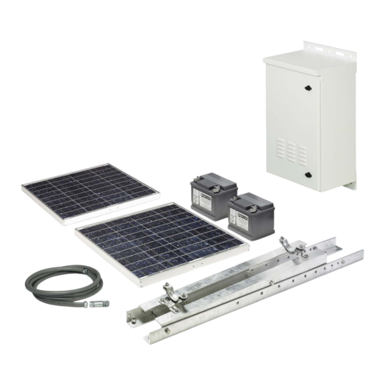
RAD-SOL-SET-24-.. Lieferumfang des Solarsystems Komponenten und Das Solarsystem RAD-SOL-SET-24-.. von Phoenix Contact besteht aus den in Bild 1-1 auf Baugruppen Seite 11 abgebildeten Komponenten und Baugruppen. Das System umfasst die folgenden Hauptkomponenten: – 2 Solarpanels mit je 50 W (nur Solarsystem RAD-SOL-SET-24-100) –... - Seite 11 Einleitung Bild 1-1 Komponenten und Baugruppen des 24-V-Solarsystems RAD-SOL-SET-24-100 7150_ia_06 PHOENIX CONTACT...
-
Seite 12: Komponenten Prüfen
Komponente auf mögliche Transportschäden. Die im Lieferumfang des Solar- systems enthaltenen Artikel sind in Bild 1-1 auf Seite 11 dargestellt. Wenn Sie Schäden ent- decken oder Fragen haben, wenden Sie sich bitte an Phoenix Contact und fragen Sie nach dem Technischen Support für das Solarsystem RAD-SOL-SET-24-... -
Seite 13: Funktion
Einleitung Funktion Bei Sonneneinstrahlung werden die Batterien über zwei Solarpanels (RAD-SOL-SET-24-100) oder vier Solarpanels (RAD-SOL-SET-24-200) und einen Lade- regler aufgeladen. Der Laderegler übernimmt das Batterielade-Management und schützt die Batterien vor Tiefentladung. Die Funkmodule werden aus dem Solarsystem mit einer Spannung von 24 V versorgt. Die Batterien dienen als Pufferspeicher. -
Seite 14: Leistung Des Solarsystems
Maximale Anschlussleistung bei Dauerbetrieb: 120 mA x 24 V = 2,88 W GPRS-Betrieb (dauerhafte TCP/IP-Verbindung im Mobilfunknetz) 210 mA Stromschleife Analogkanal 20 mA 230 mA Maximale Anschlussleistung bei Dauerbetrieb: 230 mA x 24 V = 5,52 W PHOENIX CONTACT 7150_ia_06... -
Seite 15: Lagerung
Kurzschluss und Verlagerung zu sichern. Palettierte Solarpanels und Batterien dürfen nicht gestapelt werden. Die Lagerzeit von Batterien sollte so kurz wie möglich gehalten werden. Die optimale La- gertemperatur beträgt 20 °C. Abweichende Temperaturen verringern die verfügbare Ka- pazität der Batterie. 7150_ia_06 PHOENIX CONTACT... - Seite 16 RAD-SOL-SET-24-.. PHOENIX CONTACT 7150_ia_06...
-
Seite 17: Standort
Standort Standort Sonneneinstrahlung Um die Energieversorgung Ihrer Applikation zu gewährleisten, ist es wichtig, dass das Solarsystem RAD-SOL-SET-24-.. ausreichend Energie liefert. Bild 3-1 Maximale Anschlussleistung bei ganzjähriger konstanter Belastung in Ab- hängigkeit von der Gangreserve 7150_ia_06 PHOENIX CONTACT... - Seite 18 RAD-SOL-SET-24-.. Tabelle 3-1 Maximale Anschlussleistung bei ganzjähriger konstanter Belastung in Abhängigkeit von der Gangreserve RAD-SOL-SET-24-100 RAD-SOL-SET-24-200 Region Globale Einstrahlung Gangreserve Gangreserve [kWh/m /Tag] 2 Tage 3 Tage 4 Tage 5 Tage 2 Tage 3 Tage 4 Tage 5 Tage 1,3 W...
- Seite 19 * Solarmodule in Richtung Süden, Neigung 60°, Ganzjahresbetrieb Beispiel 2: Spanien (Madrid) Tabelle 3-3 Maximale Anschlussleistung im Winter bei konstanter Belastung und einer Gangreserve von ca. vier Tagen RAD-SOL-SET-… …-24-100 …-24-200 3,8 W 10 W * Solarmodule in Richtung Süden, Neigung 60°, Ganzjahresbetrieb 7150_ia_06 PHOENIX CONTACT...
-
Seite 20: Sonnengang Auf Ungehinderte Einstrahlung Prüfen
18.00 Uhr sowohl im Sommer als auch im Winter nicht behindert wird. Beachten Sie dabei auch die Beschattung durch zukünftige Gebäude oder Baumwuchs. 7150B007 Bild 3-2 Prüfung des Sonnengangs im Sommer und Winter auf ungehinderte Einstrahlung PHOENIX CONTACT 7150_ia_06... -
Seite 21: Solarpanels Ausrichten
Leistungsausbeute zu erhalten. Der Neigungswin- kel ist abhängig von der geographischen Breite des Solarsystem-Standorts. Vor dem Ein- stellen des Neigungswinkels müssen Sie sich daher über den Breitengrad Ihres Standorts informieren. Verwenden Sie zur Bestimmung des geeigneten Neigungswinkels die fol- gende Grafik. 7150_ia_06 PHOENIX CONTACT... - Seite 22 RAD-SOL-SET-24-.. Bild 3-4 Neigungswinkel der Solarpanels PHOENIX CONTACT 7150_ia_06...
-
Seite 23: Installation
Allgemeines Dieses Kapitel enthält Informationen zur Installation des Solarsystems RAD-SOL-SET-24-.. von Phoenix Contact. Machen Sie sich vor der Installation mit den Bezeichnungen der Komponenten (siehe Kapitel 1, „Einleitung“) und den Voraussetzungen für die Ausrichtung der Solarpanels (siehe Kapitel 3, „Standort“) vertraut. -
Seite 24: Sicherheitsmaßnahmen
WARNUNG: Gefahr durch elektrische Übergangswiderstände und mechanische Überbeanspruchung Im Betriebsleben des Solarsystems kann es aufgrund von Umwelteinflüsse zur Verände- rungen an den mechanischen und elektrischen Anschlüssen kommen. Kontrollieren Sie alle mechanischen und elektrischen Anschlüsse auf festen Sitz und/oder Beschädigung. PHOENIX CONTACT 7150_ia_06... -
Seite 25: Werkzeug Und Nützliche Geräte
Sie auf Seite 88 und Seite 89 in diesem Handbuch. Der Errichter der Anlage ist für die ordnungsgemäße Montage und Installation des Solar- systems verantwortlich. Der Betreiber der Analge ist für die Standortwahl (z. B. Wasserschutzgebiet) verantwort- lich. Hierzu sind die regionalen Vorschriften zu beachten. 7150_ia_06 PHOENIX CONTACT... -
Seite 26: Schaltschrank Installieren
Entfernen Sie mit einem geeigneten Werkzeug die vier Sicherungsmuttern der Filter- mattenkassette. • Entfernen Sie die Filtermattenkassette von den Gewindebolzen. • Stecken Sie das Abdeckblech mit integrierter Dichtung lagerichtig auf die Gewindebol- zen. • Befestigen Sie das Abdeckblech mit den vier Sicherungsmuttern. 7150A036 Bild 4-1 Abdeckblech montieren PHOENIX CONTACT 7150_ia_06... - Seite 27 Sommermonaten zur Mittagszeit im Schatten der Solarpanels befin- det. Zum Schutz gegen unbefugte Zugriffe ist der Schaltschrank mit zwei Schließvorrichtun- gen ausgerüstet. Diese Schließvorrichtungen können zusätzlich mit Vorhängeschlössern (Bügeldurchmesser 7 mm und 9 mm) gesichert werden. Die Vorhängeschlösser sind nicht im Lieferumfang enthalten. 7150_ia_06 PHOENIX CONTACT...
- Seite 28 Solarpanel-Halterung für Mastmontage Mastschelle Solarkabel 10 Schaltschrank 11 Schaltschrankelektronik 12 Batterien 13 Kabeleinführungen für Solarkabel (M20) 14 Funktionserde (FE) 15 Kabelschuh für Schaltschrankerdung 16 Überspannungsschutz für Antennen (nicht im Lieferumfang enthalten) 17 Montagemast (76 mm Durchmesser) Bild 4-2 Montagebeispiel PHOENIX CONTACT 7150_ia_06...
- Seite 29 Installation RAD-SOL-PAN... Bild 4-3 Verdrahtungsplan für das Solarsystem 7150_ia_06 PHOENIX CONTACT...
- Seite 30 15 Antennen-Überspannungsschutz mit N-Stecker (CN-LAMBDA/4-5.9-BB, Artikel-Nr. 2838490, nicht im Lieferumfang enthalten) 16 Batterien 12 V 17 Kabelschuh, 16 mm für M6 Gewindebolzen Montagemöglichkeiten Bild 4-4 Schaltschrankmontage Schaltschrank für Wandmontage, Montage auf Wandfläche Schaltschrank für Wandmontage, Montage mit Durchgangsbohrungen Schaltschrank für Mastmontage PHOENIX CONTACT 7150_ia_06...
-
Seite 31: Solarsystem Erden
Für den Erdungsanschluss empfehlen wir ein Erdungskabel mit einem Querschnitt von 16 mm (nicht im Lieferumfang enthalten). Legende zu Bild 4-5: Unteres Schaltschrankfach Erdungsanschluss Erdungskabelschuh, 16 mm für M6-Gewindebolzen (nicht im Lieferumfang enthalten) Mutter (1 x) Funktionserde (FE), Kabel 16 mm (nicht im Lieferumfang enthalten) 7150_ia_06 PHOENIX CONTACT... - Seite 32 RAD-SOL-SET-24-.. Bild 4-5 Erdungsanschluss am Schaltschrank PHOENIX CONTACT 7150_ia_06...
-
Seite 33: Sicherungen Entfernen
Sicherungsklemme mit G-Sicherung 5x20, - F1, 125 V, F10 A (Solarpanel) Sicherungsklemme mit G-Sicherung 5x20, - F2, 125 V, F10 A typisch (Batterien) Sicherungsklemme mit G-Sicherung 5x20, - F3, 125 V, F2 A (Verbraucher) Deckelhalterung (2 x) Schraubkappe für Sicherungsklemme U-Profil-Schutzdeckel Befestigungsschrauben (2 x) 7150_ia_06 PHOENIX CONTACT... - Seite 34 RAD-SOL-SET-24-.. Bild 4-6 Sicherungen für Solarpanel, Batterien und Verbraucher PHOENIX CONTACT 7150_ia_06...
-
Seite 35: Überspannungsschutz Für Antennenkabel Installieren
Kabelschuh, 1,5 mm bis 2,5 mm Antennen-Überspannungsschutz 10 Unteres Schaltschrankfach 11 Sicherungsscheibe 12 Sechskantmutter, M20 13 Erdungskabelschuh, 16 mm für Gewindebolzen M6 (nicht im Lieferumfang enthalten) 14 Mutter 15 Funktionserde (FE), Kabel 16 mm (nicht im Lieferumfang enthalten) 7150_ia_06 PHOENIX CONTACT... - Seite 36 RAD-SOL-SET-24-.. Bild 4-7 Überspannungsschutz installieren PHOENIX CONTACT 7150_ia_06...
-
Seite 37: Funkmodul Und Antennenadapter Installieren (Beispiel)
Funkmodul (nicht im Lieferumfang enthalten) Antennenadapter (nicht im Lieferumfang enthalten) Tragschiene NS 35 Würgenippel geschlossen, M20 Antenneadapterkabel (nicht im Lieferumfang enthalten) Dichtung Oberes Schaltschrankfach Sechskantmutter M20 10 Flügelmutter 11 Antennenadapterkabel (nicht im Lieferumfang enthalten) 12 Antennen-Überspannungsschutz (nicht im Lieferumfang enthalten) 7150_ia_06 PHOENIX CONTACT... - Seite 38 RAD-SOL-SET-24-.. Bild 4-8 Funkmodul und Antennenadapter installieren PHOENIX CONTACT 7150_ia_06...
- Seite 39 Installation Beispiel für einen Montageaufbau RAD-SOL-SET-24-100 Legende: Solarpanel Antenne Antennenkabel Solarkabel Schaltschrank Schaltschrankelektronik Batterien Überspannungsschutz Montagemast 10 Funktionserde (FE) Bild 4-9 Beispiel für einen typischen Montageaufbau eines Solarsystems RAD-SOL-SET-24-100 7150_ia_06 PHOENIX CONTACT...
- Seite 40 RAD-SOL-SET-24-.. Beispiel für einen Montageaufbau RAD-SOL-SET-24-200 Legende: Solarpanel Antenne UV-stabilisierter Kabelbinder Antennenkabel Montagehalterung für Solarpanels Schaltschrank mit Elektronik Batterien Überspannungsschutz Solarkabel 10 Montagemast 11 Funktionserde (FE) Bild 4-10 Beispiel für einen typischen Montageaufbau eines Solarsystems RAD-SOL-SET-24-200 PHOENIX CONTACT 7150_ia_06...
-
Seite 41: Solarpanels Installieren
Versuchen Sie nicht, die Modulleistung zu steigern, indem Sie die Lichtkonzentration auf der Solarpanel-Oberfläche erhöhen. • Befestigen Sie die Solarpanel-Halterung mit den beiden Masthalterungen lose in der gewünschten Höhe am Montagemast (siehe Abbildungen auf den folgenden Seiten). 7150_ia_06 PHOENIX CONTACT... - Seite 42 RAD-SOL-SET-24-.. 4.11.1 RAD-SOL-SET-24-100 Bild 4-11 Montage der Solarpanels RAD-SOL-SET-24-100 Bild 4-12 Montage der Schienen RAD-SOL-SET-24-100 PHOENIX CONTACT 7150_ia_06...
- Seite 43 Installation 4.11.2 RAD-SOL-SET-24-200 Bild 4-13 Montage der Solarpanels RAD-SOL-SET-24-200 Bild 4-14 Schienen RAD-SOL-SET-24-200 7150_ia_06 PHOENIX CONTACT...
- Seite 44 Verschrauben Sie die Querleisten (3 und 4 in Bild 4-15) in den entsprechenden Lö- chern der Winkelleisten (5 und 6), um den Neigungswinkel der Solarpanels einzustel- len. Legende: Halteleiste links Halteleiste rechts Querleiste links Querleiste rechts Winkelleiste links Winkelleiste rechts Distanzplatte Bild 4-15 Solarpanels RAD-SOL-SET-24-100 PHOENIX CONTACT 7150_ia_06...
- Seite 45 Der Neigungswinkel der Solarpanels kann im Bereich von 45° bis 75° in Schritten von 5° verstellt werden (siehe auch Kapitel „Neigungswinkel der Solarpanels“ auf Seite 21). Neigungswinkel im Bereich von 45° bis 68° bieten u. a. eine optimale Selbstreinigung von verschattendem Laub, Schnee, Schmutz und Vogelkot. Bild 4-16 Verstellung des Neigungswinkels 7150_ia_06 PHOENIX CONTACT...
- Seite 46 Rahmen der Solarpa- nels oder die Halterung an (siehe Bild 4-17). Verbinden Sie das Kabel mit einem geeig- neten Erdungspunkt. Bild 4-17 Beispiel: Erdung eines Solarpanels bei Montage an einen nicht leitenden Montagemast Legende: Unterlegscheibe Kabel, 6 mm Klemmschraube PHOENIX CONTACT 7150_ia_06...
-
Seite 47: Schaltschrank Und Solarpanels Verdrahten
Systemeigenschaften nicht zulässig. • Verlegen Sie das Solarkabel so, dass keine Gefahr (z. B. Stolpergefahr) davon aus- geht. Phoenix Contact empfiehlt zur Fixierung des Solarkabels UV-stabilisierte Ka- belbinder (siehe Kapitel „Bestelldaten des Zubehörs“ auf Seite 90). • Der Betrieb des Solarpanels mit beschädigten Anschlussleitungen ist nicht zulässig. - Seite 48 RAD-SOL-SET-24-.. Legende: Bohrungsabdichtung Solarkabel, 4 mm² Kontermutter Leitungsdurchführung (M20) Klemmmutter 7150D020 Bild 4-18 Anschluss der Leitungsführung am Schaltschrank PHOENIX CONTACT 7150_ia_06...
- Seite 49 • Kürzen Sie das Kabel auf die erforderliche Länge und versehen das Kabelenden mit ei- ner Aderendhülse. • Verdrahten Sie das Solarkabel gemäß dem Verdrahtungsplan in Bild 4-3 auf Seite 29. Bild 4-19 Leitungsführungen innerhalb des Schaltschranks 7150_ia_06 PHOENIX CONTACT...
- Seite 50 Antennen-Adapterkabel (nicht im Lieferumfang enthalten) Antennen-Überspannungsschutz (nicht im Lieferumfang enthalten) • Montieren Sie den Anschluss der Leitungsführung an der Solarpanel-Seite gemäß Bild 4-3 auf Seite 29. • Führen Sie die Leitungen von der Leitungsführung zu den Anschlussdosen der Solar- panels. PHOENIX CONTACT 7150_ia_06...
-
Seite 51: Anschlussdosen Der Solarpanels Verdrahten
(z. B. Solarkabel mit Pluspotenzial – rotes Isolierband, Solarkabel mit Minuspo- tenzial – blaues Isolierband*). • Beachten Sie die Polarität der Solarkabel und Anschlussklemmen. • Beachten Sie die Anschlussreihenfolge. * verschiedene Kennzeichnungsvarianten möglich Beachten Sie unbedingt die mitgelieferte Bedienungsanleitung des Solarpanel-Herstel- lers. 7150_ia_06 PHOENIX CONTACT... - Seite 52 Solarkabel (Minuspotenzial) Solarkabel (Pluspotenzial) • Die Anschlussdose befindet sich auf der Unterseite des Solarpanels. • Lösen Sie jeweils die Schraube im Deckel der Anschlussdosen und öffnen diese (siehe Bild 4-21). Bild 4-21 Anschlussdose des Solarpanels Legende: Deckel Anschlussraum PHOENIX CONTACT 7150_ia_06...
- Seite 53 Leitungsdurchführungen montieren • Schrauben Sie den Deckel auf der Anschlussdose fest. • Schließen Sie den Deckel der Anschlussdose. • Ziehen Sie alle Klemmschrauben der Leitungsführungen fest, um eine sichere Zugent- lastung und eine wasserdichte Leitungsdurchführung zu gewährleisten 7150_ia_06 PHOENIX CONTACT...
- Seite 54 RAD-SOL-SET-24-.. Anschlussbeispiel RAD-SOL-SET-24-100 102481C009 Bild 4-23 Prinzipdarstellung RAD-SOL-SET-24-100 Legende: Solarpanel Solarkabel (Minuspotenzial zum Schaltschrank) Solarkabel (Pluspotenzial zum Schaltschrank) PHOENIX CONTACT 7150_ia_06...
- Seite 55 Solarkabel (Minuspotenzial zum Schaltschrank) Solarkabel (Pluspotenzial zum Schaltschrank) Photovoltaik-Steckverbinder-Set, bestehend aus Buchse (-) und Stift (+) Photovoltaik-Y-Verteiler, 1 x Buchse (+) - 2 x Stift (-) Photovoltaik-Y-Verteiler, 1 x Stift (-) - 2 x Buchse (+) Solarkabel 7150_ia_06 PHOENIX CONTACT...
- Seite 56 Schieben Sie den Einsatz in die Hülse. • Ziehen Sie die Kabelverschraubung mit 3 Nm an. Sie benötigen einen Schlitzschrau- bendreher mit 3 mm breiter Klinge (z. B. SZF 1-0,6X3,5, Artikel-Nr. 1204517). Weitere Information finden Sie in der Packungsbeilage der SUNCLIX-Photovoltaik-Steck- verbinder. PHOENIX CONTACT 7150_ia_06...
-
Seite 57: Antenne Montieren
Antenne montieren Montieren Sie die Antenne nach den Vorgaben in der Packungsbeilage Ihrer Antenne. Phoenix Contact bietet eine Auswahl an Antennenlösungen an (für weiterführende Informa- tionen siehe Kapitel „Bestelldaten“ auf Seite 90 oder unter phoenixcontact.net/products) Das Antennenkabel wird mit dem Überspannungsschutz im Schaltschrank des Solarsys- tems verbunden. - Seite 58 Vergewissern Sie sich, dass die Leitungen korrekt gepolt sind. • Achten Sie auf einen festen Sitz der Anschlussleitungen. 4.14.1 RAD-SOL-SET-24-100 • Stecken Sie ggf. die Polklemmen [8] auf die Pole der Batterie 1 [9] und Batterie 2 [10] und schrauben diese mit einem Maulschlüssel fest.
- Seite 59 Installation Bild 4-25 Batterien installieren RAD-SOL-SET-24-100 7150_ia_06 PHOENIX CONTACT...
- Seite 60 Schließen Sie die Leitung [2] an den Minuspol der Batterie 2 an und ziehen Sie diese mit einem Maulschlüssel fest. Legende zu Bild 4-26: Leitung vom positiven Pol der Batterie Leitung vom negativen Pol der Batterie Kabelschuh Blei-Gel-Batterie, 12 Volt Verbindungsleitung (Kabelbrücke) Bild 4-26 Batterien installieren RAD-SOL-SET-24-200 PHOENIX CONTACT 7150_ia_06...
-
Seite 61: Abschließende Überprüfung
4.16 Zusätzliche Funkmodule/Erweiterungsmodule installieren (optional) Montieren Sie die zusätzlichen Module nach den Herstellervorgaben. Phoenix Contact bie- tet eine Vielzahl von Messumformern an (für Informationen siehe Kapitel „Bestelldaten“ auf Seite 90 oder unter phoenixcontact.net/products). WARNUNG: Gefahr durch elektrische Spannung an den Solarpanels Solarpanels können gefährliche Spannungen erzeugen, sobald sie dem Sonnenlicht aus-... - Seite 62 RAD-SOL-SET-24-.. PHOENIX CONTACT 7150_ia_06...
-
Seite 63: Vorgehensweise Beim Ein- Und Abschalten
Nach dem Herstellen sämtlicher Leitungsverbindungen für Solarpanels, Batterien und Ver- braucher und Sicherstellen der richtigen Polarität können Sie das System durch Einsetzen der drei Sicherungen wie folgt beschrieben einschalten (siehe Bild 5-1 auf Seite 63). Bild 5-1 Sicherungen für Solarpanels, Batterien und Verbraucher 7150_ia_06 PHOENIX CONTACT... -
Seite 64: Abschalten
Entfernen Sie zum Abschalten des Systems als erstes die Sicherung für die Solar- panels (3 in Bild 5-1). • Entfernen Sie dann die Sicherungen für die Batterie (4 in Bild 5-1) und für die Verbraucher (5 in Bild 5-1). Dadurch werden die Spannungsquellen vom Stromkreis getrennt. PHOENIX CONTACT 7150_ia_06... -
Seite 65: Wartung
Bei einer ggf. vorhandenen Verschmutzung ist das Kunststoffgehäuse der Batterie nur mit Wasser zu säubern. Die Batteriepole auf Korrosion. Verwenden Sie Polfette zum Schutz vor Korrosion nur im angemessenen Maße. Der Betrieb des Solarsystems mit einer beschädigten Batterie ist nicht zulässig. 7150_ia_06 PHOENIX CONTACT... - Seite 66 RAD-SOL-SET-24-.. PHOENIX CONTACT 7150_ia_06...
-
Seite 67: Abbau Des Solarsystems
Verwenden Sie nur isoliertes Werkzeug. • Lösen Sie die Solarpanel-Anschlussleitungen vorsichtig von den Anschlussklemmen in der vorgegebenen Reihenfolge ab: a) Minuspol - Anschlussleitung (z. B. schwarz*). b) Pluspol - Anschlussleitung (z. B. rot*). * verschiedene Kennzeichnungsvarianten möglich 7150_ia_06 PHOENIX CONTACT... -
Seite 68: Messumformer Demontieren (Optional)
Tragen Sie zum Schutz vor Verletzungen Sicherheitshandschuhe. • Lösen Sie die zwei Masthalterungen des Solarpanels mit einem geeigneten Werkzeug. • Legen Sie das Solarpanel auf einer sauberen kratzfreien Unterlage ab. • Reinigen Sie ggf. das Solarpanel von grobem Schmutz. PHOENIX CONTACT 7150_ia_06... -
Seite 69: Schaltschrank Demontieren
Tragen Sie zum Schutz vor Verletzungen Sicherheitshandschuhe. • Lösen Sie die Masthalterung des Schaltschranks mit einem geeigneten Werkzeug. • Legen Sie den Schaltschrank auf einer sauberen kratzfreien Unterlage ab. • Reinigen Sie ggf. den Schaltschrank von grobem Schmutz. 7150_ia_06 PHOENIX CONTACT... - Seite 70 RAD-SOL-SET-24-.. PHOENIX CONTACT 7150_ia_06...
-
Seite 71: Laderegler
ACHTUNG: Schäden an den Batterien durch Entfernen der Klemmenbrücke Das Solarsystem wird mit zwei Batterien (Trockenbatterie) ausgeliefert. Belassen Sie die bereits eingelegte Klemmenbrücke (9) zum Einstellen des Batterietyps bei Verwendung dieser Batterie unbedingt im Laderegler! Beachten Sie unbedingt die mitgelieferte Bedienungsanleitung des Laderegler-Herstel- lers. 7150_ia_06 PHOENIX CONTACT... -
Seite 72: Sicherheitsmaßnahmen
Installieren Sie trotz der extrem niedrigen Gasung der Batterie keine Funken bilden- den Teile (Schalter, Relais o. Ä.) in unmittelbarer Nähe der Batterie. • Der Betrieb der Batterie an den Betriebstemperaturgrenzen kann (je nach Dauer, Ladezustand etc.) zu einer reduzierten Lebensdauer der Batterie führen. PHOENIX CONTACT 7150_ia_06... -
Seite 73: Laderegler Anschließen
Bild 8-2 Klemmenbrücke (9) ACHTUNG: Schäden am Laderegler durch Kurzschlüsse Schließen Sie keine Leitungen an die Klemme „SEALED OR FLOODED SELECT“ an! • Erden Sie den Minuspol der Batterie, um eine wirkungsvolle Erdung des Solarsystems zu erzielen. 7150_ia_06 PHOENIX CONTACT... -
Seite 74: Led-Anzeige
Batterie halb voll Ladung ein Blinken Batterie fast leer Warnung: LVD, Low (1x pro Sekunde) Voltage Disconnect (Ladung ein) Dauerhaft ein Batterie leer LVD, Low Voltage Dis- connect (Ladung aus) Keine LEDs aus Keine Batterie Ladung aus PHOENIX CONTACT 7150_ia_06... -
Seite 75: Informationen Zur Verbrauchersteuerung
Schalten Sie für den Betrieb mehrerer Gleichstromverbraucher, deren Stromentnahme höher ist als die des Ladereglers mit dem niedrigsten maximalen Verbrauchernenn- wert, nicht mehrere Verbraucherausgänge des Ladereglers parallel. Wenn die Batte- riespannung kleiner oder gleich 23,4 V ist, schaltet der Laderegler bei Inbetriebnahme sofort auf TgS. 7150_ia_06 PHOENIX CONTACT... -
Seite 76: Schutzfunktion
Über- oder Unterladen zu verhindern. Dies ist ein kritischer Fehler. Interner Temperatursensor defekt (LED-Anzeige Batteriezustand: Rot-Gelb-Folge) Die Temperatur des Kühlkörpers ist für einen gefahrlosen Betrieb zu hoch. Trennung des Solar- und des Verbraucheranschlusses Trennung bei Hochspannung (LED-Anzeige Batteriezustand: Rot-Grün-Folge) Die Batteriespannung übersteigt das Regelmaximum des Reglers. PHOENIX CONTACT 7150_ia_06... -
Seite 77: Fehleranzeigen
Kurzschluss am Verbraucher Fehler Selbsttest Rot-Gelb-Grün-Folge Rot-Grün-Folge Die rote und die grüne LED leuchten abwechselnd. Rot&Grün-Gelb-Folge Die rote und die grüne LED leuchten gleichzeitig, dann die gelbe LED, dann wieder die rote und die grüne LED gleichzeitig usw. 7150_ia_06 PHOENIX CONTACT... -
Seite 78: Betrieb
Im Normalbetrieb sollte keine schnelle Änderung der Batteriespannung auftreten. Nach einer Nacht, in der die Batterie entladen wurde, steigt die Spannung tagsüber langsam bis auf den eingestellten Laderegel-Sollwert an. Je nach der aktuellen bzw. vorangegangenen Sonneneinstrahlung können die Batterien den Sollwert erreichen oder nicht. PHOENIX CONTACT 7150_ia_06... -
Seite 79: Störungen
Prüfen Sie, ob alle Leitungen richtig angeschlossen und korrekt festgeklemmt sind. • Prüfen Sie, ob die Polung [+] und [–] der Anschlüsse korrekt ist. • Messen Sie die Leerlaufspannung der Solarpanels und prüfen Sie, ob sie im normalen Bereich liegt (siehe Kapitel „Technische Daten“ auf Seite 87). 7150_ia_06 PHOENIX CONTACT... -
Seite 80: Batteriespannung Zu Hoch
Solarpanels). Die grüne LED Batteriezustand sollte erloschen sein. Messen Sie die Spannung an den SOLAR-Klemmen des Ladereglers (bei weiterhin ab- getrennten Solarpanels). Wenn die Batteriespannung an den SOLAR-Klemmen an- liegt, ist der Laderegler möglicherweise beschädigt. * verschiedene Kennzeichnungsvarianten möglich PHOENIX CONTACT 7150_ia_06... -
Seite 81: Betriebsstörung Des Verbrauchers
Berechnung nicht ausreichend dimensioniert, können Batterien mit höherer Kapazität oder ein größeres Solarpanel verwendet werden. Wenden Sie sich bitte an den Technischen Support von Phoenix Contact, wenn die Berech- nung zeigt, dass Ihr Solarsystem nicht ausreichend dimensioniert ist. Dort erfahren Sie, ob eine Erweiterung der Komponenten zur Erhöhung der Ausgangsleistung Ihres Solar-... -
Seite 82: Überwachung Der Batteriespannung
(z. B. an RAD-AI4-IFS oder RAD-DAIO6-IFS). Das Signal wird dann per Funk zur Empfängerstation übertragen. In der Leitzentrale kann eine Warnschwelle (z. B. bei 24 Volt) weiterverarbeitet werden. Berücksichtigen Sie dabei aber den Eigenstromver- brauch des Messumformers von 19 mA. PHOENIX CONTACT 7150_ia_06... -
Seite 83: Montage- Und Verdrahtungsbeispiel
Montage- und Verdrahtungsbeispiel Montage- und Verdrahtungsbeispiel RAD-SOL-SET-24-100 Bild 9-1 Montagebeispiel RAD-SOL-SET-24-100 Legende: Solarpanels Antenne UV-stabilisierte Kabelbinder Antennenkabel Montagehalterung für Solarpanels Schaltschrank mit Elektronik Batterien Überspannungsschutz Solarkabel 10 Montagemast 11 Funktionserde (FE) 7150_ia_06 PHOENIX CONTACT... - Seite 84 RAD-SOL-SET-24-.. 102481C009 Bild 9-2 Prinzipdarstellung RAD-SOL-SET-24-100 Legende: Solarpanels Solarkabel (Minuspotenzial zum Schaltschrank) Solarkabel (Pluspotenzial zum Schaltschrank) PHOENIX CONTACT 7150_ia_06...
- Seite 85 Montage- und Verdrahtungsbeispiel RAD-SOL-SET-24-200 Bild 9-3 Montagebeispiel RAD-SOL-SET-24-200 Legende: Solarpanels Antenne UV-stabilisierte Kabelbinder Antennenkabel Montagehalterung für Solarpanels Schaltschrank mit Elektronik Batterien Überspannungsschutz Solarkabel 10 Montagemast 11 Funktionserde (FE) 7150_ia_06 PHOENIX CONTACT...
- Seite 86 Solarkabel (Minuspotenzial zum Schaltschrank) Solarkabel (Pluspotenzial zum Schaltschrank) Photovoltaik-Steckverbinder-Set, bestehend aus Buchse (-) und Stift (+) Photovoltaik-Y-Verteiler, 1 x Buchse (+) - 2 x Stift (-) Photovoltaik-Y-Verteiler, 1 x Stift (-) - 2 x Buchse (+) Solarkabel PHOENIX CONTACT 7150_ia_06...
-
Seite 87: 10 Technische Daten Und Bestelldaten
2 Batterien mit je 100 Ah (nur RAD-SOL-SET-24-200) – SunSaver-Solar-Laderegler Phoenix Contact behält sich jegliche Änderungen, die dem technischen Fortschritt dienen, vor. Bitte beachten Sie, dass die Solartechnik einer starken Innovation unterliegt. Aus diesem Grund können die gelieferten Module in Ausführung und Abmessungen, nicht jedoch in der Mindestleistung, von den Angaben in diesem Handbuch abweichen. - Seite 88 15 kg Batterie RAD-SOL-BAT-12-100 Nennspannung 12 V DC Ladeschlussspannung 13,8 V DC ... 14,4 V DC Kapazität 100 Ah Ausführung Gel-Elektrolyt Abmessung (B x H x T) 306 mm x168 mm x 211 mm Gewicht 29,3 kg PHOENIX CONTACT 7150_ia_06...
- Seite 89 Technische Daten und Bestelldaten 10.1.1 Abmessungen des Schaltschranks 4 , 5 7150B004 Bild 10-1 Abmessungen des Schaltschranks (mm) 7150_ia_06 PHOENIX CONTACT...
-
Seite 90: Bestelldaten
RAD-SOL-SET-24-.. 10.2 Bestelldaten 10.2.1 Bestelldaten für das Solarsystem Beschreibung Artikel-Nr. Solarsystem einschließlich RAD-SOL-SET-24-100 2885472 – Schaltschrank mit Elektronik und Laderegler – Solarpanels – Batterien – Solarpanel-Halterung Solarsystem einschließlich RAD-SOL-SET-24-200 2917722 – Schaltschrank mit Elektronik und Laderegler – Solarpanels – Batterien –... - Seite 91 Parabolantenne, Schutzart IP65, Gewinn 19 dBi, linear vertikal, An- RAD-ISM-2400-ANT-PAR-19-0 2867885 schluss N (female), Impedanz 50 Ω, Öffnungswinkel h/v 17°/11° Messumformer Artikel-Nr. MCR-3-Wege-Trennverstärker, mit konfigurierbarem Ein-/Ausgang, zur MINI MCR-SL-U-UI-NC 2865007 galvanischen Trennung und Wandlung von Analogsignalen bis 30 V mit Schraubanschluss, Standardkonfiguration 7150_ia_06 PHOENIX CONTACT...
- Seite 92 Lieferlänge: 1 m Basiselement für Schutzstecker PT, Montage auf NS 35/7,5 und PT-BE/FM 2839282 NS 35/15, Gehäusebreite: 17,5 mm Schutzstecker PT mit Überspannungsgeräteschutz für Stromversorgun- PT 2-PE/S- 24AC-ST 2839318 gen, optische Defektanzeige. Nennspannung: 24 V AC PHOENIX CONTACT 7150_ia_06...
-
Seite 93: A Stichwortverzeichnis
Solarpanels ............46 Prinzipschaltbild............13 Solarsystem ............31 Überspannungsschutz .......... 35 Erweiterungsmodul installieren ........61 Schaltschrank Abmessungen ............89 Installieren............. 26 Funkmodul installieren .......... 37, 61 Mastmontage ............30 Funktion ..............13 Verdrahten ............47 Verdrahtungsplan..........29 Wandmontage............30 7150_ia_06 PHOENIX CONTACT... - Seite 94 Technische Daten ............87 Trennung bei Hochspannung........76 Trennung wegen zu geringer Spannung Siehe LVD (Low Voltage Disconnect) Trockenbatterie ............73 Troubleshooting Siehe Störungen beseitigen Überprüfung, abschließende........61 Überspannungsschutz ..........35 Umgekehrte Polarität Batterie ........76 Umgekehrte Polarität PV..........76 PHOENIX CONTACT 7150_ia_06...
- Seite 96 RAD-SOL-SET-24-.. PHOENIX CONTACT 7150_ia_06...