Herunterladen Inhalt Inhalt Diese Seite drucken
Inhaltsverzeichnis

Werbung

Verfügbare Sprachen

Verfügbare Sprachen

BA 160F/00/a3/04.03
016904-0000
FEC 22
d Betriebsanleitung
e Operating Instructions
f Instructions de mise en service
+
Endress
The Power of Know How
Hauser

Werbung

Inhaltsverzeichnis
loading

Inhaltszusammenfassung für Endress+Hauser FEC 22

  • Seite 1 FEC 22 BA 160F/00/a3/04.03 016904-0000 d Betriebsanleitung e Operating Instructions f Instructions de mise en service Endress Hauser The Power of Know How...
  • Seite 2 d Deutsch Seite 3…21 e English Page 23…41 f Francais Page 43…61...
  • Seite 3: Elektronikeinsatz

    BA 160F/00/de/04.03 Elektronikeinsatz 016904-0000 FEC 22 Betriebsanleitung Endress Hauser The Power of Know How...
  • Seite 4 Kurzanleitung Elektronikeinsatz FEC 22 Kurzanleitung Diese Kurzanleitung ermöglicht dem Fachpersonal den schnellen Standardabgleich. Warnung! Diese Kurzanleitung darf nur von Fachpersonal verwendet werden, das die Betriebs- anleitung BA 160 gelesen und verstanden hat. Warnung! Reset Seite 11 Seite 12 Abgleich unbedeckt...
  • Seite 5: Sicherheitshinweise

    5.3 Abgleich bedeckt ..5.4 Abgleich unbedeckt und bedeckt ..Sicherheitshinweise Der Elektronikeinsatz FEC 22 mit einer Multicap- oder Multicap-T-Sonde darf nur als Bestimmungsgemäße Füllstandgrenzschalter verwendet werden. Er ist nach dem Stand der Technik be- Verwendung triebssicher gebaut und berücksichtigt die einschlägigen Vorschriften.
  • Seite 6: Sicherheitsrelevante Hinweise

    Sicherheitshinweise Elektronikeinsatz FEC 22 Sicherheitsrelevante Hinweise Um sicherheitsrelevante oder alternative Vorgänge hervorzuheben, haben wir die fol- genden Sicherheitshinweise festgelegt, wobei jeder Hinweis durch ein entsprechen- des Piktogramm gekennzeichnet wird. Sicherheitshinweise Symbol Bedeutung Hinweis! Hinweis deutet auf Aktivitäten oder Vorgänge hin, die - wenn sie nicht ordnungsgemäß...
  • Seite 7: Einleitung

    Elektronikeinsatz FEC 22 1 Einleitung 1 Einleitung 1.1 Einsatzbereich Der Elektronikeinsatz FEC 22 und eine Sonde des Multicap-Baukastens bilden den kompakten Füllstandgrenzschalter für die Grenzstanddetektion in Füllgütern. Da der Elektronikeinsaz FEC 22 eine komplette (mikroprozessorgesteuerte) Grenzschaltelektronik beinhaltet, benötigt er keine zusätzlichen Auswertegeräte.
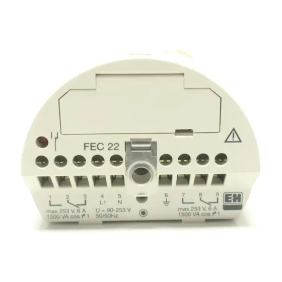
  • Seite 8: Einbau

    Deckel (siehe Abb. 3.1 und 3.2). Ablauf • Drehen Sie den Gehäusedeckel auf. • Stecken Sie den Elektronikeinsatz FEC 22 im Gehäuse in die dafür vorge- sehene Buchse. • Drehen Sie mit einem Schraubendreher die Befestigungsschraube am Elektroni- Abb. 2.1 BA160Y21 Einbau im Sondengehäuse...
  • Seite 9: Bedienung

    Sondengehäuses dicht ist. Hinweis! 4 Bedienung Dieses Kapitel beschreibt die Bedienung des Elektronikeinsatzes FEC 22 am Einsatz- ort. Ein Teil der Anzeigeelemente und die Bedienelemente des Elektronikeinsatzes sind durch eine Abdeckklappe geschützt. Durch einen schlitzförmigen Ausschnitt läßt sich die Abdeckklappe mit einem kleinen Schraubendreher aufklappen. Die Innensei- te der Abdeckklappe ist mit Symbolen bedruckt, die als Kurzanleitung dienen (Erläute-...
  • Seite 10: Bedienelemente

    4 Bedienung Elektronikeinsatz FEC 22 4.1 Bedienelemente Unter der Abdeckklappe befinden sich zwei Tasten und ein Drehschalter. Bedientasten Mit der linken Taste können, je nach Drehschalterstellung, die einzelnen Funktionen ein- oder ausgeschaltet werden oder die entsprechenden Werte der jeweiligen Funk- tion zugeordnet werden (siehe Tabelle 5.1).
  • Seite 11: Rücksetzen Auf Werkseinstellung (Reset)

    Elektronikeinsatz FEC 22 5 Inbetriebnahme 5 Inbetriebnahme Hinweis! Nach jeder Abgleichprozedur (siehe Kapitel 5.2 bis 5.4) ist das Gerät betriebsbereit. Für größtmögliche Betriebssicherheit in kritischen Applikationen empfiehlt sich der Abgleich unbedeckt und bedeckt (siehe Kapitel 5.4). Hinweis! 5.1 Rücksetzen auf Werkseinstellung (Reset) Mit einem Reset werden alle Einstellun- gen am Gerät rückgängig gemacht.
  • Seite 12: Abgleich Unbedeckt Und Bedeckt

    5 Inbetriebnahme Elektronikeinsatz FEC 22 5.2 Abgleich unbedeckt Ablauf • Zum Abgleich einer unbedeckten Sonde drehen Sie den Schalter in die Position 6. • Im Auslieferungszustand bzw. nach einem Reset leuchtet die äußere linke LED in der LED-Reihe: kein Abgleich durchgeführt.
  • Seite 13: Weitere Einstellungen

    Elektronikeinsatz FEC 22 6 Weitere Einstellungen 6 Weitere Einstellungen Dieses Kapitel beschreibt die weiteren Einstellungen, die nach Inbetriebnahme und Abgleich vorgenommen werden können. 6.1 Manuelle Schaltpunktverschiebung Damit der Grenzschalter später auch bei einer Verschmutzung der Sonde zuverlässig Funktion schaltet, haben Sie die Möglichkeit, nach einem erfolgten Abgleich (unbedeckt oder bedeckt) den Schaltpunktabstand ∆C (Werkswert=2 pF) manuell auf 4 pF, 8 pF, 16 pF...
  • Seite 14: Schaltpunktoptimierung

    Neben der manueller Möglichkeit zur Festlegung des Schaltpunktes (siehe Kapitel 6.1) nach einem unbedeckten oder bedeckten Abgleich (siehe Kapitel 5.2, 5.3 und 5.4) bietet der Elektronikeinsatz FEC 22 auch die Möglichkeit zur automatischen Anpas- sung des Schaltpunktes an das Füllgut.
  • Seite 15 Schaltpunktoptimierung einschalten Die Schaltpunktoptimierung kann ausgeschaltet werden (Ablauf siehe Abb. 6.2). Schaltpunktoptimierung Der Elektonikeinsatz FEC 22 arbeitet dann mit der gespeicherten Kapazität (Leerkapa- ausschalten zität C oder Kapazität bei Bedeckung C ) und der ermittelten Schaltpunktkapazität ohne deren Veränderung weiter.
  • Seite 16: Schaltverzögerung

    6 Weitere Einstellungen Elektronikeinsatz FEC 22 6.3 Minimum-/Maximum-Sicherheit Funktion Mit der eingebauten Umschaltmöglichkeit für Minimum-/Maximum-Sicherheit können Sie den Elektronikeinsatz FEC 22 für jeden Anwendungsfall in den erforderlichen Si- cherheitsbetrieb umschalten. Minimum-Sicherheit Maximum-Sicherheit DC-PNP AC-DPDT Rote LED DC-PNP AC-DPDT Rote LED...
  • Seite 17: Service-Modus

    Elektronikeinsatz FEC 22 6 Weitere Einstellungen Schaltverzögerung ∆t ∆t 0,5 s 1,5 s 12 s 20 s bei Bedeckung Ablauf • Drehen Sie den Schalter in die Position 3. • Im Auslieferungzustand bzw. nach einem Reset leuchtet die zweite LED von links in der LED-Rei- he: Verzögerungszeit...
  • Seite 18: Fehlersuche Und -Beseitigung

    7 Fehlersuche und -beseitigung Elektronikeinsatz FEC 22 7 Fehlersuche und -beseitigung Fehlerdiagnose Ursache Maßnahme Grüne und rote LED leuchtet Versorgungsspannung ist aus- Elektrischen Anschluß nicht gefallen oder nicht eingeschaltet überprüfen. Rote LED blinkt Kein Abgleich durchgeführt. Abgleich vornehmen. Gerät arbeitet noch nicht als Grenzschalter.
  • Seite 19: Entsorgung

    • Eine exakte Beschreibung der Anwendung. • Die chemischen und physikalischen Eigenschaften des Produkts. • Eine kurze Beschreibung des aufgetretenen Fehlers. Bevor Sie eine Sonde mit dem eingebauten Elektronikeinsatz FEC 22 zur Reparatur Sonde zurücksenden, ergreifen Sie bitte folgende Maßnahmen: •...
  • Seite 20 Zertifikate und Zulassungen Zertifikate EG-Baumusterprüfbescheinigung KEMA 99 ATEX 3122, XA 060F/00/a3 CE-Zeichen Das Gerät erfüllt die gesetzlichen Anforderungen aus den EG-Richtlinien. Endress+Hauser bestätigt die erfolgreiche Prüfung des Gerätes mit der Anbringung des CE-Zeichens. Bestellinformation Bestell-Nr.: 942299-0000 FEC 22 in Wechselstromausführung Bestell-Nr.: 942299-1000 FEC 22 in Gleichstromausführung...
  • Seite 21 Elektronikeinsatz FEC 22 Index Index Abgleich bedeckt ... . . LED-Reihe ....10 Abgleich unbedeckt .
  • Seite 23 BA 160F/00/en/04.03 Electronic insert 016904-0000 FEC 22 Operating Instructions Endress Hauser The Power of Know How...
  • Seite 24 Quick Guide Elektronic insert FEC 22 Quick Guide This Quick Guide enables trained personnel to quickly carry out the standard calibration procedure. Warning! This Quick Guide may only be used by trained personnel who have read and are thoroughly familiar with the BA 160 Operating Instructions.
  • Seite 25: Inhaltsverzeichnis

    5.4 Calibration when free and covered . . . Notes on Safety The FEC 22 electronic insert is intended for use as a limit switch in combination with Approved Usage the Multicap or Multicap T probe. It has been designed to operate safely in accordance with current technical standards.
  • Seite 26: Safety Conventions

    Safety conventions Elektronic insert FEC 22 Safety Conventions In order to highlight safety-relevant or alternative operating procedures in the manual, the following conventions have been used, each indicated by a corresponding icon in the margin. Safety conventions Symbol Meaning Note! A note highlights actions or procedures which, if not performed correctly, may indirectly affect operation or may lead to an instrument response which is not planned.
  • Seite 27: Introduction

    1 Introduction 1.1 Field of Application The FEC 22 electronic insert is designed as a compact limit switch to be used with the modular family of Multicap probes for limit detection of materials. It contains all the (microprocessor-controlled) electronics necessary for limit detection and does not require an external switching unit.
  • Seite 28: Mounting

    2 Mounting Elektronic insert FEC 22 2 Mounting The FEC 22 can only be mounted in housings F6 (aluminium housing), F10 (plastic housing) and T3 (aluminium housing with separate connection compartment) of the Multicap and Multicap T probes. All housings must have a raised cover (see Fig.
  • Seite 29: Operation

    Note! 4 Operation This section describes how to operate the FEC 22 in the field. One section of the display elements as well as the operating elements of the electronic insert are protected by a cover. This can be raised by inserting a small screwdriver into a recess in it.
  • Seite 30: Operating Elements

    4 Operation Elektronic insert FEC 22 4.1 Operating elements The protective cover houses two keys and a rotary switch. Keys Depending on the position of the rotary switch, the left key switches the individual functions on or off or assigns values to a particular function (see Table 5.1).
  • Seite 31: Commissioning

    Elektronic insert FEC 22 5 Commissioning 5 Commissioning Note! The instrument is on stand-by after each calibration procedure (see Section 5.2 to 5.4). A calibration with both uncovered and covered probe is recommended for critical applications to ensure maximum operational safety (see Section 5.4).
  • Seite 32: Calibration When Free

    5 Commissioning Elektronic insert FEC 22 5.2 Calibration when probe uncovered Procedure • To calibrate an uncovered probe, turn the rotary switch to Position 6. • When first delivered or after a reset the extreme left LED in the chain lights up: no calibration carried out.
  • Seite 33: Additional Settings

    Elektronic insert FEC 22 6 Additional Settings 6 Additional Settings This section describes additional settings which can be carried out after commissioning and calibration. 6.1 Manual switch point adjustment After one calibration (probe uncovered or probe covered), the switch point difference Function ∆C (factory-set value=2 pF) can then be adjusted manually to 4 pF, 8 pF, 16 pF or 32 pF...
  • Seite 34: Switchpoint Optimisation

    Function After a calibration with uncovered or covered probe (see Section 5.2, 5.3 and 5.4) the switch point of the FEC 22 can be set either manually (see Section 6.1) or automatically to adjust to the material being measured. Caution! Switch point optimisation operates only with horizontal probes.
  • Seite 35 Activating switch point optimisation Switch point optimisation can be de-activated (Procedure see Fig. 6.2). Deactivating switch The FEC 22 then operates with the capacitance stored in its memory (capacitance point optimisation when empty C or capacitance when probe covered C...
  • Seite 36: Minimum/Maximum Fail-Safe Mode

    6 Additional Settings Elektronic insert FEC 22 6.3 Minimum/maximum fail-safe mode Function By using the minimum/maximum fail-safe switching feature, the FEC 22 can be used in all applications where a fail-safe function is required. Minimum fail-safe Maximum fail-safe DC-PNP AC-DPDT...
  • Seite 37: Service Mode

    Elektronic insert FEC 22 6 Additional Settings Switching delay ∆t ∆t 0,5 s 1,5 s 12 s 20 s when covered Procedure • Turn the rotary switch to Position 3. • When first delivered or after a reset the LED...
  • Seite 38: Trouble-Shooting And Remedies

    7 Trouble-Shooting and Remedies Elektronic insert FEC 22 7 Trouble-Shooting and Remedies Error diagnosis Cause Remedy Green and red LED do not light up Power supply failure or is not Check electrical connections. switched on Red LED flashes No calibration carried out.
  • Seite 39: Repairs

    • An exact description of the application for which it was used. • The chemical and physical properties of the product measured. • A short description of the fault. Special precautions must be observed when sending the probe and its FEC 22 for Probe repair: •...
  • Seite 40 EC-Type-examination certificate KEMA 99 ATEX 3122, XA 060F/00/a3 CE Mark By attaching the CE Mark, Endress+Hauser confirms that the electronic insert FEC 22 fulfils all legal requirements of the relevant EC directives. Ordering Order No.: 942299-0000 FEC 22 in AC version Order No.: 942299-1000...
  • Seite 41: Index

    Electronic insert FEC 22 Index Index Activating switchpoint optimisation ..Notes on safety ....25 Active build-up compensation ..
  • Seite 43 BA 160F/00/fr/04.03 Electronique 016904-0000 FEC 22 Instructions de mise en service Endress Hauser The Power of Know How...
  • Seite 44 Instructions en bref Electronique FEC 22 Instructions en bref Ces instructions permettent une mise en service rapide par un personnel spécialisé Avertissement Ces instructions s’adressent uniquement au personnel qui a entièrement lu et compris le manuel de mise en service BA 160F.
  • Seite 45 . . . 5.4 Etalonnage sonde recouverte et découverte 52 Conseils de sécurité L’électronique FEC 22 doit uniquement être utilisée avec une sonde Multicap ou Utilisation conforme Multicap T pour la détection de niveau. Elle a été construite selon les derniers acquis à...
  • Seite 46: Conseils De Sécurité

    Conseils de sécurité Electronique FEC 22 Conseils de sécurité Afin de mettre la nature des différentes opérations en évidence, une convention a été établie à l’aide des symboles situés en marge du texte. Conseils de sécurité Symbole Signification Remarque! Ce symbole signale les actions ou procédures susceptibles de perturber indirectement le fonctionnement des appareils ou de générer des réactions imprévues si elles n’ont pas été...
  • Seite 47: Introduction

    1 Introduction 1.1 Domaine d’application L’électronique FEC 22 reliée à une sonde de la famille Multicap constitue un appareil compact pour la détection de niveau de produits divers. Le module piloté par microprocesseur contient tous les éléments électroniques nécessaires à la détection de niveau et ne nécessite pas de transmetteur complémentaire.
  • Seite 48: Montage

    F10 et T3 (avec couvercle surélevé) des sondes Multicap T et Multicap. Procédure • Dévisser le couvercle. • Enficher l’électronique FEC 22 dans le boîtier, sur le connecteur prévu à cet effet. • Serrer la vis de fixation de l’électronique FEC 22.
  • Seite 49: Utilisation

    Remarque! 4 Utilisation Ce chapitre décrit l’utilisation de l’électronique FEC 22 sur site. Une partie des éléments d’affichage et de commande se trouve sous un cache de protection que l’on soulève avec un tournevis. Sur la face intérieure du cache se trouvent les symboles d’instructions de mise en service rapide (voir explications section 5.1).
  • Seite 50: Eléments De Commande

    4 Utilisation Electronique FEC 22 4.1 Eléments de commande Sous le cache se trouvent deux touches et un sélecteur rotatif. Touches de commandes En fonction de la position du sélecteur, la touche de gauche permet d’activer ou de désactiver les diverses fonctions ou d’attribuer les valeurs correspondant aux fonctions (voir tableau 5.1).
  • Seite 51: Mise En Service

    Electronique FEC 22 5 Mise en service 5 Mise en service Remarque! L’appareil est disponible après chaque étalonnage (voir sections 5.2 à 5.4). Pour un maximum de sécurité dans les applications difficiles, il est conseillé de faire un étalonnage avec sonde couverte et découverte (voir section 5.4).
  • Seite 52: Etalonnage Avec Sonde Découverte

    5 Mise en service Electronique FEC 22 5.2 Etalonnage avec sonde découverte Procédure • Mettre le sélecteur en position 6, pour l’étalonnage d’une sonde découverte. • A la livraison, ou après reset, la DEL entièrement à gauche clignote: pas d’étalonnage effectué.
  • Seite 53: Autres Réglages

    Electronique FEC 22 6 Autres réglages 6 Autres réglages Ce chapitre décrit les autres réglages qui peuvent être effectués après la mise en service et l’étalonnage. 6.1 Décalage manuel du point zéro Afin que le détecteur commute avec fiabilité, même lorsque la sonde est encrassée, il Fonction est possible de régler manuellement le décalage du point de commutation ∆C (valeur...
  • Seite 54: Optimisation Du Point De Commutation

    En plus du réglage manuel du point de commutation (voir section 6.1) après un étalonnage avec sonde découverte ou recouverte (voir sections 5.2, 5.3 et 5.4), l’électronique FEC 22 offre également la possibilité d’une adaptation automatique du point de commutation au produit.
  • Seite 55 DEL est allumée: ∆ ∆ optimisation activée. Fig. 6.2 Activation de l’optimisation L’optimisation peut être désactivée (procédure, voir section 6.2). L’électronique FEC 22 Désactivation de fonctionne avec la capacité mémorisée (capacité cuve vide C ou capacité sonde l’optimisation recouverte C ) et la capacité...
  • Seite 56: Sécurité De Fonctionnement Minimum Ou Maximum

    6 Autres réglages Electronique FEC 22 6.3 Sécurité de fonctionnement minimum ou maximum Fonctionnement La commutation intégrée pour la sécurité de fonctionnement minimum ou maximum permet de sélectionner le mode de sécurité pour chaque cas d’application. Sécurité minimum Sécurité maximum...
  • Seite 57: Mode De Maintenance

    Electronique FEC 22 6 Autres réglages Temporisation au ∆t ∆t 0,5 s 1,5 s 12 s 20 s recouvrement Procédure • Tourner le sélecteur en position 3. • A la livraison ou après un reset, la deuxième DEL de gauche est allumée: durée de...
  • Seite 58: Recherche Et Suppression Des Défauts

    7 Recherche et suppression des défauts Electronique FEC 22 7 Recherche et suppression des défauts Diagnostic Cause Remède Aucune DEL allumée Coupure ou absence de tension. Vérifier le raccordement électrique. DEL rouge clignote Aucun étalonnage n’a été Faire l’étalonnage. effectuéFaire l’étalonnage.
  • Seite 59: Réparations

    Electronique FEC 22 9 Réparations 9 Réparations Pour toute électronique FEC 22 renvoyée à Endress+Hauser pour réparations, prière Electronique de joindre une feuille comportant les informations suivantes: • description exacte de l’application • caractéristiques physico-chimiques du produit • brève description du défaut constaté...
  • Seite 60 Numéro de l'attestation d'examen CE de type: KEMA 99 ATEX 3122, XA 060F/00/a3 Sigle CE Par l’apposition du sigle CE, Endress+Hauser certifie que l’électronique FEC 22 répond aux exigences des directives de la CE. Commande Réf. cde 942299-0000 FEC en version courant alternatif Réf.
  • Seite 61: Index

    Electronique FEC 22 Index Index Activation de l’optimisation ..Optimisation du point de commutation ..54 Attribution de valeur ... .
  • Seite 64 Tel. (0 11) 50 31 34 55, Fax (0 11) 50 31 30 67 Belarus Belorgsintez Poland Philippines Canada Minsk ❑ Endress+Hauser Polska Sp. z o.o. ❑ Endress+Hauser Inc. ❑ Endress+Hauser Ltd. Tel. (01 7) 2 5084 73, Fax (01 7) 2 50 85 83 Wroclaw Pasig City, Metro Manila Burlington, Ontario Tel.

Inhaltsverzeichnis