Rittal 4055.040 Bedienungsanleitung

Verwandte Anleitungen für Rittal 4055.040

Inhaltszusammenfassung für Rittal 4055.040
- Seite 1 Elektro-Hydraulikstanze Electric hydraulic punch 4055.040 Montage- und Bedienungsanleitung Assembly and operating instructions...
-
Seite 3: Inhaltsverzeichnis
1 Hinweise zur Dokumentation Inhaltsverzeichnis Hinweise zur Dokumentation Vor Inbetriebnahme lesen und aufbewahren! 1 Hinweise zur Dokumentation ..Mitgeltende Unterlagen....3 1.1 Mitgeltende Unterlagen CE-Kennzeichnung . -
Seite 4: Sicherheitshinweise
2 Sicherheitshinweise Sicherheitshinweise Bestimmungsgemäße Verwendung Achtung! Die Elektro-Hydraulikstanze mit Akku ist bestimmt zum – Beim Bohren des Führungslochs sowie Stanzen von Blechen. beim Stanzen Schutzbrille tragen. Leistungsdaten bis 80 mm Ø Rundlocher – Während des Stanzvorgangs nicht mit den (3,0 mm St. 37; 2,0 mm Chromnickelstahl) Händen in den Stanzbereich eingreifen, da 68 x 68 mm dies zu Quetschungen und Verletzungen... -
Seite 5: Beschreibung
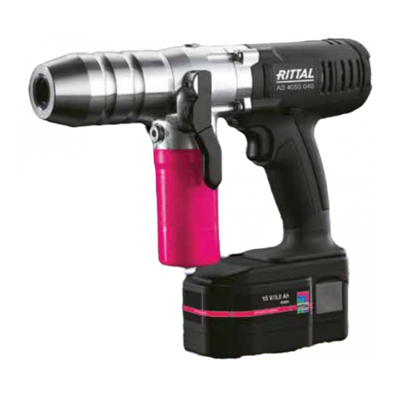
5 Beschreibung Beschreibung Die Elektro-Hydraulikstanze ist ein handgeführtes Ge- rät und besteht aus folgenden Komponenten: Abb. 1: Elektro-Hydraulikstanze Legende Stanzkopf Kopf zur Aufnahme des Zugbolzens einschl. Stempel und Matrize Bedienschalter Auslösung des Stanzvorgangs Rückstellhebel Hebel zur Entlüftung des Stanzkopfes Antrieb Antrieb mit Bedienschalter Akku Wiederaufladbarer 18 V, 3,0 Ah NiMH Akku... -
Seite 6: Stanzen Mit Rund-, Quadrat- Und Rechtecklocher
7 Stanzen mit Rund-, Quadrat- und Rechtecklocher Stanzen mit Rund-, Quadrat- und Hinweis: Rechtecklocher Der Stempel darf nicht innen in der Matrize 1. Vorbohren mit Spiralbohrer oder Mehrstufen- aufsitzen. Dies kann zu Beschädigungen bohrer. am Werkzeug und an der Hydraulikstanze kommen. -
Seite 7: Zugschrauben, Distanzeinsätze, Distanzbuchsen
8 Zugschrauben, Distanzeinsätze, Distanzbuchsen Verfügbare Zugschrauben, Distanzeinsätze und Distanz- buchsen 9,5 mm Best.-Nr. 4055.661 Abb. 5: Anordnung Stempel, Matrize für Quadratlocher 11,1 mm Legende Best.-Nr. 4055.662 Stanzkopf Stanzeinsatz: Stempel 92 x 92 mm, 19 mm Matrize 92 x 92 mm Distanzbuchse Kontermutter Best.-Nr. -
Seite 8: Technische Daten Akku Und Ladegerät
10 Technische Daten Akku und Ladegerät 10 Technische Daten Das Ladegerät ist für eine Spannung von 230 Volt/ 50 HZ ausgelegt. Akku und Ladegerät Akku 18 V, 3,0 Ah NiMH Ladezeit 45 min. nach Vollentladung Ladezyklen ~ 500 bei Normalbedingungen Einsatz 0°C…+ 40°C, Kapazitätsverlust unter 0°C Abb. -
Seite 9: Stanzzeit Und Stanzleistung
12 Stanzzeit und Stanzleistung 12 Stanzzeit und Stanzleistung 15 Entsorgung Die Entsorgung der einzelnen Komponenten muss ge- Stanz- Stanz- trennt erfolgen. Das Öl muss zuerst abgelassen und zeit leistung entsorgt werden. 190 Löcher/ 22,5 mm Ø St. 37 2 mm 5 sec. -
Seite 10: Eg-Konformitätserklärung
16 EG-Konformitätserklärung 16 EG-Konformitätserklärung Montage-, Installations- und Bedienungsanleitung Elektro-Hydraulikstanze mit Akku...