
Verwandte Anleitungen für ersa X-Tool


Inhaltszusammenfassung für ersa X-Tool
- Seite 1 Betriebsanleitung • Operating instructions ERSA X-Tool Die leistungsfähige Entlötstation The powerful desoldering station...
-
Seite 2: Inhaltsverzeichnis
Inhaltsverzeichnis Contents Einführung Introduction Technische Daten Technical Data Sicherheitshinweise Safety information Inbetriebnahme Commissioning Funktionsbeschreibung Functional description Fehlerdiagnose und Error diagnosis and Fehlerbehebung Remedy Wartung und Maintenance Instandhaltung Ersatzteile und Spare parts and Bestelldaten ordering information Garantie Warranty... - Seite 3 11. Vacuum hose 4. DIG 2000 or MIC 60 iA DIG 2000 oder MIC 60 iA 12. Vorfilter control unit 12. Prefilter 5. Fingertaster 5. Finger button 6. Entlötkolben X-Tool 6. X-Tool desoldering iron 7. Restlotbehälter 7. Residual solder container...
- Seite 4 11. Vacuum hose 4. DIG 2000 or MIC 60 iA DIG 2000 oder MIC 60 iA 12. Vorfilter control unit 12. Prefilter 5. Fingertaster 5. Finger button 6. Entlötkolben X-Tool 6. X-Tool desoldering iron 7. Restlotbehälter 7. Residual solder container...
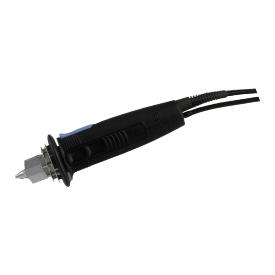
- Seite 5 X-Tool Abbildungen X-Tool Pictures Abb. 2/Fig. 2 Dichtstopfen hinten Lotsammelfilter Solder collection filter Back sealing plug Partikelfilter Dichtstopfen vorne Front sealing plug Particle filter Restlotbehälter Residual solder container...
- Seite 6 / white-green Heizkörper/ blau / blue heating element Ausschnitt X-Tool ohne Griffschale 2 und ohne Lottauffangbehälter / Cut-away of X-Tool with- out handle shell 2 and without solder collection container Ansicht Y / View Y blau / blue schwarz / black...
- Seite 7 X-Tool Abbildungen X-Tool Pictures Abb. 4 a/Fig. 4 a Arretierknopf Gehäuseschraube Griffhälfte Entlötkopf Entlötspitze Locking knob Housing screw Handle half Desoldering head Desoldering tip Abb. 4 b/Fig. 4 b Ventil Arretierknopf Flachsteckverbindungen Ventilstößel Leiterplättchen Heizelemente Valve Locking knob Tab connectors...
-
Seite 8: Einführung
Einführung Introduction Herzlichen Glückwunsch zum Erwerb dieser Congratulations on purchasing this high-tech High-Tech Entlötstation von ERSA. ERSA desoldering station. Sie verwenden diese Gerätekombination vorzugs- We recommend that you use this combination weise zum Entlöten bedrahteter Bauelemente unit for desoldering wired-up components... -
Seite 9: Lieferumfang
• Mains lead • Vorfilter • Prefilter • Ablageständer mit Viskoseschwamm • Holder with viscose sponge • Entlötkolben X-Tool • X-Tool desoldering iron • Reinigungsnadel • Cleaning needle • Ersatz-Restlotbehälter komplett • Spare residual solder container, compl. • Lotsammelfilter 10 Stk. -
Seite 10: Technische Daten
Technische Daten Technical Data Kompressorstation CU 100 A Compressor Unit CU 100 A Spannung/Leistung: Voltage/Power: 230 V~, 50 Hz, 45 W; 115 V~, 60 Hz, 50 W 230 V~, 50 Hz, 45 W; 115 V~, 60 Hz, 50 W Beachten Sie bitte die Angaben auf dem Please refer to the information on the Leistungsschild! rating plate. - Seite 11 Technische Daten Technical Data Entlötgerät X-Tool X-tool desoldering device Spannung: 24 V~ Voltage: 24 V~ Anheizleistung: 260 W Heat up rating: 260 W Anheizzeit: spitzenabhängig Heat up time: tip-dependent Gewicht (inkl. Kabel und Spitze): ca. 240 g Weight (incl. cable and tip): approx. 240 g Heizelemente: zwei Stück à...
-
Seite 12: Sicherheitshinweise
Sicherheitshinweise Safety information Bitte beachten Sie vor der Inbetriebnahme Before commissioning, be sure to note the unbedingt beiliegenden Sicherheitshin- enclosed safety information. weise. -
Seite 13: Inbetriebnahme
Inbetriebnahme Commissioning Compressor Unit CU 100 A Compressor Unit CU 100 A • Netzschalter auf 0 stellen. • Set the power switch to 0. • Vorfilter (Abb.1/Pos. 13) auf den Vakuuman- • Firmly connect the prefilter (fig. 1/no.13) onto schluß (VAC) der Pumpeneinheit CU 100 A the vacuum connection (VAC) of the CU 100 A fest aufstecken. - Seite 14 Inbetriebnahme Commissioning 4.4 Entlötkolben X-Tool 4.4 X-Tool desoldering iron • Prüfen Sie, ob der Lotsammelfilter (Abb. 2/ • Check that the solder collection filter (fig. 2/ Pos.4) sowie der Partikelfilter (Abb. 2/Pos. 2) no. 4)and the particle filter (fig. 2/no. 2) are im Restlotbehälter (Abb.
-
Seite 15: Einschalten
350° C liegen (siehe Kap. 5.1). (see chap. 5.1). Wichtig: Important: Stellen Sie vor jeder Nutzung des Gerätes Each time before you use the unit, make sure sicher, daß alle Original ERSA Filter eingebaut that all genuine ERSA filters are installed. sind! -
Seite 16: Funktionsbeschreibung
Entlötspitzen unterschiedlicher Durchmesser und and quality levels are available for the desolder- Qualität zur Verfügung. Die ERSA Entlötspitzen ing iron. The profile of ERSA desoldering tips sind dem Meniskus der Lötstelle nachgebildet, matches the meniscus of the soldered joint, um so eine optimale Wärmeübertragung zu thereby guaranteeing optimum heat transfer. -
Seite 17: Wechseln Der Entlötspitze
Funktionsbeschreibung Functional description 5.3 Wechseln der Entlötspitze 5.3 Changing the desoldering tip Die Entlötspitze (Abb. 4/Pos. 5) kann mit Hilfe The desoldering tip (fig. 4/no. 5) can be des am Ablageständer befindlichen Spitzen- changed using the tip holder fitted onto the halters gewechselt werden. -
Seite 18: Fehlerdiagnose Und -Behebung
Fehlerdiagnose Error Diagnosis und -behebung and Remedy Entlötleistung ungenügend 6.1 Inadequate desoldering power siehe Kap. 7.1 - „Filter“ see chap. 7.1 - „Filters“ 6.2.1 Pumpe der CU 100 A läuft 6.2 CU 100 A pump starts up häufig an frequently Vakuumsystem ist undicht. -
Seite 19: Entlötspitze Wird Nicht Mehr Heiß
Luftausströmgeräusch hörbar, jedoch kein Vaku- Air escapes audibly but no vacuum available. um vorhanden. Setzen Sie sich bitte mit Ihrem Please contact your local dealer or ERSA direct- Händler oder direkt mit ERSA (Anschrift siehe ly (address see last page). -
Seite 20: Prüfung Der Heizelemente
Fehlerdiagnose Error Diagnosis und -behebung and Remedy 6.4.1 Prüfung der Heizelemente 6.4.1 Testing the heating elements Wird die Entlötspitze nicht heiß, obwohl die Regel- Check both heating elements (fig. 5/no. 3) if the einheit offensichtlich funktioniert, so sollten die desoldering tip does not get hot despite the fact beiden Heizelemente (Abb. - Seite 21 Fehlerdiagnose Error Diagnosis und -behebung and Remedy 6.4.2 Prüfung des 6.4.2 Testing the Thermoelementfühlers thermocouple sensor Wird bei heißer Entlötspitze in der Istwertanzei- An indication of a defect in the thermocouple ge der Regelungseinheit nur eine niedrige, z.B. is that only a low temperature, e.g. room tem- Raumtemperatur, angezeigt, deutet dies auf ein perature, is shown on the actual value display of defektes Thermoelement hin.
- Seite 22 Fehlerdiagnose Error Diagnosis und -behebung and Remedy • Öffnen Sie das Gehäuse (2 Schrauben auf Front- • Use a size 6 Torx driver to open the housing seite, 2 Schrauben im Gehäuseoberteil (Abb.4/ (2 screws on the front panel, 2 screws on the top Pos.
-
Seite 23: Wartung Und Instandhaltung
(fig. 4/no. 1) holding the valve tappet (fig. 4/ stößel (Abb. 4/Pos. 4) hält, eingerastet ist. Eine no. 4) clips in. A spring in the X-Tool handle Feder im X-Tool Griff drückt den Restlotbehälter presses the residual solder container (fig. 2) out (Abb. -
Seite 24: Wechseln Des Lotsammelfilters
Wartung und Maintenance Instandhaltung Vorsicht! Caution! Wenn Sie den Restlotbehälter während des If you remove the residual solder container Betriebes entnehmen, wird die Vorderseite, whilst you are using the unit, the front end of welche mit der Spitze in Berührung stand, the container - which was in contact with the noch heiß... -
Seite 25: Wechseln Des Partikelfilters
Wartung und Maintenance Instandhaltung 7.1.3 Wechseln des Partikelfilters 7.1.3 Changing the particle filter Der Partikelfilter (Abb. 2/Pos. 2) dient dazu, das The particle filter (fig. 2/no. 2) is used for pro- dahinterliegende Ventil (Abb. 4/Pos. 1) sowie tecting the downstream valve (fig. 4/no. 1) as Schläuche und Pumpe vor den Lötdämpfen zu well as the hoses and the pump against solder schützen. -
Seite 26: Wichtige Pflegearbeiten
7.1 Important care jobs Hinweis: Note: Verwenden Sie ausschließlich Original ERSA Only use genuine ERSA consumables and Verbrauchs- und Ersatzteile, um sichere Funk- spare parts in order to ensure reliable function tion und Gewährleistung zu erhalten! and to maintain the unit‘s warranty. - Seite 27 Wartung und Maintenance Instandhaltung • Achten Sie darauf, dass Lüftungsöffnungen • Make certain that the effectiveness of the nicht durch Staubablagerungen ihre Wirkung ventilation holes is not impaired by a verlieren. build-up of dust. • Reinigen Sie mit dem im Zubehör befind- •...
-
Seite 28: Ersatzteile Und Bestelldaten
CU 103 A Compressor unit for CU 100 A, CU 103 A CU 100 A, antistatisch antistatic Entlötkolben X-Tool mit Entlöt- X-Tool desoldering iron with de- 720 EDJ 720 EDJ spitze 722ED12, antistatisch soldering tip 722ED12, antistatic Heizeinsatz für X-Tool... - Seite 29 Venturistation VU 103 A VU 103 A Venturi station VU 103 A VU 103 A für VU 100 A for VU 100 A X-Tool X-Tool ERSADUR desoldering tips ERSADUR-Entlötspitzen 722 EN 0818 722 EN 1529 722 EN 0823...
- Seite 30 ERSA GmbH. Genehmigung der ERSA GmbH reproduziert, übertra- gen oder in eine andere Sprache übersetzt werden. ERSA GmbH • Leonhard-Karl-Str. 24 • 97877 Wertheim / Germany Tel. +49 (0) 9342/800-0 • Fax -100 • e-mail: info@ersa.de • www.ersa.de...