Inhaltsverzeichnis
Werbung
Quicklinks
PICHLER
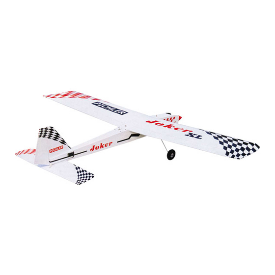
Joker XL
Joker XL
Vorbereitet für Landeklappen.
Factory-prepared for Flaps.
Technische Daten *
Spannweite
Länge
Flächeninhalt
Flächenbelastung
Fluggewicht **
R/C
Servos
Motor
Regler
Akku
* Änderungen und Irrtümer vorbehalten
** Abfluggewicht inklusive Antriebsakku RED POWER 6100-6S
Vorbereitet für den Einbau eines Elektroantriebs
und einer Schleppkupplung für den Seglerschlepp.
Factory-prepared for use of electric motor
and convinient glider towing system.
2120mm
1600mm
75dm²
50g/dm²
3800g
4 -6 Kanal
4 -7
BOOST 80 Brushless
Combo
4250-6100mAh / 22,2V
Anleitung / Manual
R/C Elektromodell /
Electric Powered Model
Specifications *
Wingspan
Length
Wing Area
Wing loading
Flying Weight **
R/C
Servos
Motor
ESC
Akku
* Subject to change without notice
** Flying weight including flight battery RED POWER 6100-6S
95% vormontiert
ARF
ARF
ARF
ALMOST READY TO FLY
2120mm
1600mm
75dm²
50g/dm²
3800g
4 -6 channels
4 -7
BOOST 80 Brushless
Combo
4250-6100mAh / 22,2V
Werbung
Inhaltsverzeichnis

Verwandte Anleitungen für pichler Joker XL


Inhaltszusammenfassung für pichler Joker XL
- Seite 1 PICHLER Anleitung / Manual Joker XL Joker XL R/C Elektromodell / Electric Powered Model Vorbereitet für den Einbau eines Elektroantriebs und einer Schleppkupplung für den Seglerschlepp. Factory-prepared for use of electric motor and convinient glider towing system. Vorbereitet für Landeklappen.
- Seite 2 JOCKER Instruction Manual Dieses ferngesteuerte R/C Flugmodell ist für Anfänger nicht geeignet sondern richtet sich an fortgeschrittene Modellbauer. Trotz sehr hoher Vorfertigung erfordern die Endmontage und der Betrieb des Modells etwas Übung sowie grundlegende Erfahrungen. Wenn Sie unerfahren sind, bitten Sie einen Modellbaukollegen um Hilfe oder fragen Ihren Modellbau-Fachhändler vor Ort. Bevor Sie mit dem Zusammenbau beginnen, prüfen Sie den Inhalt auf Vollständigkeit, Passgenauigkeit bzw.
- Seite 3 ASK-14 Anleitung / Manual Sonderzubehör für Joker XL / Accessories for Joker XL Nachstehendes Zubehör wurde von uns ausgiebig erprobt und wird für beste Flugeigenschaften empfohlen. Weitere Informationen und Bestellmöglichkeit unter www.pichler-modellbau.de These accessories have been extensively tested and are recommended for best flying performance.
-
Seite 4: Safety Precaution
JOCKER Instruction Manual + Do not start the motor if people are near. SAFETY PRECAUTION. Do not stand in line with the side of the propel- + This is not a toy ler. + Be sure that no other flyers are using your + Make motor adjustments from behind the radio frequency. - Seite 5 JOCKER Instruction Manual C/A glue AILERON SERVOS. C/A glue 1.INSTALLING THE AILERON SERVOS. 1) Install the rubber grommets and brass eyelets onto the aileron servos. C/A glue Attention: You can use either 1 or 2 aileron servos per wing panel. Achtung: Sie können entweder 1 oder 2 Querruderservos pro Tragflächenhälfte verwenden.
- Seite 6 JOCKER Instruction Manual 5. Instal servo tray with aileron servo into the wing as same as picture below. C/A glue C/A glue Secure. 2) Using a modeling knife, remove the cov- ering at possition show below. 2.INSTALLING THE AILERON CONTROL HORN. Aileron control horn 3) Using the thread as a guide and using...
- Seite 7 JOCKER Instruction Manual FLAP SERVOS. 1.INSTALLING THE FLAP SERVOS. thread Electric wire. Aileron control horn. 3.INSTALLING THE AILERON LINKAGES. Installing the air brake linkages as pictures below. M3 lock nut. Secure. 115 mm. Repeat the procedure for the other wing half.
- Seite 8 JOCKER Instruction Manual Mark line. 408 mm Flap. Flap Straight line. Control horn. 3.INSTALLING THE FLAP LINKAGES. Installing the air brake linkages as pictures below. Flap. cut. hier trennen Wenn Sie Landeklappen nutzen möchten M3 lock nut. trennen Sie bitte hier das Querruder mit einer feinen Säge.
- Seite 9 JOCKER Instruction Manual INSTALLING THE SPINNER. INSTALLING ELECTRIC MOTOR. Install the spinner backplate, propeller and spinner cone. The spinner cone is held in See picture below: place using two 3mm x 15mm wood screws. Front view. 3 x15mm 3x 15mm Secure.
-
Seite 10: Installing The Battery
JOCKER Instruction Manual INSTALLING THE BATTERY. See picture below: SERVO INSTALLATION. See picture below: 50mm... - Seite 11 JOCKER Instruction Manual A+B Epoxy PLUS glue 3 x 15mm...
- Seite 12 JOCKER Instruction Manual INSTALLING THE MAIN LANDING GEAR. Secure. PARTS REQUIRED 4x15mm 5 x35mm 1. The blind nuts are already mounted in- side the fuselage. M3 lock nut . 2. The holes in the landing gear should be to accept the mounting bolts. 55mm Landing gear.
- Seite 13 JOCKER Instruction Manual 5. A drop of C/A glue on the wheel collar Bottom side. screws will help keep them from coming lose during operation. Repeat the process for the other wheel. Secure. 4. Assemble and mounting the wheel pants as shown in the following pictures.
- Seite 14 JOCKER Instruction Manual Right side. C/A glue Secure. elevator servo right side HORIZONTAL STABILIZER INSTALLA- TION Horizontal stabilize installation . See picture below. Bottom side. C/A glue...
- Seite 15 JOCKER Instruction Manual Bottom side C/A glue C/A glue Bottom side 3x 15mm Top side. Secure. Bottom side. Check to mark sure the wing and stabi- lizer are paralell. If they are not, lightly sand the opening in the fuselage for the stabilizer Top side.
- Seite 16 JOCKER Instruction Manual ELEVATOR CONTROL HORN INSTALLA- Top side. TION. Elevator control horn install as same as the way of aileron control horn. Please see pic- tures below. Elevator control horn. ELEVATOR PUSHROD INSTALLATION. Elevator pushrod install as same as the way of aileron pushrod.
-
Seite 17: Rudder Servo Installation
JOCKER Instruction Manual MOUNTING THE TAIL WHEEL BRACKET. 3x 12mm 1) Set the tail wheel assembly in place on the plywood plate. The pivot point of the tail wheel wire should be even with the rud- der hinge line and the tail wheel bracket should be centered on the plywood plate. -
Seite 18: Vertical Installation
JOCKER Instruction Manual Rudder servo left side VERTICAL INSTALLATION. Vertical stabilizer installation See picture below. 2.Mark the shape of the vertical on the left and right side on the rudder using a felt-tip pen. Mark line. 3.Now, remove the rudder and using a modeling knife, carefully cut just inside the marked lines and remove the film of the rud- 1. - Seite 19 JOCKER Instruction Manual Epoxy glue. Vertical C/A glue. Stabilizer. Horizontal 90º Stabilizer. 4. Put the vertical stabilizer back in place. Using a triangle, check to ensure that the vertical stabilizer is aligned 90 de- gree to the horizontal stabilizer. Epoxy glue.
- Seite 20 JOCKER Instruction Manual C/A glue. Mark point. C/A glue. Carefully make a 90 degree bend down at the mark made. Cut off the excess wire, leaving about 20mm beyond the bend. Bend and cut. A+B Epoxy PLUS glue Push. 20mm.
- Seite 21 JOCKER Instruction Manual 5) When you are sure that everything is a RUDDER CONTROL HORN INSTALLA- aligned correctly, mix up a generous amount TION. of 30 minute epoxy. Apply a thin layer to the slot in the mounting platform and to the verti- Rudder control horn install as same as the cal stabilizer mounting area.
- Seite 22 JOCKER Instruction Manual Do not permanently secure the receiver and RUDDER PUSHROD INSTALLATION. battery until after balancing the model. Rudder pushrod install as same as the way 4. Using a 2mm drill bit, drill a hole through of aileron pushrod. the side of the fuselage, near the receiver, for the antenna to exit.
- Seite 23 JOCKER Instruction Manual Left wing. Right wing. secure. 6x 45 mm wing bolt Secure. Top side...
-
Seite 24: Control Throws
JOCKER Instruction Manual BALANCING. 1) It is critical that your airplane be bal- anced correctly. Improper balance will cause 110mm your plane to lose control and crash. THE CENTER OF GRAVITY IS LOCATED MM BACK FROM THE LEADING EDGE OF Schwerpunkt THE WING.