
Verwandte Anleitungen für Avdel Genesis 07537


Inhaltszusammenfassung für Avdel Genesis 07537
- Seite 1 B e t r i e b s a n l e i t u n g Üb e r s e t z u n g d e r O r i g i n a l - B e t r i e b s a n l e i t u n g ®...
-
Seite 3: Inhaltsverzeichnis
JEGLICHE IMPLIZIERTE GARANTIE IN BEZUG AUF QUALITÄT, EIGNUNG FÜR EINEN BESTIMMTEN ZWECK ODER MARKTGÄNGIGKEIT WERDEN HIERMIT VON AVDEL AUSDRÜCKLICH ZURÜCKGEWIESEN UND AUSGESCHLOSSEN. Im Rahmen der Geschäftspolitik der ständigen Produktentwicklung und -verbesserung behält sich Avdel UK Limited das Recht vor, Spezifikationen ohne vorherige Ankündigung zu ändern. -
Seite 4: Sicherheitsvorschriften
Ausrüstungen verwenden. Für jede vom Kunden durchgeführte Änderung an Gerät/Maschine, Mundstücken, Zubehör und anderen von Avdel UK Limited oder von ihren Vertretern gelieferten Einzelteilen ist der Kunde alleine verantwortlich. Avdel UK Limited wird Sie bei allen geplanten Veränderungen gerne beraten. -
Seite 5: Technische Daten
Te c h n i s c h e D a t e n Te c h n i s c h e D a t e n f ü r G e r ä t Ty p 0 7 5 3 7 Betriebsdruck min./max. -
Seite 6: Arbeitsbereich
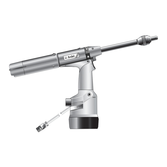
A r b e i t s b e re i c h Das Druckluftgerät 07537 ist ein leichtes Handgerät zum Setzen von Avdel ® Magazinznieten (ausgenommen 1/16% Avlug ® Es eignet sich deshalb ideal für die Serien- und Fließmontage mit den verschiedensten Einsatzzwecken in allen Industriezweigen. -
Seite 7: Inbetriebnahme
I n b e t r i e b n a h m e D r u c k l u f t v e r s o rg u n g Der Betrieb aller Geräte erfolgt durch Druckluft mit einem optimalen Druck von 5,5 bar. Wir empfehlen den Einsatz von Druckreglern und automatischen Öl-/Filtersystemen für die Hauptdruckluftversorgung. -
Seite 8: Mechanische Rücklaufsperre
I n b e t r i e b n a h m e M e c h a n i s c h e R ü c k l a u f s p e r r e FEDERBEAUFSCHLAGTES ENDE LAUF RÜCKLAUFSPERRE... -
Seite 9: Laden Und Nachladen Des Gerätes
Inbetriebnahme R ü c k l a u f s p e r r e WICHTIG Bei falschem Einbau macht die Rücklaufsperre die Zuführung der Niete unmöglich. Obgleich die Rücklaufsperre bei Lieferung des Gerätes richtig herum eingebaut wurde, empfehlen wir vor Anbau der Ausrüstung ihre Einbaulage zu prüfen. -
Seite 10: Laden Des Gerates
Inbetriebnahme L a d e n d e s G e r ä t e s • Die Druckluftversorgung am Gerät anschließen. • Die Spannbacken 34 zum Spannen des Dorns öffnen. Zu diesem Zweck das Schaltventil abschalten (Pos. 22 und 23). •... -
Seite 11: Kennzeichnung Und Lage Der Nietdornfedern
I n b e t r i e b n a h m e KENNZEICHNUNG UND LAGE DER NIETDORNFEDERN BEZEICHNUNG NIETDORN-/NIETDORNFEDERN- MUNDSTÜCK NIETDORN- UND NIETBAUGRUPPE GRÖSSE NIET GRÖSSE (SIEHE ABSCHNITT ÜBER AUSRÜSTUNG) NIETDORNFEDER FEDER UND KAPPENBILDEN EINE EINHEIT NIETDORN NIETDORNKOPF 3 /32"... -
Seite 12: Ausrüstungen
A u s r ü s t u n g e n Auf Magazinnietgeräten wie Modell 0753 Mk II besteht die Ausrüstung stets aus drei Konponenten: einem Mundstück, einem Nietdorn und einer Nietdornfeder. Diese drei Teile müssen zum gesetzten Niet und zum Lochdurchmesser passen. W I C H T I G Um ein vollständiges Zerlegen des Gerätes zu vermeiden, ist es notwendig, die Orientierung der Rücklaufsperre vor Einbau der Ausrüstung zu prüfen (siehe Abschnitt "RÜCKLAUFSPERRE"... -
Seite 13: Auswahl Eines Mundstücks
A u s r ü s t u n g e n A u s w a h l e i n e s M u n d s t ü c k s • Bezeichnung, Größe und Werkstoff des zu setzenden Niets auflisten. STANDARD •... -
Seite 14: Auswahl Des Mundstücks - Zollmass
A u s r ü s t u n g e n A u s w a h l d e s M u n d s t ü c k s - Z o l l m a s s Die Spalte "BEZ.-NR."... -
Seite 15: Auswahl Des Mundstücks - Metrische Masse
A u s r ü s t u n g e n A u s w a h l d e s M u n d s t ü c k s - M e t r i s c h e M a s s e MUNDSTÜCK MUNDSTÜCK BEZ. -
Seite 16: Chobert ® Und Grovit ® - Zollmass
Verantwortung sicherzustellen, daß Nietdorne ersetzt werden, bevor ein übermäßiger Verschleiß auftritt sowie stets vor Erreichen der höchstzulässigen Anzahl von Nietungen. Setzen Sie sich bitte mit Ihrem Avdel UK Limited-Vertreter in Verbindung, der Ihnen den Wert bekanntgeben wird, nachdem er die Setzkraft Ihrer Anwendung mit unserem Prüfgerät zur Setzkraftmessung gemessen hat. -
Seite 17: Chobert
A u s r ü s t u n g e n Die unten links und rechts sowie auf den nächsten vier Seiten abgedruckten Tabellen enthalten eine Auflistung der Teilnummern für alle Nietdorne und Nietdornfedern pro Niet oder Nietengruppe, z.B. für Chobert ®... -
Seite 18: Briv ® - Zollmass
A u s r ü s t u n g e n Um die korrekte Teilnummer eines Nietdorns für eine besondere Anwendung aufzufinden, die nachstehenden Anweisungen lesen, nachdem die Angaben entsprechend dem nebenstehenden Beispiel festgestellt wurden. Die Antworten für das Beispiel sind in grauer Kursivschrift gedruckt. -
Seite 19: Avlug ® , Avsert ® , Avtronic ® Und Rivscrew
A u s r ü s t u n g e n N i e t d o r n k o p f a r t e n u n d L ä n g e “ P ” ®... -
Seite 20: Zollmass Und Metrische Masse
A u s r ü s t u n g e n ® ® ® ® Avlug , Avsert , Avtronic und Rivscrew - Zollmass und Metrische Masse Für die Auswahl von Nietdorn oder Nietdornfeder die Anweisungen auf Seite 18 befolgen. STANDARD-NIETDORN - GRÜN NIETDORN FÜR 1. -
Seite 21: Wartung Des Gerätes
Wartung des Gerätes Die Wartung ist in regelmäßigen Zeitabständen durchzuführen. Eine umfangreiche Prüfung ist jährlich oder alle 500.000 Arbeitstakte durchzuführen, je nachdem, was früher eintritt. W I C H T I G Der Arbeitgeber trägt die Verantwortung, sicherzustellen, daß die Gerätewartungsanweisungen dem entsprechenden Personal ausgehändigt werden. -
Seite 22: Molykote ® 55M Sicherheitsdaten
Wartung des Gerätes ® M o l y k o t e 5 5 m S i c h e r h e i t s d a t e n Erste Hilfe HAUT: Mit Wasser abspülen. Abwischen. EINNAHME: Keine Erste-Hilfe-Maßnahme erforderlich. AUGEN: Mit Wasser ausspülen. -
Seite 23: Werkzeugsatz
Wartung des Gerätes W e r k z e u g s a t z Wir empfehlen die Verwendung der nachfolgenden Werkzeugsätze für alle Wartungsarbeiten. -
Seite 24: Wartung
Wa r t u n g Alle 500 000 Arbeitstakte sollte das Gerät vollständig zerlegt werden. Verschlissene, beschädigte oder andere empfohlene Teile sind zu ersetzen. Alle Dichtringe und Dichtungen sind zu ersetzen und mit Molylithiumfett EP 3753 vor der Montage einzuschmieren. ®... -
Seite 25: Handgriff Und Hintere Kappe
Wa r t u n g Z e r l e g e n 0 7 5 3 7 - 0 0 2 0 0 SPANNBACKENZYLINDER • Mit einem Innensechskantschlüssel* eine Innensechskantschraube 5 entfernen, wobei darauf geachtet werden muß, daß sämtliche eingeschlossene Luft im Spannbackenzylinder abgelassen wurde. -
Seite 26: Übersichtszeichnung Des Grundgerätes
0 7 5 3 7 - 0 0 2 0 0 Übersichtszeichnung des Grundgerätes... - Seite 27 0 7 5 3 7 - 0 0 2 0 0 Ersatzteilliste für Grundgerät...
-
Seite 28: Auffüllen
A u f f ü l l e n Nach dem Zerlegen des Gerätes und vor Inbetriebnahme ist IMMER ein Auffüllen erforderlich. Es kann auch notwendig werden, den vollen Hub nach längerem Gebrauch wiederherzustellen, wenn der Hub geringer geworden ist und Niete nicht vollständig durch einmaliges Betätigen des Auslösers gesetzt werden. -
Seite 29: Auffüllvorgang
A u f f ü l l e n A u f f ü l l v o r g a n g WICHTIG GERÄT VON DER DRUCKLUFTVERSORGUNG ABTRENNEN ODER AM VENTIL 70 ABSCHALTEN. Sämtliche Arbeitsvorgänge sind auf einer sauberen Werkbank, mit sauberen Händen und in einer sauberen Bereich durchzuführen. -
Seite 30: Beseitigen Von Störungen
Wie unter "Nietdornschlupf", Stufe 2, einem Niet. prüfen. Falscher Abstand zwischen Nietkopf und Abstand auf 1,5 - 3 mm einstellen (siehe Mundstück nach dem Laden. "Gerät laden"). ® Andere Symptome oder Störungen sind Ihrem zuständigen Avdel -Händler oder -Reparaturcenter mitzuteilen. -
Seite 31: Ausgabedatum
K o n f o r m i t ä t s e r k l ä r u n g Wir, Avdel UK Limited; Watchmead Industrial Estate, Welwyn Garden City, Hertfordshire, AL7 1LY erklären unter unserer alleinigen Verantwortung, dass das Produkt:... - Seite 32 This document is for informational purposes only. Infastech makes no warranties, expressed or implied, in this document. Data shown is subject to change without prior notice as a result of continuous product development and improvement policy. Your local Avdel representative is at your disposal should you need to confirm latest information.
- Seite 33 I n s t r u c t i o n M a n u a l O r i g i n a l I n s t r u c t i o n ® G e n e s i s 0 7 5 3 7 H y d ro - P n e u m a t i c P o w e r To o l...
- Seite 35 AND REMEDIES. ANY IMPLIED WARRANTY AS TO QUALITY, FITNESS FOR PURPOSE, OR MERCHANTABILITY ARE HEREBY SPECIFICALLY DISCLAIMED AND EXCLUDED BY AVDEL. Avdel UK Limited policy is one of continuous product development and improvement and we reserve the right to change the specification of any product without prior notice.
-
Seite 36: Safety Rules
Any modification undertaken by the customer to the tool/machine, nose assemblies, accessories or any equipment supplied by Avdel UK Limited. or their representatives, shall be the customer’s entire responsibility. Avdel UK Limited. will be pleased to advise upon any proposed modification. -
Seite 37: Tool Dimensions
S p e c i f i c a t i o n s S p e c i f i c a t i o n f o r 0 7 5 3 7 To o l Air Pressure Minimum - Maximum 5-7 bar (70-100 lbf/in Free Air Volume Required... -
Seite 38: Intent Of Use
I n t e n t o f U s e ® ® The pneumatic 07537 tool is a handheld lightweight tool designed to place Avdel speed fasteners (except ” Avlug ) making it ideal for batch or flow-line assembly in a wide variety of applications throughout all industries. -
Seite 39: Putting Into Service
P u t t i n g i n t o S e r v i c e A i r S u p p l y All tools are operated with compressed air at an optimum pressure of 5.5 bar. We recommend the use of pressure regulators and filtering systems on the main air supply. -
Seite 40: Mechanical Cursors
P u t t i n g i n t o S e r v i c e M e c h a n i c a l C u r s o r s SPRING TOOL LOADED END BARREL CURSOR NOSE JAWS... -
Seite 41: Loading And Reloading The Tool
P u t t i n g i n t o S e r v i c e C u r s o r IMPORTANT If fitted incorrectly, the cursor will not allow feeding of the fasteners. While the cursor will be fitted the correct way round when the tool is supplied, we recommend that you check its orientation before fitting the nose equipment. -
Seite 42: Loading The Tool
P u t t i n g i n t o S e r v i c e L o a d i n g t h e To o l • Connect the air supply to the tool. • Open tail jaws 34 which grip the mandrel, by switching off the tail jaw switch (items 22 and 23). -
Seite 43: Mandrel Follower Springs Identification And Orientation
P u t t i n g i n t o S e r v i c e MANDREL FOLLOWER SPRINGS IDENTIFICATION AND ORIENTATION FASTENER MANDREL/MANDREL FOLLOWER SPRING NOSE JAW MANDREL AND FASTENER ASSEMBLY SIZE NAME SIZE (SEE NOSE EQUIPMENT SECTION) MANDREL FOLLOWER SPRING MANDREL HEAD MANDREL... -
Seite 44: Nose Assemblies
N o s e A s s e m b l i e s On speed fastening tools such as 0753 MkII type, the nose equipment always consists of three elements: a nose jaw, a mandrel and a mandrel follower spring. All three items are matched to the fastener being placed and to the hole size in the application. I M P O R T A N T To avoid complete dismantling of the tool it is essential to check the orientation of the cursor before fitting the nose equipment to the tool. -
Seite 45: Selecting A Nose Jaw
N o s e A s s e m b l i e s S e l e c t i n g a N o s e J a w • List the name, size and material of the fastener to be placed. •... - Seite 46 N o s e A s s e m b l i e s N o s e J a w S e l e c t i o n - I m p e r i a l The ‘REF Nº’ column cross references with the ‘REF Nº’ columns in the mandrel section. It identifies both the mandrel and mandrel follower spring required for a particular nose jaw with a specific fastener.
- Seite 47 N o s e A s s e m b l i e s N o s e J a w S e l e c t i o n - M e t r i c NOSE JAW NOSE JAW REF.
-
Seite 48: Mandrels And Mandrel Follower Springs
Contact your Avdel. representative who will let you know what that figure is by measuring the broach load of your application with our calibrated measuring tool. These tools can also be purchased under part number 07900- 09080, supplied with all necessary information for testing. -
Seite 49: And Grovit ® - Metric
N o s e A s s e m b l i e s Tables below left and right and over the next four pages list part numbers of all mandrels and mandrel follower springs available per ® ® fastener or group of fasteners, i.e. for Chobert and Grovit on these pages. -
Seite 50: Briv ® - Imperial
N o s e A s s e m b l i e s To find the correct part number of a mandrel for a particular application, read the instructions below after you have gathered the following information as per example alongside. Answers for the example are shown in grey italic. -
Seite 51: Mandrel Head Types And 'P' Length
N o s e A s s e m b l i e s M a n d r e l H e a d Ty p e s a n d ‘ P ’ L e n g t h Mandrels for stainless steel Briv ®... -
Seite 52: Avlug ® , Avsert ® , Avtronic ® And Rivscrew
N o s e A s s e m b l i e s ® ® ® ® A v l u g , A v s e r t , A v t ro n i c a n d R i v s c r e w - I m p e r i a l a n d M e t r i c For mandrel or mandrel follower spring selection, follow instructions on page 18. -
Seite 53: Servicing The Tool
S e r v i c i n g t h e To o l Regular servicing should be carried out and a comprehensive inspection performed annually or every 500,000 cycles, whichever is sooner. I M P O R T A N T The employer is responsible for ensuring that tool maintenance instructions are given to the appropriate personnel. -
Seite 54: Molykote ® 55M Grease Safety Data
S e r v i c i n g t h e To o l ® M o l y k o t e 5 5 m G r e a s e S a f e t y D a t a First Aid SKIN: Flush with water. -
Seite 55: Service Kits
S e r v i c i n g t h e To o l S e r v i c e K i t s For all servicing we recommend the use of the following service kits. SERVICE KIT : 07900-05300 Spanners are specified in inches and across flats unless otherwise stated. -
Seite 56: Pneumatic Piston Assembly
M a i n t e n a n c e Every 500,000 cycles the tool should be completely dismantled and new components should be used where worn, damaged or when ® recommended. All ‘O’ rings and seals should be renewed and lubricated with Molykote 55m grease for pneumatic sealing or ®... - Seite 57 M a i n t e n a n c e D i s m a n t l i n g 0 7 5 3 7 - 0 0 2 0 0 TAIL JAW CYLINDER • Using an Allen Key*, remove one cap head Screw 5 ensuring that any trapped air in the tail jaw cylinder is exhausted. Remove the second cap head Screw 5.
- Seite 58 G e n e r a l A s s e m b l y o f 0 7 5 3 7 - 0 0 2 0 0 To o l...
- Seite 59 P a r t s L i s t f o r 0 7 5 3 7 - 0 0 2 0 0 To o l...
-
Seite 60: Oil Details
P r i m i n g Priming is ALWAYS necessary after the tool has been dismantled and prior to operating. It may also be necessary to restore the full stroke after considerable use, when the stroke may be reduced and fasteners are not fully placed by one operation of the trigger. O i l D e t a i l s ®... -
Seite 61: Priming Procedure
P r i m i n g P r i m i n g P ro c e d u r e I M P O R T A N T DISCONNECT THE TOOL FROM THE AIR SUPPLY OR SWITCH OFF AT VALVE 70. All operations should be carried out on a clean bench, with clean hands in a clean area. -
Seite 62: Fault Diagnosis
Incorrect gap between fastener head Set gap to 1.5mm - 3mm ( ” - ”) time and nose jaws when loaded See ‘Loading the Tool’ ® Other symptoms or failures should be reported to your local Avdel authorised distributor or repair centre. - Seite 63 D e c l a r a t i o n o f C o n f o r m i t y We, Avdel UK Limited; Watchmead Industrial Estate, Welwyn Garden City, Hertfordshire, AL7 1LY declare under our sole responsibility that the product: Model 07537 Serial No.
- Seite 64 This document is for informational purposes only. Infastech makes no warranties, expressed or implied, in this document. Data shown is subject to change without prior notice as a result of continuous product development and improvement policy. Your local Avdel representative is at your disposal should you need to confirm latest information.