Herunterladen Diese Seite drucken
VMB TL-A150 LINE ARRAY Bedienungsanleitung
Vorschau ausblenden Andere Handbücher für TL-A150 LINE ARRAY:

Werbung

Verfügbare Sprachen

Verfügbare Sprachen

E
GB
D
USA
TL-A150
LINE ARRAY
TOWERLIFT
TORRE ELEVADORA
TRAVERSENLIFT
OPERATING INSTRUCTIONS USER MANUAL
MANUAL DE INSTRUCCIONES
V.07.17

Werbung

loading

Inhaltszusammenfassung für VMB TL-A150 LINE ARRAY

  • Seite 1 TL-A150 LINE ARRAY TOWERLIFT TORRE ELEVADORA TRAVERSENLIFT OPERATING INSTRUCTIONS USER MANUAL MANUAL DE INSTRUCCIONES V.07.17...
  • Seite 2: Made In Spain (Eu)

    LIFTING TOWER TL-A150 TORRE ELEVADORA TL-A150 TRAVERSENLIFT TL-A150 CONTENTS / ÍNDICE Features of the TL-A150 Towerlift / Características TL-A150..... 3 - 4 English Quick operation guide..............5 - 11 Manual de usuario Español................12 - 18 Bedienungsanleitung Deutsch..............19 - 25 Sketches / Planos piezas................
  • Seite 3 TL-A150 F: Forks / Brazos de carga S: Transport compartment / Alojamiento de transporte T: Transport wheels / Ruedas de transporte V: Working compartment / Alojamiento de trabajo PRO LIFTS S.L. Depósito legal y copyright 2014. Todos los derechos reservados.
  • Seite 4 TL-A150 Handle / Manivela Spirit level Force on hand crank / Fuerza sobre manivela Leg / Pata Stabilizer / Estabilizador Catch pawl / Gatillo bloqueo patas SRS: Sequence Retainer System Winch / Cabrestante PRO LIFTS S.L. Depósito legal y copyright 2014. Todos los derechos reservados.
  • Seite 5 DIN user forfeits all warranty rights to claim. 2394. Catches and pulleys of ST-37 steel. VMB reserves the right to modify the pro- 2.14 - Winch: 450 Kg. maximum load with duct specifications without prior notice.
  • Seite 6 Quick operation guide ENGLISH 2.16 - Adjustable stabilizing feet with rub- can be supplied with natural aluminium ber non-slip supports. finish or black (version B). 2.17 - Safety catches to anchor the legs. 2.17 - Spirit level to adjust the tower ver- tically.
  • Seite 7 Quick operation guide ENGLISH 3.5 - Check that the legs (P) are placed and set-up co- rrectly with their safety pins (R) inserted and locked. 3.6 - NEVER use the lift on a vehicle or any other mobile surface. 3.7 - If there is a possibility of strong winds or gusts, place the lift on the ground firmly and secure it with the use of straps.
  • Seite 8 NEVER use faulty cables, always change them if there is any doubt. Only use VMB steel cables; reference: DIN 3060. Quality: 180KG/mm and torsion resistant. 3.13 - All sections must be lowered first, and the legs placed in its transport position, before transportation.
  • Seite 9 (V) checking distances to the lifting carriage at a maxi- that they are fixed by the pins (R). mum lifting. Use a VMB adaptor if neces- sary. 4.3 - Check that the lift is in vertical posi-...
  • Seite 10: Transport

    The TL-A150 incorporates the ILS secu- rity system (Inertial Lock Security). This 5.1 - Regularly check the state of the ca- VMB system automatically blocks each ble. If the cable has broken threads, or if profile and the lifting carriage in the un- it shows any signs of crushed/flattened likely event of cable breaking.
  • Seite 11 Only use VMB steel cables reference: DIN 3060 torsion resistant. cur, produced through defect material or fabrication.
  • Seite 12 2.8 - Dimensiones de la torre plegada: en cuenta la información técnica conte- 0,6x0,42x1,54m (1.97x1.38x5’) nida en este manual. Todos los produc- tos de VMB se someten a pruebas muy 2.9 - Dimensiones de la caja transporte: rigurosas, en condiciones estrictas y son 0,62x0,44x1,56m (2.03x1.44x5,12’) monitorizados continuamente durante el proceso de fabricación.
  • Seite 13: Precauciones De Seguridad

    Manual de usuario ESPAÑOL 2.14 - Cabestrante: 450 kg de carga máxi- 2.18 - Protección anti-óxido, imprimación ma con freno automático de retención de con pintura de polvo poliester al horno. La la carga. Certificación CE y GS TÜV. torre puede ser suministrada con acaba- do natural de aluminio o negro (versión 2.15 - Cable: Acero DIN 3060.
  • Seite 14 Manual de usuario ESPAÑOL 3.4 - Este elevador NUNCA debe utilizarse para elevar una carga que no ha sido correctamente revisada. Es necesario verificar que la carga está correctamente apoyada y centra- da en el soporte de elevación apropiado para que el peso de la carga sólo actúe en una dirección vertical.
  • Seite 15 El cable no debe contener hilos rotos o mostrar signos de áreas aplastadas/aplanadas. NUNCA use cables defectuosos, siempre debe cambiarlos si hay alguna duda. Utilice solamente cable de acero VMB referencia: DIN 3060. Calidad: 180kg/mm y resistente a la torsión.
  • Seite 16 3.17 - Sólo deben ser utilizadas piezas de repuesto originales de VMB PRO LIFTS S.L. O R I G I N A L 4. INSTRUCCIONES DE USO. 4.5 - LA CARGA MÁXIMA PARA TL- A150 ES 150 kg (331 lb).
  • Seite 17 Sistema de seguridad ILS La torre elevadora TL-A150 incorpora el Esquema 4.6.1 sistema de seguridad ILS (Bloqueo de inercia). Este sistema de VMB bloquea Carga máxima Distancia del automáticamente la torre en el caso in- centro de la carga TL-A150 probable de rotura del cable de acero.
  • Seite 18 4.7 - Transporte: a una inspección técnica anual llevada a Para el transporte de la torre es necesa- cabo por un distribuidor autorizado VMB rio bajar completamente todos los tramos. para comprobar las certificaciones y el Una vez la torre haya sido plegada, co-...
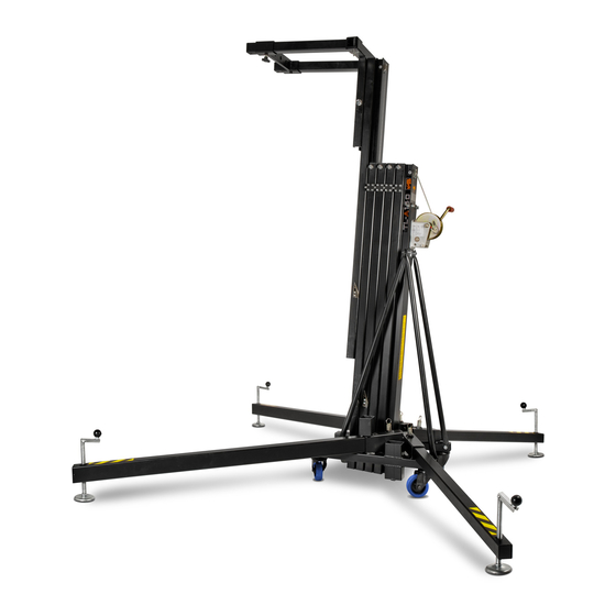
  • Seite 19 Bedienungsanleitung DEUTSCH 2.3 - Zulässige Hubkraft: 150 kg (331 lb) INHALTSVERZEICHNIS 2.4 - Mindesthublast : 25 Kg. 1. Einführung. 2.5 - Zulässige Hubhöhe: 5.3 m (17.4’) 2. Technische Daten. 2.6 - Mindesthöhe: 1.54 m (5’) 3. Sicherheitsmaßnahmen. 2.7 - Gefaltete Dimensionen: 4.
  • Seite 20 Bedienungsanleitung DEUTSCH 3. SICHERHEITSMAßNAHMEN. 3.1 - Der TL-A150 wurde konzipiert zum Heben und Senken von vertikalen Lasten. Nutzen Sie Ihn niemals zur Beförde- rung von Personen. 3.2 - Achten Sie darauf, das der TL-A150 Tower auf festem, geraden Untergrund steht. Und vergewissern Sie sich mit Hilfe der Wasserwaage (F), dass er eine vertikale Position zum Boden eingenommen hat.Bei Bedarf mittels des Stelltellers (Q) durch Drehen der Spindelkurbel (H) die entsprechende...
  • Seite 21 Bedienungsanleitung DEUTSCH 3.6 - Es ist nicht gestattet den Lift auf einem Fahrzeug mit einen mobilen Unterbau zu installieren! 3.7 - Bei Freiluftanwendungen den Turm auf festen Boden stellen und mittels Seilanker gegen Windbelastung sichern. Niemals an Fahrzeugen die Abspannungen befestigen oder an Gegenständen, die ausweichen könnten.
  • Seite 22 Bedienungsanleitung DEUTSCH 3.12 - Vor Gebrauch Seilzustand kontrollieren. Das Seil darf keine Seilbrüche oder Quetschungen aufweisen. Es dürfen auf keinem Fall Seile in einem schlechten Zustand verwendet werden. 3.13 - Alle Angebauten Teile sind für den Transport einzu- fahren. 3.14- Ölen oder Fetten der Fallbremsen ist zu unterlassen, da diese mit einem Druck und Hitzebeständigen Material bearbeitet wurden.
  • Seite 23 Bedienungsanleitung DEUTSCH 4. Bedienungsanleitung. Diagram 4.6.1 4.1 - Den Hebeturm auf den Transportrollen ( T ) abgestützt auf eine ebene und feste Fläche an der Arbeitsstelle aufstellen. 4.2 - Die Ausleger (P) aus der Transpor- halterung (S) herausnehmen und in deren Arbeitsaufnahmen (V) voll einschieben.
  • Seite 24 Bedienungsanleitung DEUTSCH Geschwindigkeit zu bedienen, um die Last Schlitten in seiner Parkposition wieder zu anzuheben oder abzusenken. verriegeln ( B ). Die Ausleger entsperren und Ab einem bestimmten Punkt wird sich diese in ihre Transportstellung ( S ) bringen. jeder Tower in einer anderen Höhe als der Die Befestigungsschraube anziehen.
  • Seite 25: Für Eine Kontinuierliche Betriebssicherheit Sind Ausschließlich Original

    5.5 - Für die Bestellung von Ersatzteilen ist stets dessen Bestellnummer anzugeben, welche den Stücklisten-Blättern dieser Anleitung zu entnehmen ist. VMB Service Deutschland: Tel : 04442 - 92900 Fax: 04442 - 929090 6. Garantie. Ab Kaufdatum und innerhalb der Garantie- zeit beim Händler beseitigt die PRO LIFTS...
  • Seite 26 TL-A150 SPARE PARTS SKETCHES / CROQUIS DE LAS PIEZAS DE REPUESTO DE TL-A150 Profiles / Barras.....................28 TL-A150 Profiles / Barras TL-A150 SRS System / Sistema retentor SRS Cable fixation / Prisionero cable Base profile lower area / Zona inferior perfil Base Profile upper area / Zona superior barras Alluminium stop piece / Pieza de aluminio tope barras Base / Base....................30...
  • Seite 27 TL-A150 1520C 1511 1512 1513 1514 7040 1515 7209 7209D 2026 PRO LIFTS S.L. Depósito legal y copyright 2014. Todos los derechos reservados.
  • Seite 28 TL-A150 1511 1512 1513 1514 1515 5414 1511 1512 1513 1514 1515 5414 PRO LIFTS S.L. Depósito legal y copyright 2014. Todos los derechos reservados.
  • Seite 29 TL-A150 3 mm 3 mm Profile 1514 6 mm Profile 1513 Profile 1512 Profile 1511 (TL-A150) (TL-A150) (TL-A150) (TL-A150) 3 mm 3 mm 3 mm 3 mm 3 mm 3 mm 3 mm 3 mm 6 mm 6 mm 6 mm 6 mm 1531 1532...
  • Seite 30 TL-A150 2140 2047 7962 1508 5429 6409 2044 7061 (x2) 2037 2026 PAT-02 7209 7209D MR-PAS (x2) (x2) 7078 2141 2152 (x2) PRO LIFTS S.L. Depósito legal y copyright 2014. Todos los derechos reservados.
  • Seite 31 TL-A150 1507N 7061 7061 7240 7160-AC 2044 7246 2152 7078 7246 2152 7078 2044 7061 7061 7240 7040 5401 PRO LIFTS S.L. Depósito legal y copyright 2014. Todos los derechos reservados.
  • Seite 32 TL-A150 5414 5430N 7242 7242 7243 3250 M14x150 7244 7245 7247 M14x180 5421 7223N 7246 7061F 7061F 7222N 7248 2044 7246 5415 5420 2047 5478 2050 (x2) 7222N 7061F 7061F 7061F 7061F 7222N 7223 7223 5419 Solo en tramos intermedios 7246 7246 NO EN CARRO 5414...
  • Seite 33 TL-A150 1502 1503 1504 1505 2029 2050 2051 2161 2046 Stabilizer kit 2037 TL-A150 Ref: 7039 2047 7048 2030 2048 2049 PRO LIFTS S.L. Depósito legal y copyright 2014. Todos los derechos reservados.
  • Seite 34 SPARE PARTS LIST / LISTA DE REPUESTOS TL-A150 Code Description GB / USA Descripción ES 1502 (B) Complete long leg (B Black) Pata larga completa (B Negro) 1503 (B) Long leg profile (50x70x1465mm) (B Black) Perfil pata larga (50x70x1465mm) (B Negro) 1504 (B) Complete short leg (B Black) Pata corta completa (B Negro)
  • Seite 35 Code Description GB / USA Descripción ES 2244 M6 Auto-block nut Tuerca autoblocante M6 3233 Conic screw M6x16 Tornillo cabeza cónica M6x16 3250 M8x20 Conic screw Tornillo cabeza cónica M8x20 3251 M6x16 Allen screw Tornillo allen M6x16 3252 SRS screwed plate Pletina roscada Retentor 3253 M6x10 Headless allen bolt...
  • Seite 36 Code Description GB / USA Descripción ES 7223N Black nylon roller Rodillo nylon negro 7234 M8x16 Screw Tornillo M8x16 7240 M10x35 Allen screw Tornillo allen M10x35 7242 M14 Washer Arandela M14 7243 M14 Auto-block nut Tuerca autoblocante M14 7244A Inertial brake lock (Ø21mm disk) Varilla freno de inercia (Disco Ø21mm) 7245 Brake lock support...
  • Seite 37 PRO LIFTS S.L. Depósito legal y copyright 2014. Todos los derechos reservados.
  • Seite 40 facebook / vmblifts Canal VMBLifts For further information follow the advise of our technicians: Para más información consulte con nuestros técnicos en: PRO LIFTS S.L. C/ Ciudad de Barcelona Nº19 Pol. Ind. Fuente del Jarro 46988 Paterna (Valencia) Spain Tlf Export: +34 96 171 81 86 Tlf Nacional: 96 171 81 83 email: info@prolifts.es web: www.prolifts.es...