Grundig R 23 DPL Serviceanleitung
Inhaltsverzeichnis
Service Manual
Grundig Service
Hotline Deutschland...
...Mo.-Fr. 8.00-16.30 Uhr
Technik:
TV/SAT
0180/52318-41
VCR/LiveCam
0180/52318-42
HiFi/Audio
0180/52318-43
Car Audio
0180/52318-44
Telekommunikation
0180/52318-45
Fax:
0180/52318-51
Ersatzteil-Bestellannahme:
0180/52318-40
Telefon:
0180/52318-50
Fax:
DOLBY SURROUND
P R O
L O G I C
POWER
A• •B
LOUDNESS
SURROUND
SPEAKERS
Zusätzlich erforderliche
Unterlagen für den Komplettservice
Additionally required
Service Manuals for the Complete Service
Service
Service
Manual
Manual
Sicherheit
R 23 DPL
Safety
Sach-Nr./Part No.
Sach-Nr./Part No.
72010-757.20
72010-800.00
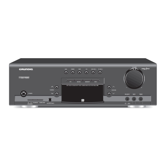
AUX
TUNER
TAPE
CD
PTY
MONO
MEMORY
HIFI HIGH SENSITIVITY RDS SURROUND RECEIVER R23 DPL
TUNING
R D S
HEADPHONES
VOLUME
VCR/VID.1
TV/VID.2
INFO
STATION
BALANCE
BASS
LEFT
RIGHT
–
HiFi
R 23 DPL
TREBLE
+
–
+
Btx * 32700 #
Sachnummer
Part Number 72010-757.20
Änderungen vorbehalten
Subject to alteration
Printed in Germany
VK231 0198
Inhaltsverzeichnis

Verwandte Anleitungen für Grundig R 23 DPL


Inhaltszusammenfassung für Grundig R 23 DPL
- Seite 1 Service Manual HiFi R 23 DPL Grundig Service Hotline Deutschland..Mo.-Fr. 8.00-16.30 Uhr Technik: TV/SAT 0180/52318-41 VCR/LiveCam 0180/52318-42 HiFi/Audio 0180/52318-43 Car Audio 0180/52318-44 Telekommunikation 0180/52318-45 Fax: 0180/52318-51 Ersatzteil-Bestellannahme: 0180/52318-40 Telefon: 0180/52318-50 Fax: VOLUME TUNER TAPE VCR/VID.1 TV/VID.2 DOLBY SURROUND P R O...
-
Seite 2: Inhaltsverzeichnis
Isolating Transformer, Test Generator, Stereo Coder, Oscilloscope, NF-Voltmeter, Klirrfaktormeßgerät. Digital Voltmeter, AF-Voltmeter, Distortion Meter. Beachten Sie bitte das GRUNDIG Meßtechnik-Programm, das Sie Please note the Grundig Catalog “Test and Measuring Equipment” unter folgender Adresse erhalten: obtainable from: GRUNDIG Instruments GRUNDIG Instruments Test- und Meßsysteme GmbH... -
Seite 3: Technische Daten
R 23 DPL Allgemeiner Teil / General Section Technische Daten Technical Data Verstärker Amplifier part Ausgangsleistung (acc. DIN 45500) Output power (acc. DIN 45500) Musikleistung 4Ohm ............2 x 150W Music 4Ohm ............... 2 x 150W Sinusleistung 4Ohm ............2 x 100W Nominal 4Ohm .............. -
Seite 4: Bedienhinweise
Geräte eingeschaltet sind. Sender-Frequenz um. Buchsen CD an. Videorecorders an die Buchse VCR/- LOUDNESS Mit diesem Schalter können Sie die :Sie hören nacheinander immer RECEIVER R 23 DPL TEST TAPE Verbinden Sie die LINE IN-Buchsen VID1 OUT an. Schließen Sie den STATION... - Seite 5 (RDS), RADIOTEXT, RDS time and tone from your speakers in the Connect your CD player to the CD channel output socket of your video RECEIVER R 23 DPL adapt the volume level to individual station frequency. following sequence: Front left sockets.
- Seite 6 ADAPTING THE SURROUND MODE VALUES RADIO TUNING TO RADIO STATIONS Automatic tuning Adapting the Surround mode values • Press the SURROUND button again. RDS Radio Data System > 1.5 SEC – You will now hear a test tone from the left, •...
-
Seite 7: Ausbauhinweise
R 23 DPL Allgemeiner Teil / General Section Ausbauhinweise Disassembly Instructions Gehäuseabdeckung abnehmen Removing the Cabinet Top - 10 Gehäuseschrauben A herausdrehen und Abdeckung abneh- - Undo 10 screws A and remove the cover (Fig. 1). men (Fig. 1). Fig. 1 Fig. - Seite 8 Allgemeiner Teil / General Section R 23 DPL Fig. 8 4. Hauptplatte ausbauen 4. Removing the Main Board - Tuner-Platte und Lautstärke-Platte ausbauen (Punkt 2 und 3). - Remove the Tuner Board and Volume Board (point 2 and 3). - 22 Schrauben I und 2 Schrauben N auf der Geräterückseite - Undo 22 screws I and 2 screws N on the rear of the set (Fig.
- Seite 9 R 23 DPL Allgemeiner Teil / General Section 6. Frontblende ausbauen 6. Removing the Front Cover - Lautstärke-Platte ausbauen (Punkt 3). - Remove the Volume Board (point 3). - Je 2 Schrauben O (Fig. 12) links und rechts der Frontblende - Undo 2 screws O each (Fig.
-
Seite 10: Abgleichvorschriften
Abgleichvorschriften / Adjustment Procedures R 23 DPL Abgleichvorschriften Meßgeräte: Meßsender, Stereocoder, Oszilloskop, Digitalvoltmeter, NF-Voltmeter, Klirrfaktormeßgerät Hinweis: Das Frontend ist ein komplett abgeglichener Baustein. Die Abstimmspannungen des Frontends haben folgende Größen: 87,5MHz = typ. 1,6V min. 1,3V 108MHz = typ. 8,3V max. 9,5V... -
Seite 11: Adjustment Procedures
R 23 DPL Abgleichvorschriften / Adjustment Procedures © Adjustment Procedures Test Equipment: Test Generator, Stereo Coder, Oscilloscope, Digital Voltmeter, AF-Voltmeter, Distortion Meter Note: The frontend is a completely preadjusted module. The values of the tuning voltages are: 87.5MHz = typ. 1.6V min. 1.3V 108MHz = typ. - Seite 13 R 23 DPL Platinenabbildungen und Schaltpläne / Layout of PCBs and Circuit Diagrams R 23 DPL Platinenabbildungen und Schaltpläne / Layout of PCBs and Circuit Diagrams Verdrahtungsplan / Wiring Diagram GRUNDIG Service 3 - 2 GRUNDIG Service 3 - 3...
- Seite 14 Platinenabbildungen und Schaltpläne / Layout of PCBs and Circuit Diagrams R 23 DPL Platinenabbildungen und Schaltpläne / Layout of PCBs and Circuit Diagrams R 23 DPL Schaltplan / Circuit Diagram: -Netzteilplatte / Supply Board -Netztrafo / Power Transformer PAGE 3-8...
-
Seite 15: Power-Led-Platte
R 23 DPL Platinenabbildungen und Schaltpläne / Layout of PCBs and Circuit Diagrams R 23 DPL Platinenabbildungen und Schaltpläne / Layout of PCBs and Circuit Diagrams Platinenabbildungen / Layout of PCBs Netzteilplatte / Supply Board Bestückungsseite / Component side Lautstärkeplatte / Volume Board... - Seite 16 Platinenabbildungen und Schaltpläne / Layout of PCBs and Circuit Diagrams R 23 DPL Platinenabbildungen und Schaltpläne / Layout of PCBs and Circuit Diagrams R 23 DPL Schaltplan / Circuit Diagram: -Hauptplatte / Main Board PAGE 3-13 PAGE 3-12 PAGE 3-5...
- Seite 17 R 23 DPL Platinenabbildungen und Schaltpläne / Layout of PCBs and Circuit Diagrams R 23 DPL Platinenabbildungen und Schaltpläne / Layout of PCBs and Circuit Diagrams Platinenabbildung / Layout of PCB VON OBEN Bestückungsseite / Component side TOP VIEW 2SB1570...
- Seite 18 Platinenabbildungen und Schaltpläne / Layout of PCBs and Circuit Diagrams R 23 DPL Platinenabbildungen und Schaltpläne / Layout of PCBs and Circuit Diagrams R 23 DPL Schaltplan / Circuit Diagram: -Tuner-Platte / Tuner Board -Kopfhörerplatte / Headphone Board -Klangreglerplatte / Tone Board -Lautstärkeregler-LED-Platte / VR LED Board...
-
Seite 19: Surround Board
R 23 DPL Platinenabbildungen und Schaltpläne / Layout of PCBs and Circuit Diagrams R 23 DPL Platinenabbildungen und Schaltpläne / Layout of PCBs and Circuit Diagrams Platinenabbildungen / Layout of PCBs Bestückungsseite / Component side Klangreglerplatte Surround-Platte Tone Board Surround Board Tunerplatte / Tuner Board Kopfhörerplatte... - Seite 20 Platinenabbildungen und Schaltpläne / Layout of PCBs and Circuit Diagrams R 23 DPL Platinenabbildungen und Schaltpläne / Layout of PCBs and Circuit Diagrams R 23 DPL Schaltplan / Circuit Diagram IC602 LA1851N FM Front-End (Tuner-Platte Seite 3-12 / Tuner Board Page 3-12)
-
Seite 21: Exploded View
Explosionszeichnung Exploded View R 23 DPL... -
Seite 22: Ersatzteilliste Spare Parts List
IC 705 75954-503.98 IC BA6208 D 613 8309-215-045 DIODE 1N4148 IC 801 19799-252.97 IC 4052 (C-MOS) 75710-310.51 R 23 DPL SCHWARZ R 23 DPL BLACK D 614 8309-215-045 DIODE 1N4148 IC 802 75986-200.77 IC NJM 4558 DD 0001.000 75954-503.85 KNOPF VOLUME... - Seite 23 POS. NR. SACHNUMMER BEZEICHNUNG POS. NR. SACHNUMMER BEZEICHNUNG POS. NO. PART NUMBER DESCRIPTION POS. NO. PART NUMBER DESCRIPTION Q 323 75954-503.21 TRANSISTOR KTC3198GR R 919 8705-227-025 MOW 0411 10 OHM 5% Q 324 75950-016.09 TRANS.KTA 1266 Y R 926 75954-504.73 MOW 0,47 OHM 5W 5% Q 325 75954-503.21...
- Seite 24 90471 Nürnberg 09 11/7 03-0 Marketing und Vertrieb Europa GmbH Kundendienst Europa GRUNDIG BELUX N.V. GRUNDIG NORGE A. S. Deltapark Unit 3, Weihoek 3 Glynitveien 25, Postboks 234 B-1930 Zaventem N-1401 00 32-2-7 16 04 00 00 47-64 87 82 00 GRUNDIG OY GRUNDIG INTERNATIONAL LTD.