Philips PM8041 Gebrauchsanleitung

Verwandte Anleitungen für Philips PM8041


Inhaltszusammenfassung für Philips PM8041
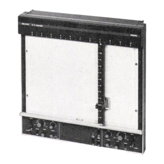
- Seite 1 PHILIPS Standard A4 X-Y Recorder PM 8041 MultipurposeA4 X-Y Recorder PM8141 Multipurpose A3 X-Y Recorder PM8131 770401 9499 03511 PHILIPS...
- Seite 2 PHILIPS ST 2033 OPERATION MANUAL GEBRAUCHSANLEITUNG MODE D'EMPLOI A4 X-Y Recorder PM8041 Standard A4 x-Y Recorder PM8141 Multipurpose A3 X-Y Recorder PM8131 Multipurpose PHILIPS 770401 9499 03511...
-
Seite 3: Inhaltsverzeichnis
Principle of operation Arbei tswei se Principe de fonctionnement Technical specification Technical specification Technical specification Time—base unit PM 9884 Zeitbasis—Einheit PM 9884 Unite de base de temps PM 9884 N.V. PHILIPS' GLOEILAMPENFABRIEKEN - EINDHOVEN - THE NETHERLANDS - 1977. PRINTEDIN THENETHERLANDS... -
Seite 4: Introduction
INTRODUCTION The Philips recorders PM 8041, PM 8131 and PM 8141 are multirange X—Y recorders, suitable for a wide variety of applicationswherethe relationshipof two variablesy = f (x) hasto be recorded. The STANDARD A4 version PM 8041 is a low—cost recorder for routine applications with a multirange unit with calibrated sensitivities from 2 rn\//cm to I V/ cm;... -
Seite 5: Optional Accessories
ACCESSORIES 2.1. Supplied with the instrument (Fig. I, page26) Operation manual Dust cover — A4 roll chart of 15m recordinglength PM9940or I bookof graphpaper Service box comprising: • spare fuse • measuring potentiometer • I brush •• silk cloth for cleaning measuring potentiometer •... -
Seite 6: Temperature Measurements
It can be ordered from the Superintendent of Documents U.S. Government Printing Office, Washington D.C. 20402. Ordering reference : SD Cataloque No. 13.44.125. Stocknumber 0303 — 01177. For more information about thermocouples (THERMOCOAX) apply to your local Philips organisation for data on THERMOCOAX. -
Seite 7: Current Measurements
4. If thermocouplewires are too short, extensionby compensationcable is possible. When using compensation cable take care that the wires of same polarities are interconnected. 3.5. Current measurements A current can be measured and recorded by converting the current into a voltage, which corresponds to one of the mV ranges of the recorder. -
Seite 8: Zero Adjustment
OPERATION Power switch ON - OFF 5.1. Before the recorder is switched on ensure that the "PENII switch is in the "UP" position and the ZERO—RECORDswitch of both X and Y are in the ZERO position. The mains voltage is switched "ON It and "OFF" by meansof the "POWER" switch. When switched "ONI' the pilot lamps serves as an indication that power is connected. - Seite 9 MAINTENANCE The maintenance requirements of the recorder have been reduced to a minimum. It is recommended that the operationsdescribedbelow be performedonce every six months. If the recorderis used underparticularly unfavourable circumstances, t his interval shouldbe shorter. 6.1. Measuring potentiometers A dirty measuring potentiometer c an give an irregularand iumpyregistrationespeciallywith slowly changing input signals.
- Seite 10 PRINCIPLE OPERATION The recorders are based on the principle of automatic compensation. The measuring system comprises two servo—systems one for X and one for Y deflection. The block diagram is given in Fig. 8 , page40 . The main units are: Input unit, 2.
- Seite 11 TECHNICAL SPECIFICATION PM 8141 PM 8131 PM 8041 25% of f.s.d. at reference temperature 23 C Max. error ACCURACY SPAN of f. s. d. max. DEAD BAND 0.5 pV/OC max. 20pV/OC max. TEMPERATURE DRIFT 75 cm/s (Y) WRITING SPEED 60 cm/s (X) cm/s (Y) 3800 cm/s 3900...
- Seite 12 10. TIME - BASE UNIT (Fig. 7, page 36) 10.1. Introduction The time—base unit PM 9884 is an optional plug—in unit for both PM 8041, PM 8141 and PM 8131 provides an output voltage which increases linearity with time. The recorder then can be used as an X—t or recorder.
-
Seite 13: Adjustment
The amplification of an operational amplifier is very high, and can be considered as infinite. The input voltage of the amplifier can thus be taken as zero. When the start switch is depressed, a capacitor C103 is charged with a constant current via resistor R108. -
Seite 14: Einleitung
EINLEITUNG Die Philips Recorder PM 8041, PM 8131 und PM 8141 Mehrbereichs X—Y Schreiber, geeignet fur eine Fulle von Anwendungen,wobei die Beziehungzweier veränderlicher Grösseny = f (x) registriert werden soll . Die STANDARD A4 Ausftjhrung PM 8041 ist ein kostenfreundlicher Schreiber ftjr routinemässige Anwendungen, er verfUgt Über eine Mehrfachbereichseinheit... -
Seite 15: 2. Zubehör
2. ZUBEHÖR 2.1. Mit dem Gerät geliefert (Fig. 1, Seite 26) Bedienungsanleitung — Staubschutzhaube — A4—Papierrol le, 15 m Aufzeichnungslänge PM 9940 Oder — I Buch Millimeterpapier. — Servicekasten enthaltend: • Ersatzsicherungen • Öl FürdasMesspotentiometer • I Pinsel • Seidentuch zum Reinigen des Messpotentiometers •... -
Seite 16: Erdung Der Eingangsschaltung
FUr ein 60 Hz Netz mussder entsprechende Schalter im Filter auf 60 Hz Stand Bemerkung: (fur X und Y Achsen) gestellt werden (Abb. 3a, b, c, Seite 26). Der Schalter ist zugånglich, wenn die Abdeckplatte des Papierrollenbehälters durch Lösen der beiden Schrauben abgenommen wird. 3.2. - Seite 17 Für nähere Einzelheiten Über Thermoelemente fordem Sie bitte "Thermocoaxtl Daten bei Ihrer örtlichen Philips Organisation an. Falls Thermoelmentdråhte z u kurz Sind, könnenSiemit Hilfe von Ausgleichsleitungenverlängert werden. Bei Anwendung von Ausgleichsleitungen ist darauf zu achten, dassdie gleichen Polaritdten miteinander verbunden werden.
-
Seite 18: Bedienung
4.3. Gestelleinbau Das Gehöuse des Schreibers ist derart konstruiert, das fur Einbau in ein 19'I Gestell keine Befestigungsträger erforderlich Sind. Beim Schreiber PM 8131 werden die Schraublöcher nach Abnahme der beiden schmalen grauen Leisten (an ieden Seite eine) zugänglich; bei den A4—Format Model len müssen die linke Leiste und die beide Eingangsmoduln entfernt werden. -
Seite 19: Reinigen Der Aussenflächen
Eine Reihe einfacher Fehler können anhand nachstehender Liste selbst behoben werden. 1m Falle ernster Schwierigkeiten wenden Sie sich bitte an die nächstgelegene PHILIPS SERVICE ORGAN ISA TION. MÖGLICHE URSACHE FEHLER Gerdt funktioniert nicht —Defekte Sicherung Oder keine Netzspannung Lampe POWER ON leuchtet nicht. - Seite 20 ARBEITSWEISE Die Schreiber arbeiten nach der automatischen Kompensationsmethode . DasMess—System enthålt zwei identische Servosysteme f ur X und Y—Ablenkung. Das Blockschaltbild ist Abb. 8 Seite 40 zu entnehmen. Essind Folgende Haupteinheiten zu unterscheiden: Eingangseinheit Servoverstä&er 3. Schreibfederbedienungs —Einheit Erlöuterung des Blockschaltbi Ids DasEingangssignal U x WirdÜberBereichsabschwächer I und BrummfilterdemVorverstårker zugefUhrt.DerVerstdrkungsgrad desVorverstårkers i st mit Hilfe desBereichsabschwächer II regelbar.
- Seite 21 TECHNICAL SPECIFICATION PM 8041 PM 8141 PM 8131 Max. error ± 0. of f.s. d. at reference temperature 23 C ACCURACY SPAN O. 10/0of f.s.d. DEAD BAND 20p\//OC max. 0.5pV/OCmax. TEMPERATURE DRIFT 75 cm/s (Y) WRITING SPEED 60 cm/s (X) 3800 cm/s 3900 cm/s (Y) ACCELERATION...
-
Seite 22: Zeitbasis-Einheit
10. ZEITBASIS-EINHEIT PM 9884 (Abb. 7, Seite 36) 10.1. Einleitung Die Zei tbasis—Einheit PM 9884 ist ein Einsteckeinheit fur die Schreiber PM 8041 , PM 8131 PM 8141, Sie liefert eine zeitlinear ansteigende Ausgangsspannung. Die Schrei ber können dann als Oder Schreiber verwendet werden. -
Seite 23: Offset-Einstellen
Die Ausgangsspannung Wird dem Eingang eines Endverstärkerszugeftjrt (Punkt A). Beschreibung des Blockschaltbildes (Abb. 8 , Seite 40). Die Verstarkung eines Operationsverstärkers ist sehr grossund kann als unbegrenzt angenommen weden. Die Eingangsspannung des Verstörkers ist dann als Nul I anzunehmen. Wenn Schalter STARTeingedrückt ist, Wird Kondensator C 103 Über Widerstand R108 mit einem Konstantstrom aufgeladen. - Seite 24 INTRODUCTION Les enregistreurs Philips PM 8041, PM 8131 et PM 8141 sont des enregistreurs X —Y gammes multiples et sont utiles pour enregistrer le rapport entre deux variables y = f (x), ce qui constitue une gammeétenduedtapplications. La version standard A4 PM 8041 est d'un coot peu élevé; il est d lun aide précieuse dans les applicationsde routineet Offre9 gammes c alibréesde 2 mV/cmb I V/cm, le réglagevariable...
-
Seite 25: Accessoires
ACCESSOIRES 2.1. Compris la livraison (Fig. 1, — Mode d lemploi — HOUsse de protection Rouleaude papier de 15 m PM9940 ou I paquet de papier graphique Bone de service comprenant: • fusibles de réserve • huile pour le de mesure •... -
Seite 26: Mesures De Température
3.2. Mise a la terre du circuit d'entrée CONTROL La source de tension ou capteur doit etre connecté I •enregistreur de préférence I'aide d'un cordon blindé deux conducteurs; des cables non—blindés peuvent entratner des signaux diinterférence pouvant affecter les résultats de la mesure. La mise la terre de la source de tension ou capteur peut se faire de différentes L'expérience apprendra laquelle des... -
Seite 27: Mesures De Courant
Pour plus nformations sur les thermocouples (THERMOCOAX), consulter 'organisation Philips locale. Si fils de thermocouple sont trop courts, un cable de compensationpeut etre utilisé. Dans ce cas, veiller ce que les fils de polarité identiques soient interconnectés. 3.5. Mesures de courant... -
Seite 28: Mise En Service
MISE EN SERVICE 5.1. Commutateur ON-OFF Avant de mettre Ilappareil en service, slassurerque le commutateur "PEN" est en position et le commutateur "ZERO—RECORD" en position "Z EROI'. La tension secteur est enclenchée et déclenchée b I laide du commutateur ON—OFF. LorsqueI •enregistreur est enclenché, la lampe témoin est allumée. -
Seite 29: Entretien
DEPANNAGE Encas de pannesimples, I lutilisateur peut consulter la liste ci-ap&s. Cependant, si des probl&nes plus sérieux apparaissent, il est bon de contacter Ilorganisation de service Philips la plus proche. PANNE CAUSE POSSIBLE Llappareil ne fonctionne pas et ia —fusible... -
Seite 30: Principe De Fonctionnement
PRINCIPE DE FONCTIONNEMENT Lesdeux enregistreurssont baséssur le principe de la compensation automatique. Le systhle de mesurecomprenddeux servomécanismes pourdéflexions X et Y. Le schémasynoptiqueest illustré la figure 8, page40. Lesunités principales sont décrites dans la description du schémasynoptique, et ce dansI 'ordre suivant: Unité... - Seite 31 TECHNICAL SPECIFICATION PM 8141 PM 8041 PM 8131 Max. error ± 0.25% of f.s.d. at reference temperature 23 C ACCURACY SPAN 0.1% of f.s.d. max. DEAD BAND 20pV/OC max. 0.5 pV/OC max. TEMPERATURE DRIFT 75 cm/s (Y) WRITING SPEED 60 cm/s (X) 3800 cm/s 3900 cm/s (Y) ACCELERATION...
- Seite 32 UNITE DE BASE DE TEMPS PM 9884 (Fig. 7) 10.1. Introduction Llunité de basede temps PM 9884 est une unité enfichable pour enregistreurs PM 8041, PM 8131 et PM 8141; elle produit une tension de sortie croissant linéairement avec le temps. Lesenregistreurs peuvent étre uti lisés alors en tant qulenregistreurs ou Y—t.
-
Seite 33: Principe De Fonctionnement
Principe de fonctionnement (Fig. 8, page 40) 10.4. La base de temps PM 9884 consiste principalement en un amplificateur opérationnel raccordé comme un intégrateur. Entre la tension dientrée Ui et la tension de sortie Uo existe liéquation suivante: sui vante: La tension de sortie est appliquée I'entrée de I'amplificateur de puissance (point A). -
Seite 34: Caractéristiques Techniques
Caractéristiques techniques 10.6. 0,5- 1-2-5- 10 sec/cm Taux de balayage 3% pleine déviation dléchelle Précision ± O,596 pleine déviation dléchelle Linéarité ± V pour axe X (position zéro 0%) Tension de sortie ± 4,65 V pour axe Y (position zéro 0%) Résistance diisolement Automatique, vets le basau démarrageet vers le haut... -
Seite 35: Time Base Unit Pm9884
U ZERO A202 R229 REF. A 202 VOLTAGE DAMPING FUNCTIONAL DIAGRAM PM8041 PM8141 PM8131 -MEASURING POTENTIOMETER ZERO SUPPRES- SION SWITCH ZERO GAIN ATTENUATOR AMPLIFIER ZERO POWER AMPLIFIER v 207 INPUT TIME BASE OFFSET ATTENUATOR V208 LIMIT CIRCUIT TO GROUND TERMINAL... -
Seite 36: Pm 9884
FILTER 0200 SUMING AMPLIFIER .'scn. 1203 '20s VOLTAGE s: aero "02-12 CHART cowac_ HOLD 1001 EXTERNAL LIMIT CONTROL CONNECTOR CONTROL UNIT oyc. r20'— '2•03_' W AXIS PEN LIFTI SOLENOID MAINS POWER X -AXS nt3_• nous Fig. Complete c ircuitdiagram PM8041. - Seite 37 r¯MULTlRANGE U NIT X N2 SERVO x_AXlS AMPLIFIER TIME BASE UNIT PM9884 INPUT FILTER PRE_ AMPLIFIER RANGE SELECTOR XIO' S20' ATTENUATOR "02-0 BE CORO 921' POWER SUPPLY SO v OUTPUT z SC '309 INPUT so—wc. OFFSET 5082 R'25 PHOTO 0mO'C" COUPLER START vtOj...
- Seite 38 UNIT N2 SERVO AMPLIFIER X AXIS pM8141 xaoz AMPLIFIER * R236 RZ 37 R202 s 201 POWER SUPPLY v2d' x703 R232 CHOPPER OSCILLATOR R235 INPUT FILTER A203 8 4203 12 S203 ONE'9 020' R233 C 773 C22S 0203 PDC•C 1C PO'COIC R2'0 •.cop...
- Seite 39 MULTIRANGE UNIT v 203 N2 SERVO AMPLIFIER X AXIS pM8141 AMPLIFIER RECORO Rao' POWER v20' asci"' A2J2 CHOPPER OSCILLATOR INPUT FILTER A 203 5203 DNA'S 0220 POWO'C 0203 wz06' INPUT R23S CHOPPER DRIVE R20S R2.2 R738 0202 020' C207 2SA79• t 202 c 212 mv'Cm...
- Seite 40 ANGE UNIT N2 SERVO AMPLIFIER X-AXIS pM8131 S2Ct AMPLIFIER R236 R202 POWER SUPPLY CHOPPER OSCILLATOR R232 J2C2g u20J INPUT FILTER 02C' QIAOJ. Q 23 22 3 D 203 POLOCIC w 7•.62 CHOPPER DRIVE 10 u S202 35 v Rzos TO TRANSFORMER t102-B R2ub T 102...
- Seite 41 MULTIRANGE UNIT N2 SERVO AMPLIFIER FOR X-AXIS PM8131 S2Ct AMPLIFIER RECORO POWER CHOPPER OSCILLATOR INPUT FILTER 22 i INPUT CHOPPER DRIVE 02 grrr, c22' D 702 020' v 216 mvkm R 221 •272 SCH. .262 Y2A707 R2'2 ZERO OFFSET CIRCUIT .zss OVERLOAD PROTECTION...
- Seite 42 Office; Singapore 12; tel. 538811 tel. 02/13.76.00 Jakarta; tel. 51985-51986 South Africa : South African Philips (Pty) Bolivia: Industrias BolivianasPhilips S.A. Iran : Philips Iran Ltd., P.O.B. 1297. Teheran; Ltd.. P.O.B. 7703. 2. Herb Street, Doorn- LA Jon postal 2964 La Paz tel. 50029 tel.