Werbung
Quicklinks
Werbung

Verwandte Anleitungen für HEIDENHAIN EXE 900


Inhaltszusammenfassung für HEIDENHAIN EXE 900
- Seite 1 ˜ ˜ Betriebsanleitung Operating Instructions ˜ ˜ 2/2003...
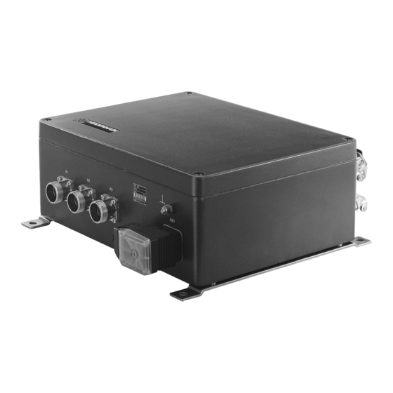
- Seite 2 Technical Description/Items Supplied/Options Die EXE 900 ist eine Interpolations- und Digitalisierungs-Elek- The EXE 900 is an interpolation and digitizing electronics unit in tronik in einem robusten Gussgehäuse. Sie eignet sich zum a sturdy cast-metal housing. It is suited for use with Anschluss an HEIDENHAIN-Längen- und Winkelmessgeräte...
- Seite 3 Contents Seite Page 2 Beschreibung 2 Description 2 Lieferumfang und Optionen 2 Items Supplied and Options 4 EXE 900 – Übersicht 4 EXE 900 – Overview 6 Mechanischer Anbau 6 Mounting 8 Elektrischer Anschluss 8 Electrical Connection 9 Kabelübersicht 9 Cable Overview...
- Seite 4 EXE 900 – Übersicht EXE 900 – Overview Eingänge EXE 900 Interpolation Takt- Eingangs- Min. Flanken- Ausgänge frequenz f frequenz f abstand a pro Eingang EXE 900 Inputs Interpolation Clock Input Min. edge Outputs frequency f frequency f separation a...
- Seite 5 EXE 900 – Übersicht EXE 900 – Overview Eingänge EXE 900 Interpolation Takt- Eingangs- Min. Flanken- Ausgänge frequenz f frequenz f abstand a pro Eingang Inputs EXE 900 Interpolation Clock Input Min. edge Outputs frequency f frequency f separation a...
- Seite 6 Mechanischer Anbau Mounting Den Anbauort richtig wählen Select the proper mounting location ‘ Abstand der EXE und der signalführenden Kabel zu Stör- ‘ Ensure that the EXE and its signal cables are located at the quellen einhalten: proper distances from sources of interference: •...
- Seite 7 Mechanischer Anbau – Hauptabmessungen Mounting – Overall Dimensions ˜ ˜ 117 .5 ˜ ˜ ‘ Die EXE mit vier Befestigungsschrauben M8 x 20 DIN 912 ‘ Mount the EXE with four mounting screws M8 x 20 montieren. ISO 4762.
- Seite 8 Die richtigen Kabel verwenden: Use the proper cable: ‘ Messgeräte und EXE nur mit HEIDENHAIN-Kabeln verbinden, um ‘ Connect the encoders to the EXE only with HEIDENHAIN die Qualität der Messgerät-Signale zu gewährleisten. cable to guarantee the quality of the encoder signals.
- Seite 9 Kabelübersicht Cable Overview max. 30 m * max. 30 m Option 237 280-01 309 774-xx 309 773-xx EXE 900 207 620-xx 100 ... 240 V 209 009-xx Option 284 477-01 max. 50 m ** 207 985-01 207 985-02 ˜ ÷ 120 mA ÷...
- Seite 10 Netzanschluss Connection to Power Supply Stromschlag-Gefahr! Danger of Electrical Shock! Vor Öffnen des Gerätes Netzstecker ziehen! Pull the power plug before opening the housing! Netzteil Power supply Spannungsbereich: 100 V bis 240 V ~ (–15 % bis +10 %), Voltage range: 100 V to 240 V AC (–15 % to +10 %), 48 Hz bis 62 Hz;...
- Seite 11 Netzanschluss Connection to Power Supply ‘ Netzleitung ‘ 7 mm an Klemmen 1 ‘ Power line dia. 7 mm at terminals 1 und 2. and 2. ‘ Schutzleiter an Klemme þ. ‘ Grounding conductor at terminal þ. ‘ Zug-Entlastung herstellen. ‘...
- Seite 12 Current consumption of the Messgeräte max. 700 mA connected encoders max. 700 mA ˜ 9-polige Flanschdose (Farbangaben gelten für HEIDENHAIN-Kabel) 9-pin Flange socket (colors specified as they apply to HEIDENHAIN cable) Schirm shield – – – grün gelb blau grau...
- Seite 13 Abtastkopf zum Maßstab justiert werden. Die Prüfung scanning head must be adjusted to the scale. The adjustment is der Justage erfolgt mit dem Adapter Nr. 19 von HEIDENHAIN checked with Adapter No. 19 from HEIDENHAIN (Id.-Nr. 110 257-ZZ) und einem Zweistrahl-Oszillographen.
- Seite 14 EXE-Eingangssignale EXE Input Signals +5 V (blau) EXE ohne/5/10fach: 0.95 bis 2.2 V EXE 25/50fach: 1.85 bis 4.2 V (90° el.) (blue) EXE none/5-/10-fold: 0.95 to 2.2 V EXE 25-/50-fold: 1.85 to 4.2 V +5 V (rot) EXE ohne/5/10fach: 0.95 bis 2.2 V EXE 25/50fach: 1.85 bis 4.2 V...
- Seite 15 EXE-Ausgangssignale TTL EXE Output Signals (TTL) Inkrementalsignale: Rechteckimpulsfolgen Incremental signals: Square-wave pulse mit 90 ° el. Phasenversatz, so- und U trains U and U with 90 el. phase shift, plus their inverted pulse trains ‡ and ˆ wie deren invertierte Impulsfolgen ‡ und ˆ...
- Seite 16 EXE-Ausgangssignale TTL EXE Output Signals (TTL) EXE ohne/5fach-/10fach-Interpolation EXE without/5-fold/10-fold interpolation Die Ausgangssignale werden kontinuierlich ausgegeben und The output signals are transmitted continuously and are path- sind – bezogen auf die Eingangssignale – wegproportional. Die proportional relative to the input signals. The signal transit time auftretende Signallaufzeit zwischen EXE-Ein- und Ausgang ist between the EXE input and output depends on the entered abhängig vom eingestellten Flankenabstand und liegt zwischen...
- Seite 17 EXE-Ausgangssignale TTL EXE Output Signals (TTL) Signalpegel Signal levels ø 2,5 V bei –I ÷ 20 mA ø 2.5 V at –I ÷ 20 mA High High High High ÷ 0,5 V bei –I ÷ 20 mA ÷ 0.5 V at –I ÷...
- Seite 18 25-polige Harting-Flanschdose für TTL-Ausgangssignale 25-pin Harting flange for TTL output signals (Farbangaben gelten für HEIDENHAIN-Kabel) (colors specified as they apply to HEIDENHAIN cable) Je nach EXE-Ausführung ist die Harting-Flanschdose wie folgt The assignment of the Harting flange socket is reflected in the...
- Seite 19 TTL-Ausgang: max. 50 m mit HEIDENHAIN-Kabel electronics [25 x 0,34] mm und empfohlener Eingangs- TTL output: Max. 50 m with HEIDENHAIN cable [25 x schaltung der Folge-Elektronik, 0.34] mm and recommended input circuitry max. 20 m bei minimalem Flankenabstand of subsequent electronics. Max. 20 m with a = 0,125 µs...
- Seite 20 EXE-Ausgangssignale – Optionen EXE Output Signals – Options Option: zusätzlicher TTL-Ausgang Option: Additional TTL Output (Adapterkabel mit Id.-Nr. 284 477-01) (Adapter cables Id. Nr. 284 477-01) ‘ Deckel der EXE abnehmen. ‘ Remove the EXE housing cover. ‘ Blende am Gehäuse entfernen. ‘...
- Seite 21 EXE-Ausgangssignale – Optionen EXE Output Signals – Options ˜ ˜ ˜...
- Seite 22 Einstellungen EXE 922, EXE 932 Settings for EXE 922, EXE 932 Auf der Platine befinden sich für jede Achse sechs Schalter. Bei There are six switches on the board for each axis. In the EXE den EXE-Ausführungen für zwei Achsen ist die nicht benötigte models for two axes, the other axis position is unoccupied.
- Seite 23 Einstellungen EXE 922, EXE 932 Settings for EXE 922, EXE 932 , ‡, U ˆ bei Š = low Referenzimpuls-Breite Schalter Schalter Ausgänge: U , ‡, U , ˆ at Š = low Reference pulse width Switches Switches Outputs: S1 / 7 / 13 S2 / 8 / 14 90 °...
- Seite 24 Einstellungen EXE 937 Settings EXE 937 Aufsteckplatine Plug-on PCB Die Einstellung der EXE 937 für die Achse X1 und X3 entspricht The settings of the EXE 937 for the axes X1 and X3 are the der Einstellung für die EXE 922 und EXE 932. same as for the EXE 922 and EXE 932.
- Seite 25 Einstellungen EXE 937 Settings EXE 937 , ‡, U , ˆ bei Š = low Referenzimpuls-Breite und Schalter Schalter Ausgänge: U Hysterese für Inkrementalsignale , ‡, U , ˆ at Š = low Reference pulse width and hysteresis for Switches Switches Outputs: incremental signals...
- Seite 26 Einstellungen EXE 914, EXE 924, EXE 934, EXE 935 Settings EXE 914, EXE 924, EXE 934, EXE 935 Auf der Platine befinden sich für jede Achse fünf Schalter. Bei There are five switches on the PCB for each axes. In the EXE den EXE-Ausführungen für eine oder zwei Achsen sind die nicht models for one or two axes, the other axis positions are benötigten Achsen auf der Platine nicht bestückt.
- Seite 27 Einstellungen EXE 914, EXE 924, EXE 934, EXE 935 Settings EXE 914, EXE 924, EXE 934, EXE 935 , ‡, U , ˆ bei Š = low Referenzimpuls-Breite und Schalter Schalter Ausgänge: U Hysterese für Inkrementalsignale , ‡, U , ˆ at Š = low Reference pulse width and Switches Switches...
- Seite 28 Einstellungen EXE 938 Settings EXE 938 Aufsteckplatine Plug-on PCB Die Einstellung der EXE 938 für die Achse X1 und X3 entspricht The settings of the EXE 938 for axes X1 and X3 are the same der Einstellung für die EXE 914, EXE 924 und EXE 935. as with the EXE 914, EXE 924 and EXE 935.
- Seite 29 Einstellungen EXE 938 Settings EXE 938 , ‡, U , ˆ bei Š = low Referenzimpuls-Breite Schalter Schalter Ausgänge: U , ‡, U , ˆ at Š = low Reference pulse width Switches Switches Outputs: 90 ° el † † †...
- Seite 32 Ve 00 277 164-02 · 3 · 2/2003 · H · Printed in Germany · Änderungen vorbehalten · Subject to change without notice...