YUKI EDGE 540 Anleitung
Inhaltsverzeichnis
Quicklinks
Inhaltsverzeichnis

Verwandte Anleitungen für YUKI EDGE 540

Inhaltszusammenfassung für YUKI EDGE 540
- Seite 1 EDGE 540 How To Anleitung...
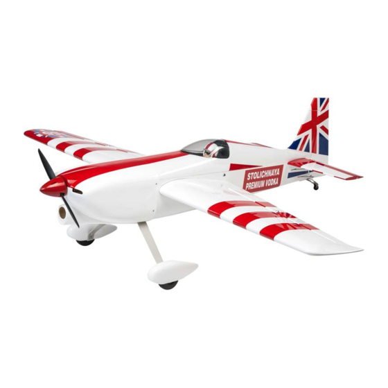
- Seite 2 / cm Servos. Flugerfahrung für Mittel / Fortgeschrittene. servos. Flying skill level Intermediate/advanced. Die Edge 540, Größe 170cm ist für das Sportfliegen und The Edge 540 size 170 is designed for sport flying and Kunstflug konzipiert. aerobatic flying only. Danke für Ihr Interesse an unserem Edge 540.
-
Seite 3: Zusätzliches Benötigtes Zubehör / Additional Items Required
Zusätzliches benötigtes Zubehör / Additional items required • .1.2 cu.in 2-Takt Motor • .1.2 cu.in 2-stroke engine • 4 - 6 digital 6 kg/cm Servos • 4 - 6 digital 6 kg/cm servos • Glow plug to suit engine • Zündkerze •... -
Seite 4: Anhängen Der Querruder / Hinging The Ailerons
This vor dem Kleben ausgerichtet sind! Dadurch wird eine fachge- will ensure proper assembly as the EDGE 540 is made from rechte Montage an der Edge 540 sichergestellt. natural materials. -
Seite 5: Anhängen Der Höhenruder / Hinging The Elevators
7) Wiederholen Sie den Vorgang mit dem anderen Flügel. 7) Repeat this process with the other wing panel, securely hinging the aileron in place. 8) Nachdem beide Querruder fest angehängt sind, stellen Sie 8) After both ailerons are securely hinged, firmly grasp the sicher, dass sie fest geklebt und nicht herausgezogen werden wing panel and aileron to make sure the hinges are securely können. -
Seite 6: Höhenruder Steuerhorn / Elevator Control Horn
Höhenruder Steuerhorn / Elevator control horn 2 sets. 2 sets. 3x45mm. 3x45mm. CONTRONL HORN CONTRONL HORN M3 M3 SCREW Aluminum Washer Epoxy ALUMINUM WASHER EPOX Y. Aluminum Washer M3 LOCK NUT ALUMINUM WASHER M3 LOCK NUT Epoxy. EPOX Y. Horizontal Stabilizer. -
Seite 7: Steuerruder Steuerhorn / Rudder Control Horn
Steuerruder Steuerhorn / Rudder control horn Rudder c ontrol horn. Motor Installation / Engine mount installation Beachten Sie die folgenden Illustrationen und stellen Sie See pictures below.Make yourself the template of your engi- sicher die richtige Zeichnung für Ihr Motor zu haben. ne on paper. - Seite 8 Vent tube. Fuel pick up tube. Fuel fill tube. 4) Test fit the stopper assembly into thetank. It may be neces- 4) Passen Sie die Anschlagsanordnung testweise an den Be- hälter an. Es kann notwendig sein, etwas von dem abstehen- sary to remove some of the flashing around the tank opening den um die Tanköffnung mit einem Bastelmesser zu entfer- using a modeling knife.
-
Seite 9: Installation Der Batterie / Installing The Battery
Installation der Batterie / Installing the battery Battery. Tie Wrap. Installation der Räder und Radverkleidung / Wheel and wheel pants installation 1) Montieren Sie die Radverkleidung wie in den folgenden Bil- 1) Assemble and mounting the wheel pants as shown in the dern. - Seite 10 Landing Gear. wheel Pant. Locker glue. 2) Ein Tropfen C/A -Kleber an den Rad Halsschrauben sichert 2) A drop of C/A glue on the wheel collar screws will help keep sie, damit beim Montieren nichts verrutscht. them from coming lose during operation. Installation des Hauptfahrwerks / Installing the main landing gear 1) Die Blindmuttern um das Hauptfahrwerk zu sichern, sind im 1) The blind nuts for securing the landing gear are already...
- Seite 11 Montage des Motors / Mounting the engine 1) Installieren Sie das Gestängegehäuse an die vorgebohrten 1) Install the pushrod housing through the predrilled hole in Löcher. Das Gestängegehäuse sollte 1/4“ aus dem Gehäuse the firewall and into the servo compartment. The pushrod hervorstehen.
-
Seite 12: Installation Der Motorhaube / Cowling Installation
Installation der Motorhaube / Cowling Installation 1) Schieben Sie die GFK-Motorhaube über den Motor und 1) Slide the fiberglass cowl over the engine and line up the richten Sie die hintere Kante der Motorhaube an den Markie- back edge of the cowl with the marks you made on the fuse- rungen des Rumpfes. - Seite 13 Installation des Spinners / Spinner installation Installieren Sie die Spinner Rückenplatte, Propeller und Spin- Install the spinner backplate, propeller and nerkonus. spinner cone. 1.5mm were (needle valve). Machine Screw 3x10mm. Installation des Spinners / Spinner installation Installieren Sie den Schalter in das vorgeschnittene Loch an Install the switch into the precut hole in the side of fuselage.
-
Seite 14: Installation Der Rumpf-Servos / Installing The Fuselage Servo
Installation der Rumpf-Servos / Installing the fuselage servo 1) Installieren Sie die Gummiösen und die Messingspannzan- 1) Install the rubber grommets and brass collets onto the gen auf das Gasservo. throttle servo. Test fit the servo into the aileron servo mount. 2) Sichern Sie die Servos mit den mitgelieferten Schrauben 2) Secure the servos with the screws provided with your radio system. - Seite 15 Installation des Schubarm-Servo / Vertical stabilizer installation Entfernen Sie die Abdeckung wie in den Bildern gezeigt. Remove the covering a picture shown below. Remove the covering. Remove covering. Masking tape. Remove the covering. Fill epoxy. Hinge slot. Epoxy.
- Seite 16 Hinge. Covering strip. Covering strip. Hinge. C/A glue.
-
Seite 17: Installation Der Horizontal Flosse / Installing Horizontal Fin
Installation der horizontal Flosse / Installing horizontal fin 1) Entfernen Sie die Abdeckung wie in den folgenden Bildern. 1) Remove the covering as same as pictures shown below. 2) Schmirgeln Sie das Aluminiumrohr mit Schmirgelpapier. 2) Sand the aluminium tube using sandpaper. This will impro- Dies wird dem Epoxy eine bessere Klebkraft ermöglichen. -
Seite 18: Installation Der Querruder-Servos / Installing The Aileron Servos
Epoxy. Epoxy. Installation der Querruder-Servos / Installing the aileron servos Instalation der Querruder-Servos wie die Klappen-Servos Installing the aileron servo in place using the same techniques used to flap servo. Servos . Small weight. Thread . String. Small weight. Aileron Servo. - Seite 19 Querruderschubstange Installation / Aileron pushrod horn installation 75mm. M2 clevis. M2 lock nut. 110mm. Wing Wing Aileron Aileron Höhenruderschubstange Installation / Elevator - rudder pushrod horn installation 1) Elevator and rudder pushrods assembly follow pictures be- 1) Für die Installation der Höhenruderschubstange folgen Sie bitte den Bildern.
- Seite 20 Throttle. Elevator. Rudder. Elevator pushrod. Control horn. Elevator Pushrod. Rudder pushrod. M2 lock nut. Metal clevis. 2) Installieren Sie die Gestänge an den Servos. Achten Sie 2) Install servos arm to servos. Notice the position of the servo dabei auf die position wie im folgenden Bild. arms on the servos.
- Seite 21 Anbringung des Heckfahrwerks / Mounting the tail wheel 3x25mm. 3x30mm. 3x30 mm. 3x25 mm. 3x30 mm. Spring. Tail landing gear.
-
Seite 22: Installation Des Batterie-Empfängers / Installing The Battery-Receiver
Installation des Batterie-Empfängers / Installing the battery-receiver 1) Stecken Sie die sechs Servokabel und das Schalterkabel 1) Plug the six servo leads and the switch lead into the recei- in den Empfänger. Verbinden Sie den Akku mit dem Schalter. ver. Plug the battery pack lead into the switch also. 2) Wickeln Sie den Empfänger und Akku-Pack in den Schutz- 2) Wrap the receiver and battery pack in the protective foam rubber to protect them from vibration. - Seite 23 Balance / Balancing 1) Es ist entscheidend, dass das Flugzeug richtig ausgegli- 1) It is critical that your airplane be balanced correctly. Impro- chen ist. Ein Ungleichgewicht wird Ihr Flugzeug zum Absturz per balance will cause your plane to lose control and crash. bringen.
- Seite 24 Sicherheits- und Warnhinweise Safety and Warnings Dieses Modell ist für Modellsportler ab 14 Jahren geeignet This model not a toy, suitable for RC model pilots aged 14 und kein Spielzeug years or older Vor Inbetriebnahme ist das Modell gemäß dieser Assemble the model according to these instructions Bedienungsanleitung vollständig zu montieren completely before use...
- Seite 25 Garantiebedingungen Terms of Guarantee Die Garantiezeit beträgt zwei Jahre ab The warranty period is two years from date Kaufdatum. Die Garantie gilt auf dem Gebiet der of purchase. The warranty applies to the territory of the EU Europäischen Union und der Schweiz. and Switzerland.
- Seite 26 Anleitung Version 1.0, 09.12.2015 CN Development & Media Haselbauer und Piechowski GbR Am Hasselt 20c • 24576 Bad Bramstedt Phone: +49 4192 891 90 83 • Fax: +49 4192 891 90 85 E-Mail: info@yuki-model.com • Web: www.yuki-model.com...