Inhaltsverzeichnis
Werbung
Verfügbare Sprachen
Verfügbare Sprachen
Montage- und Installationsanleitung
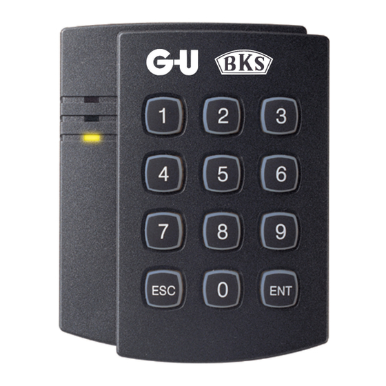
Zutrittskontroll-Steuergerät C-S P 100, C-S A 100
Montage- und Installationsanleitung
Zutrittskontroll-Steuergerät
Montage- und Installationsanleitung, Ausgabe B vom 23/06/2010
Copyright © G-U GmbH, 2010. All rights reserved.
C-S P 100
C-S A 100
Seite 1 von 48
C 59 501 132
Werbung
Kapitel
Inhaltsverzeichnis

Inhaltszusammenfassung für G-U BKS C-S P 100
- Seite 1 Montage- und Installationsanleitung Zutrittskontroll-Steuergerät C-S P 100, C-S A 100 Montage- und Installationsanleitung Zutrittskontroll-Steuergerät C-S P 100 C-S A 100 Montage- und Installationsanleitung, Ausgabe B vom 23/06/2010 Seite 1 von 48 Copyright © G-U GmbH, 2010. All rights reserved. C 59 501 132...
-
Seite 2: Inhaltsverzeichnis
Montage- und Installationsanleitung Zutrittskontroll-Steuergerät C-S P 100, C-S A 100 Inhaltsverzeichnis Verwendete Abkürzungen ................3 Sicherheitshinweise ..................4 Technische Daten....................5 Lieferumfang...................... 5 Montage......................6 Anschluss ......................7 Anschlussbeispiele ................... 8 Anschluss von Kartenleser außen und Freigabeelement ......8 Anschluss von Kartenleser außen und Secury mit A-Öffner ......8 maximale Anschlussmöglichkeiten............... -
Seite 3: Verwendete Abkürzungen
Montage- und Installationsanleitung Zutrittskontroll-Steuergerät C-S P 100, C-S A 100 12.13 Aktivierung des Schnell-Zugangsmodus (Zutritt ohne Prüfung der Zutrittsberechtigung) .................. 18 12.14 Deaktivierung des Schnell-Zugangsmodus ..........18 12.15 Aktivierung des Schritt-Schalt-Modus (Toggle-Modus) ......18 12.16 Deaktivierung des Schritt-Schalt-Modus (Toggle-Modus) ......19 12.17 Türkontaktauswertung aktivieren.............. -
Seite 4: Sicherheitshinweise
Montage- und Installationsanleitung Zutrittskontroll-Steuergerät C-S P 100, C-S A 100 Sicherheitshinweise Vor jeder Montage, Reparatur, Wartungs- oder Einstellarbeit sind alle zugehöri- gen Netzteile spannungslos zu schalten und gegen unbeabsichtigtes Wiederein- schalten abzusichern. Der elektrische Anschluss darf nur von ausgebildetem Fachpersonal vorgenom- men werden. -
Seite 5: Technische Daten
Montage- und Installationsanleitung Zutrittskontroll-Steuergerät C-S P 100, C-S A 100 Technische Daten Modell C-S P 100, C-S A 100 8 Bit Mikroprozessor Speicher Programm-Speicher 20 KByte ROM Datenspeicher 2 KByte ROM Anzahl Nutzer 512 Nutzer Spannung/Strom DC 12 V, 0,2 A... -
Seite 6: Montage
Montage- und Installationsanleitung Zutrittskontroll-Steuergerät C-S P 100, C-S A 100 Montage Der elektrische Anschluss ist entsprechend den im Errichtungsland geltenden Bestimmungen durchzuführen und darf nur von Fachpersonal durchgeführt werden. Entnehmen Sie das Zutrittskontroll-Steuergerät der Verpackung. Befestigen Sie die Montageplatte an einer ebenen Fläche. Verwenden Sie entweder die beigepackten Blechschrauben oder die M3-Schrauben zur Befestigung. -
Seite 7: Anschluss
Montage- und Installationsanleitung Zutrittskontroll-Steuergerät C-S P 100, C-S A 100 Anschluss Stecker Signal Aderfarbe 2-fach (J1) Spannung (+12V) Masse (GND) Schwarz 10-fach (J2) Ausgang Tür-Öffner-Relais (COM) Grau/Rot Ausgang Tür-Öffner-Relais (NC) Blau/Weiß Ausgang Tür-Öffner-Relais (NO) Weiß/Rot Ausgang Alarm-Relais (COM) Weiß Ausgang Alarm-Relais (NC) Violett/Weiß... -
Seite 8: Anschlussbeispiele
Montage- und Installationsanleitung Zutrittskontroll-Steuergerät C-S P 100, C-S A 100 Anschlussbeispiele Zur Verlängerung der Leseranschlussleitungen liegen eine entsprechende Anzahl an Stoßverbindern den Produkten bei. Zur bauseitigen Verlängerung der Anschluss- leitung empfehlen wir Telekommunikationsleitung vom Typ J-Y(ST)Y 2 x 2 x 0.8. Die max. -
Seite 9: Maximale Anschlussmöglichkeiten
Montage- und Installationsanleitung Zutrittskontroll-Steuergerät C-S P 100, C-S A 100 7.3 maximale Anschlussmöglichkeiten Initialisierung/Reset Jedes Zutrittskontroll-Steuergerät sollte vor der Inbetriebnahme initialisiert werden. Hierbei werden die Grundeinstellungen Herstellers geladen. Alle gespeicherten Daten werden gelöscht. Dieses Vorgehen eignet sich auch zum Reset mit Löschung des Gesamtspeichers bei Verlust der Masterkarte: 1. -
Seite 10: Festlegen Des Betriebsmodus
Montage- und Installationsanleitung Zutrittskontroll-Steuergerät C-S P 100, C-S A 100 8.1 Festlegen des Betriebsmodus Durch Drücken Tastenfolge 0, 1 und ENT legen fest, dass Zutrittskontroll-Steuergerät nur RFID-Karten zur Prüfung der Zutrittsberechtigung akzeptiert. Mit der Tastenfolge 0, 2 und werden RFID-Karten immer zusammen mit einer vom Nutzer einzugebenden PIN geprüft. -
Seite 11: Betriebsmodus 3: Registrierung Über Pin
Montage- und Installationsanleitung Zutrittskontroll-Steuergerät C-S P 100, C-S A 100 8.4 Betriebsmodus 3: Registrierung über PIN 1. Initialisierung durchführen. Nach der Initialisierung müssen alle 3 LEDs im Gleichtakt blinken. 2. Durch Drücken der Tastenfolge 0, 3 und ENT legen Sie fest, daß das Zutrittskontrollsteuergerät einen 4-6 stelligen PIN-Code zur Prüfung der... -
Seite 12: Werkseinstellungen
Montage- und Installationsanleitung Zutrittskontroll-Steuergerät C-S P 100, C-S A 100 Im Falle einer Bedrohung geben Sie das 2-stellige Bedrohungs- Passwort (Werkseinstellung 00) vor der Lesung der Karte ein und die Tür öffnet sich wie üblich. Jedoch wird der Bedrohungs- Alarm (TTL-Ausgang) aktiviert und bei entsprechender Installation das Sicherheitspersonal benachrichtigt. -
Seite 13: Nutzer Hinzufügen
Montage- und Installationsanleitung Zutrittskontroll-Steuergerät C-S P 100, C-S A 100 10 Nutzer hinzufügen 10.1 Hinzufügen von RFID-Karten Masterkarte Kommando neue Nutzerkarten Masterkarte 10.2 Hinzufügen von RFID-Karten + PIN Masterkarte Kommando neue Nutzerkarten + PIN Masterkarte 10.3 Hinzufügen von Nutzer-PINs Master-PIN... -
Seite 14: Nutzer Löschen
Montage- und Installationsanleitung Zutrittskontroll-Steuergerät C-S P 100, C-S A 100 11 Nutzer Löschen 11.1 Löschen von RFID-Karten Masterkarte Kommando zu löschende Nutzerkarten Masterkarte 11.2 Löschen von Nutzer-PINs Master-PIN Kommando zu löschende PIN-Nr. Abschließen 11.3 Gezieltes Löschen von einzelnen Karten Sie können z.B. bei Verlust einer Nutzerkarte diese Löschen, ohne dass die Karte verfügbar ist. -
Seite 15: Erweiterte Einstellungen
Montage- und Installationsanleitung Zutrittskontroll-Steuergerät C-S P 100, C-S A 100 12 Erweiterte Einstellungen Sie haben in den erweiterten Einstellungen die Möglichkeit, verschiedene Zustände der Zutrittskontrollsteuerung zu konfigurieren. Sie können über den Ausgangs-Modus festlegen, welcher Ausgang bei welchem Ereignis oder aktiven Eingang geschaltet wird. -
Seite 16: Änderung Der Alarmzeit Bei Unterbrechung Des Türkontakts
Montage- und Installationsanleitung Zutrittskontroll-Steuergerät C-S P 100, C-S A 100 12.4 Änderung der Alarmzeit bei Unterbrechung des Türkontakts (Siehe Tabelle für OM, tt = 00 - 99 s) Der Türkontakt ist standardmäßig als Öffner konfiguriert. Die Verzögerungszeit der Türkontaktauswertung muss eingestellt sein, siehe dazu 12.26. Diese Funktion ist nicht gleichzeitig mit 12.17 (Türkontaktauswertung) möglich! -
Seite 17: Änderung Der Alarmzeit Nach Auslösung Des Bedrohungsalarms
Montage- und Installationsanleitung Zutrittskontroll-Steuergerät C-S P 100, C-S A 100 12.8 Änderung der Alarmzeit nach Auslösung des Bedrohungsalarms Hier legen Sie die Schaltdauer des TTL-Ausgangs bei einem Bedrohungsalarm fest. (tt = 00 - 99 s, Werkseinstellung TTL-Zeit = 03 s, Deaktiv bei tt = 00) -
Seite 18: Aktivierung Dauerfreigabe
Montage- und Installationsanleitung Zutrittskontroll-Steuergerät C-S P 100, C-S A 100 12.11 Aktivierung Dauerfreigabe Die Tür ist dauerhaft freigegeben. Karten/PIN’s werden nicht gelesen. Diese Funktion einer Masterkarte immer schaltbar! Masterkarte Kommando 12.12 Deaktivierung der Dauerfreigabe Masterkarte Kommando 12.13 Aktivierung des Schnell-Zugangsmodus (Zutritt ohne Prüfung der Zutrittsberechtigung) -
Seite 19: Deaktivierung Des Schritt-Schalt-Modus (Toggle-Modus)
Montage- und Installationsanleitung Zutrittskontroll-Steuergerät C-S P 100, C-S A 100 12.16 Deaktivierung des Schritt-Schalt-Modus (Toggle-Modus) Masterkarte Kommando 12.17 Türkontaktauswertung aktivieren Wird die Türkontaktauswertung aktiviert, schaltet das Türöffner-Relais bei geöffneter Tür permanent. Wird die Tür wieder geschlossen, fällt das Türöffner-Relais wieder ab. Wird die Tür bei einer Freigabe nicht ge- öffnet, so schaltet das Türöffner-Relais für die vorge-... -
Seite 20: Änderung Der Abschaltdauer Der Tastatur Nach Einer Mehrfach-Falscheingabe
Montage- und Installationsanleitung Zutrittskontroll-Steuergerät C-S P 100, C-S A 100 12.21 Änderung der Abschaltdauer der Tastatur nach einer Mehrfach- Falscheingabe (mm = 00 - 99 min, Werkseinstellung = 01 min) Masterkarte Kommando Abschaltdauer in Minuten 12.22 Eingangs-Einstellungen Masterkarte Kommandos Auswertung der steigenden Flanke (Schließerkontakt) am Hilfseingang Aux 1 Auswertung der fallenden Flanke (Öffnerkontakt) am Hilfseingang Aux 1... -
Seite 21: Ausgangs-Einstellungen
Montage- und Installationsanleitung Zutrittskontroll-Steuergerät C-S P 100, C-S A 100 12.23 Ausgangs-Einstellungen Masterkarte Kommandos TTL-Ausgang ändert seinen Status von logisch 0 zu logisch 1 (Schließerkontakt) bei Aktivierung. TTL-Ausgang ändert seinen Status von logisch 1 zu logisch 0 (Öffnerkontakt) bei Aktivierung (Werkseinstellung). -
Seite 22: Begrenzung Der Anzahl Der Möglichen Falscheingaben
Montage- und Installationsanleitung Zutrittskontroll-Steuergerät C-S P 100, C-S A 100 12.27 Begrenzung der Anzahl der möglichen Falscheingaben (NN = 00 - 99, Werkseinstellung Anzahl = 05) Masterkarte Kommando Anzahl der möglichen Falscheingaben 12.28 Zeitfenster für Codeeingabe (tt = 10 - 99 s, Werkseinstellung Zeitfenster = 20 s Minimum tt = 10 s) Masterkarte Kommando Zeitfenster für Codeeingabe... -
Seite 23: Zurücksetzen Auf Werkseinstellung Und Löschen Aller
Montage- und Installationsanleitung Zutrittskontroll-Steuergerät C-S P 100, C-S A 100 12.32 Zurücksetzen Werkseinstellung Löschen aller Zutrittsberechtigungen Bitte benutzen Sie dieses Kommando, wenn Sie alle eingegebenen Daten löschen und neu beginnen wollen. Anschließend beginnen Sie mit der Eingabe der Masterkarte oder des Master-PIN’s wie unter Kapitel 8 beschrieben. -
Seite 24: Kontakt
Montage- und Installationsanleitung Zutrittskontroll-Steuergerät C-S P 100, C-S A 100 Kontakt Internet http://www.g-u.de oder http://www.bks.de. Telefonnummern bei Fragen zu den Produkten: +49 7156 301 0 oder +49 2051 201 0 Hinweis Inhaltliche Änderungen dieses Dokuments behalten wir uns ohne Ankündigung vor. -
Seite 25: Installation Instructions
Installation Instructions Access Control Unit C-S P 100, C-S A 100 Installation Instructions Access Control Unit C-S P 100 C-S A 100 Installation Instructions, Edition B dated 23/06/2010 Page 25 of 48 Copyright © G-U GmbH, 2010. All rights reserved. - Seite 26 Installation Instructions Access Control Unit C-S P 100, C-S A 100 Contents Abbreviations ....................27 Safety Advice....................28 Technical Data ....................29 Scope of delivery..................... 29 Installation ....................... 30 Electrical Connection..................31 Connection Examples ..................32 Connecting Outside Card Reader and Door Locking Device ..... 32 Connecting Outside Card Reader and Door Lock SECURY with A-Opener32 Maximal Connections .................
-
Seite 27: Abbreviations
Installation Instructions Access Control Unit C-S P 100, C-S A 100 12.13 Activating the Rapid Access Mode (Access without Authorisation Verification) ....................42 12.14 Deactivating the Rapid Access Mode............42 12.15 Activating the Toggle Mode................ 42 12.16 Deactivating the Toggle Mode..............43 12.17 Activating the Door Contact Evaluation ............ -
Seite 28: Safety Advice
Installation Instructions Access Control Unit C-S P 100, C-S A 100 Safety Advice Before you start doing any installation, repair, service or adjustment work, ensure that no voltage is applied to any of the mains adapters to avoid unintended switch-on. -
Seite 29: Technical Data
Installation Instructions Access Control Unit C-S P 100, C-S A 100 Technical Data Type C-S P 100, C-S A 100 8 Bit microprocessor Memory Program memory 20 KByte ROM Data memory 2 KByte ROM Number of users Voltage/Current DC 12 V, 0.2 A... -
Seite 30: Installation
Installation Instructions Access Control Unit C-S P 100, C-S A 100 Installation The electrical connection may only be carried out by trained personnel and must be performed in compliance with the particular national regulations. Take the control unit from the packing. -
Seite 31: Electrical Connection
Installation Instructions Access Control Unit C-S P 100, C-S A 100 Electrical Connection Connector Signal Wire Colour Voltage (+12 V) Ground (GND) black Output door opener relay (COM) grey/red Output door opener relay (NC) blue/white Output door opener relay (NO) -
Seite 32: Connection Examples
Installation Instructions Access Control Unit C-S P 100, C-S A 100 Connection Examples The connecting cables for the readers can be extended by means of the butt connectors enclosed. For the extension of the local access line we recommend to use telecommunication cable type J-Y(ST)Y 2 x 2 x 0.8. -
Seite 33: Maximal Connections
Installation Instructions Access Control Unit C-S P 100, C-S A 100 7.3 Maximal Connections Initialisation/Reset Before start-up, every Access Control Unit should initialised. During initialisation process, the factory settings of the manufacturer are loaded and all memorised data deleted. This procedure is also suited for reset and total memory deletion in case of loss of the master card. -
Seite 34: Determining The Operating Mode
Installation Instructions Access Control Unit C-S P 100, C-S A 100 8.1 Determining the Operating Mode Press the keys 0, 1 and ENT in sequence to make the access control unit accept RFID cards for authorisation verification. By pressing the keys 0, 2... -
Seite 35: Operating Mode 3: Pin Identification
Installation Instructions Access Control Unit C-S P 100, C-S A 100 8.4 Operating Mode 3: PIN Identification 6. Initialise the control unit as described above. After correct initialisation, all 3 LEDs flash at the same rhythm. 7. By pressing the keys 0, 3 and ENT in sequence, the access control unit is caused to accept a 4 to 6-digit PIN code for authorisation verification. -
Seite 36: Factory Settings
Installation Instructions Access Control Unit C-S P 100, C-S A 100 9.1 Factory Settings Command (keypad entry) Function Default Activate Deactivate Change Page Adding user cards Adding user cards plus PINs Adding user PINs Adding user cards or PINs Deleting users... -
Seite 37: Adding Users
Installation Instructions Access Control Unit C-S P 100, C-S A 100 10 Adding Users 10.1 Adding RFID Cards Master card Keypad entry New user cards Master card 10.2 Adding RFID Cards + PIN Master card Keypad entry New user cards + PIN Master card 10.3 Adding User PINs... -
Seite 38: Deleting User Pins
Installation Instructions Access Control Unit C-S P 100, C-S A 100 11 Deleting User PINs 11.1 Deleting RFID Cards Master card Keypad entry User cards for deletion Master card 11.2 Deleting User PINs Master PIN Keypad entry User PIN for deletion Finish 11.3 Selected Deletion of Individual Cards... -
Seite 39: Extended Setting Functions
Installation Instructions Access Control Unit C-S P 100, C-S A 100 12 Extended Setting Functions A range of extended setting functions allows to configure different statuses of the access control unit. In Output Mode it is possible to determine which output is to be switched at which event or active input. -
Seite 40: Changing The Alarm Switching Time At Interruption Of Door Contact
Installation Instructions Access Control Unit C-S P 100, C-S A 100 12.4 Changing the Alarm Switching Time at Interruption of Door Contact (See table for OM, tt = 00 - 99 s) The door contact is configured as opener as a standard. The time lag of the door contact evaluation must be set, see chapter 12.26. -
Seite 41: Changing The Alarm Switching Time After Released Threat Alarm
Installation Instructions Access Control Unit C-S P 100, C-S A 100 12.8 Changing the Alarm Switching Time after Released Threat Alarm Here you determine the switching time of the TTL output in the event of a threat alarm. (tt = 00 - 99 s, factory-set TTL time = 03 s, deactivated at tt = 00) -
Seite 42: Activating The Permanent Door Release
Installation Instructions Access Control Unit C-S P 100, C-S A 100 12.11 Activating the Permanent Door Release Door released permanently. Cards/PINs are not read. With a master card, this function available at any time ! Master card Keypad entry 12.12 Deactivating the Permanent Door Release Master card Keypad entry 12.13 Activating the Rapid Access Mode... -
Seite 43: Deactivating The Toggle Mode
Installation Instructions Access Control Unit C-S P 100, C-S A 100 12.16 Deactivating the Toggle Mode Master card Keypad entry 12.17 Activating the Door Contact Evaluation If you enable the Door Contact Evaluation, the Door only is locked followed by Door Contact so the door will remain open until the door is completely closed. -
Seite 44: Changing The Keypad Switch-Off Time After Repeated False Entry
Installation Instructions Access Control Unit C-S P 100, C-S A 100 12.21 Changing the Keypad Switch-Off Time After Repeated False Entry (mm = 00 - 99 min, factory setting = 01 min) Master card Keypad entry Switch-off time in minutes 12.22 Input Settings... -
Seite 45: Output Settings
Installation Instructions Access Control Unit C-S P 100, C-S A 100 12.23 Output Settings up to Master card Keypad entries TTL output changes status from logic 0 to logic 1 (closer contact) at activation. TTL output changes status from logic 1 to logic 0 (opener contact) at activation (= factory setting). -
Seite 46: Limiting The Number Of False Entries Allowed
Installation Instructions Access Control Unit C-S P 100, C-S A 100 12.27 Limiting the Number of False Entries Allowed (NN = 00 - 99, factory-set number = 05) Master card Keypad entry Number of false entries allowed 12.28 Time Window for Code Entry (tt = 10 - 99 s, factory-set time window = 20 s. -
Seite 47: Reset To Factory Settings And Deleting All Access Authorisations
Installation Instructions Access Control Unit C-S P 100, C-S A 100 12.32 Reset to Factory Settings and Deleting All Access Authorisations Use this command if you wish to delete all data entered and to restart from the beginning. Afterwards, you start anew by reading in the master card or entering the master PIN as described in chapter 8. -
Seite 48: Installation Instructions, Edition B Dated 23/06/2010
Installation Instructions Access Control Unit C-S P 100, C-S A 100 Contact Internet http://www.g-u.de or http://www.bks.de. If you have any questions concerning the products call the telephone numbers: +49 7156 301 0 or +49 2051 201 0 Advice We reserve the right to change the contents of this document without prior notice.