Endress+Hauser iTEMP TMT162 Bedienungsanleitung
Vorschau ausblenden
Andere Handbücher für iTEMP TMT162:
- Bedienungsanleitung (160 Seiten) ,
- Betriebsanleitung (100 Seiten) ,
- Kurzanleitung (56 Seiten)
Inhaltsverzeichnis
Werbung
Verfügbare Sprachen
Verfügbare Sprachen
Quicklinks
KA00250R/09/A2/02.17
71372089
Products
Brief Operating Instructions
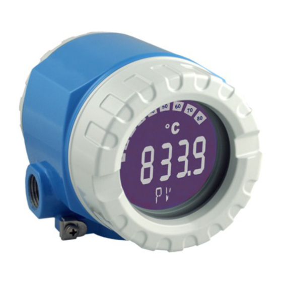
iTEMP TMT162
Temperature field transmitter
These Instructions are Brief Operating Instructions; they are
not a substitute for the Operating Instructions pertaining to
the device.
For detailed information, refer to the Operating Instructions
and other documentation.
Available for all device versions via:
• Internet: www.endress.com/deviceviewer
• Smart phone/Tablet: Endress+Hauser Operations App
Solutions
Services
Werbung
Kapitel
Inhaltsverzeichnis

Verwandte Anleitungen für Endress+Hauser iTEMP TMT162


Inhaltszusammenfassung für Endress+Hauser iTEMP TMT162
- Seite 1 These Instructions are Brief Operating Instructions; they are not a substitute for the Operating Instructions pertaining to the device. For detailed information, refer to the Operating Instructions and other documentation. Available for all device versions via: • Internet: www.endress.com/deviceviewer • Smart phone/Tablet: Endress+Hauser Operations App...
- Seite 2 TMT162 Order code: XXXXX-XXXXXX Ser. no.: XXXXXXXXXXXX Ext. ord. cd.: XXX.XXXX.XX Serial number www.endress.com/deviceviewer Endress+Hauser Operations App A0023555 Endress+Hauser...
- Seite 3 TMT162 iTEMP TMT162 Temperature field transmitter Kurzanleitung ............... . . 4 Brief Operating Instructions .
-
Seite 4: Inhaltsverzeichnis
Inhaltsverzeichnis iTEMP TMT162 Inhaltsverzeichnis Wichtige Hinweise zum Dokument ..........4 Funktion und Umgang mit dem Dokument . -
Seite 5: Funktionale Sicherheit
TMT162 Wichtige Hinweise zum Dokument zugehörigen Ex-Dokumentation (XA...) finden Sie auf dem Typenschild. Wenn beide Nummern (auf der Ex-Dokumentation und auf dem Typenschild) exakt übereinstimmen, dürfen Sie diese Ex-Dokumentation benutzen. 1.1.2 Funktionale Sicherheit Für den Einsatz zugelassener Geräte in Schutzeinrichtungen entsprechend IEC 61508 Sicherheitshandbuch SD01632T/09 beachten. -
Seite 6: Symbole Für Informationstypen
Grundlegende Sicherheitshinweise iTEMP TMT162 1.2.3 Symbole für Informationstypen Symbol Bedeutung Symbol Bedeutung Erlaubt Zu bevorzugen Abläufe, Prozesse oder Handlungen, Abläufe, Prozesse oder Handlungen, die erlaubt sind. die zu bevorzugen sind. Verboten Tipp Abläufe, Prozesse oder Handlungen, Kennzeichnet zusätzliche die verboten sind. -
Seite 7: Arbeitssicherheit
Werk in sicherheitstechnisch einwandfreiem Zustand verlassen. Es erfüllt die allgemeinen Sicherheitsanforderungen und gesetzlichen Anforderungen. Zudem ist es konform zu den EG-Richtlinien, die in der gerätespezifischen EG-Konformitätserklärung aufgelistet sind. Mit der Anbringung des CE-Zeichens bestätigt Endress+Hauser diesen Sachverhalt. Endress+Hauser... -
Seite 8: Warenannahme Und Produktidentifikation
Warenannahme und Produktidentifikation iTEMP TMT162 Warenannahme und Produktidentifikation Warenannahme A0024856 Temperaturtransmitter vorsichtig auspacken. Sind Inhalt oder Verpackung unbeschädigt? Beschädigte Komponenten dürfen nicht installiert werden, da der Hersteller andernfalls die Einhaltung der ursprünglichen Sicherheitsanforderungen oder die Materialbeständigkeit nicht gewährleisten und daher auch nicht für daraus entstehende Schäden verantwortlich gemacht werden kann. -
Seite 9: Produktidentifikation
TMT162 Warenannahme und Produktidentifikation TMT162 A0024858 Sind die technische Dokumentation und alle weiteren erforderlichen Dokumente vorhanden? Produktidentifikation Folgende Möglichkeiten stehen zur Identifizierung des Geräts zur Verfügung: • Typenschildangaben • Seriennummer vom Typenschild in W@M Device Viewer eingeben (www.endress.com/ deviceviewer): Alle Angaben zum Gerät und eine Übersicht zum Umfang der mitgelieferten technischen Dokumentation werden angezeigt. -
Seite 10: Lieferumfang
Warenannahme und Produktidentifikation iTEMP TMT162 3.2.2 Lieferumfang Der Lieferumfang des Gerätes besteht aus: • Temperaturtransmitter • Wand- oder Rohrmontagehalter, optional • Blindstopfen • Gedruckte, mehrsprachige Kurzanleitung • Zusätzliche Dokumentation für Geräte, die für den Einsatz im explosionsgefährdeten Bereich (0 1) geeignet sind, wie z.B. Sicherheitshinweise (XA...), Control oder Installation Drawings (ZD...) -
Seite 11: Montage
TMT162 Montage Montage Das Gerät kann bei Verwendung stabiler Sensoren direkt auf den Sensor montiert werden. Für die abgesetzte Montage an Wand- oder Rohr stehen zwei Montagehalter zur Verfügung. Das beleuchtete Display ist in 4 verschiedenen Positionen montierbar. Montagebedingungen 4.1.1... - Seite 12 Montage iTEMP TMT162 4.2.1 Direkte Sensormontage A0024817 2 Direkte Montage des Feldtransmitter am Sensor Schutzrohr Messeinsatz Halsrohrnippel und Adapter Sensorleitungen Feldbusleitungen Feldbus-Schirmleitung Schutzrohr montieren und festschrauben (1). Messeinsatz mit Halsrohrnippel und Adapter in Transmitter schrauben (2). Nippel- und Adaptergewinde mit Silikonband abdichten.
-
Seite 13: Abgesetzte Montage
TMT162 Montage 4.2.2 Abgesetzte Montage (2.2) 72 (2.8) (2.01) 25 (0.98) (6.3) (7.1) ≤ 50 (1.97) 72 (2.8) 10.5 (0.41) A0027188 3 Montage des Feldtransmitters mit Montagehalter, siehe Kap. ’Zubehör’. Abmessungen in mm (in) Montage mit kombinierten Wand-/Rohrmontagehalter Montage mit Rohrmontagehalter 2"/V4A... -
Seite 14: Montagekontrolle
Verdrahtung iTEMP TMT162 Montagekontrolle Führen Sie nach der Montage des Gerätes folgende Kontrollen durch: Gerätezustand und -spezifikationen Hinweise Ist das Gerät unbeschädigt (Sichtkontrolle)? Entsprechen die Umgebungsbedingungen der Gerätespezifikation (z.B. → 11 Umgebungstemperatur, Schutzart, usw.)? Verdrahtung Anschlussbedingungen VORSICHT Elektronik kann zerstört werden ‣... -
Seite 15: Sensor Anschließen
TMT162 Verdrahtung Um Anschlussfehler zu vermeiden, in jedem Fall vor der Inbetriebnahme die Hinweise in der Anschlusskontrolle beachten! Sensor anschließen HINWEIS ‣ ESD - Electrostatic discharge. Klemmen vor elektrostatischer Entladung schützen. Ein Nichtbeachten kann zur Zerstörung oder Fehlfunktion von Teilen der Elektronik führen. -
Seite 16: Messgerät Anschließen
Verdrahtung iTEMP TMT162 Bei Belegung beider Sensoreingänge sind folgende Anschlusskombinationen möglich: Sensoreingang 1 Thermoelemen RTD oder RTD oder RTD oder t (TC), Widerstandsge Widerstandsge Widerstandsge Spannungsgeb ber, 2-Leiter ber, 3-Leiter ber, 4-Leiter RTD oder Widerstandsgeber, 2- Leiter... -
Seite 17: Anschluss Hart®-Kommunikationswiderstand
TMT162 Verdrahtung A0010823 5 Geräteanschluss an die Feldbusleitung Feldbus Anschlussklemmen - Feldbus-Kommunikation und Spannungsversorgung Abgeschirmtes Feldbuskabel Erdungsklemmen innen Erdungsklemme (aussen, für Getrenntausführung relevant) 5.3.2 Anschluss HART®-Kommunikationswiderstand Ist der HART® -Kommunikationswiderstand nicht im Speisegerät eingebaut, muss notwendigerweise ein Kommunikationswiderstand von 250 Ω in die 2-Draht-Leitung eingebaut werden. -
Seite 18: Schirmung Und Erdung
Verdrahtung iTEMP TMT162 ³ 250 W PMC731: PIC0001 Online 1 >Group Select 2 PV 0.7 bar HELP SEND HOME A0033549 6 HART®-Anschluss mit anderen Speisegeräten, in denen der HART®-Kommunikationswiderstand nicht eingebaut ist Temperaturfeldtransmitter HART®-Kommunikationswiderstand SPS/PLS Konfigurationssoftware, z. B. FieldCare HART®... -
Seite 19: Spezielle Anschlusshinweise
TMT162 Verdrahtung A0010984 7 Schirmung und einseitige Erdung des Signalkabels bei HART®-Kommunikation Speisegerät Erdungspunkt für HART®-Kommunikation-Kabelschirm Einseitige Erdung des Kabelschirms Optionale Erdung des Feldgerätes, isoliert vom Kabelschirm Spezielle Anschlusshinweise Ist das Gerät mit einem Überspannungsschutzmodul ausgerüstet, erfolgt der Busanschluss und die Spannungsversorgung über die Schraubklemmen am Überspannungsschutzmodul. -
Seite 20: Schutzart Sicherstellen
Verdrahtung iTEMP TMT162 Schutzart sicherstellen Das Gerät erfüllt alle Anforderungen gemäß Schutzart IP67. Um nach erfolgter Montage im Feld oder nach einem Servicefall die Schutzart IP67 zu gewährleisten, müssen folgende Punkte zwingend beachtet werden: • Die Gehäusedichtungen müssen sauber und unverletzt in die Dichtungsnut eingelegt werden. -
Seite 21: Bedienmöglichkeiten
10 Bedienungsmöglichkeiten des Gerätes Hardware-Einstellungen via DIP-Schalter und Proof-Test-Taster HART® Handheld Kommunikator SPS/PLS Konfigurationssoftware, z. B. FieldCare Commubox: Spannungsversorgung und Modem für Feldgeräte mit HART®-Protokoll Konfiguration via Field Xpert SFX350/370 Speisegerät bzw. -trenner, z. B. RN221 von Endress+Hauser Endress+Hauser... -
Seite 22: Bedienung Vor Ort
Bedienmöglichkeiten iTEMP TMT162 6.1.1 Messwertanzeige- und Bedienelemente Anzeigeelemente °F °C A0034101 11 LC-Anzeige des Feldtransmitters (beleuchtet, steckbar in 90°-Schritten) Pos.-nr. Funktion Beschreibung Bargraphanzeige In 10%-Schritten mit Marken für Messbereichsunter- / überschreitung. Symbol ’Achtung’ Diese Anzeige erscheint bei Fehler oder Warnung. - Seite 23 TMT162 Bedienmöglichkeiten Pr oo f- OF F Te st W RI TE LO CK 3 mm A0033847 Vorgehensweise zur DIP-Schalter Einstellung oder ' P roof-Test' Aktivierung: Deckelkralle entfernen. Den Gehäusedeckel zusammen mit dem O-Ring abschrauben. Gegebenenfalls das Display mit Halterung vom Elektronikmodul abziehen.
-
Seite 24: Zugriff Auf Bedienmenü Via Bedientool
TMT162 Zugriff auf Bedienmenü via Bedientool Die Konfiguration des Transmitters und die Messwertabfrage erfolgen über das HART ® Protokoll oder CDI (= Endress+Hauser Common Data Interface) -Schnittstelle. Dafür stehen folgende Bedientools zur Verfügung: Bedientools FieldCare, DeviceCare, Field Xpert SIMATIC PDM... - Seite 25 TMT162 Inbetriebnahme Das Gerät arbeitet nach ca. 30 Sekunden im Normalbetrieb! Nach erfolgreichem Einschaltvorgang wird der normale Messbetrieb aufgenommen. Auf dem Display erscheinen Mess- und/oder Statuswerte. Endress+Hauser...
-
Seite 26: Important Document Information
Table of contents iTEMP TMT162 Table of contents Important document information ..........26 Function of document and how to use . -
Seite 27: Functional Safety
TMT162 Important document information the nameplate. If the two numbers (on the Ex documentation and the nameplate) are identical, then you may use this Ex-specific documentation. 1.1.2 Functional safety Please refer to Safety Manual SD01632T/09 for the use of approved devices in protective systems according to IEC 61508. -
Seite 28: Registered Trademarks
Basic safety instructions iTEMP TMT162 1.2.3 Symbols for certain types of information Symbol Meaning Symbol Meaning Permitted Preferred Procedures, processes or actions that Procedures, processes or actions that are permitted. are preferred. Forbidden Procedures, processes or actions that Indicates additional information. -
Seite 29: Workplace Safety
It meets general safety standards and legal requirements. It also complies with the EC directives listed in the device-specific EC Declaration of Conformity. Endress+Hauser confirms this by affixing the CE mark to the device. Endress+Hauser... -
Seite 30: Incoming Acceptance And Product Identification
Incoming acceptance and product identification iTEMP TMT162 Incoming acceptance and product identification Incoming acceptance A0024856 Unpack the temperature transmitter carefully. Is the packaging or content damaged? Damaged components may not be installed as the manufacturer can otherwise not guarantee compliance with the original safety requirements or the material resistance, and can therefore not be held responsible for any resulting damage. -
Seite 31: Product Identification
TMT162 Incoming acceptance and product identification TMT162 A0024858 Are the technical documentation and all other necessary documents provided? Product identification The following options are available for identification of the device: • Nameplate specifications • Enter the serial number from the nameplate in the W@M Device Viewer (www.endress.com/deviceviewer): All data relating to the device and an overview of the... -
Seite 32: Scope Of Delivery
Incoming acceptance and product identification iTEMP TMT162 3.2.2 Scope of delivery The scope of delivery of the device comprises: • Temperature transmitter • Wall or pipe mounting bracket, optional • Dummy plugs • Hard copy of multi-language Brief Operating Instructions •... -
Seite 33: Installation
TMT162 Installation Installation If stable sensors are used, the device can be fitted directly to the sensor. For remote mounting to a wall or stand pipe, two mounting brackets are available. The illuminated display can be mounted in four different positions. - Seite 34 Installation iTEMP TMT162 4.2.1 Direct sensor mounting A0024817 2 Direct field transmitter mounting on sensor Thermowell Insert Neck tube nipple and adapter Sensor cables Fieldbus cables Fieldbus shielded cable Mount the thermowell and screw down (1). Screw the insert with the neck tube nipple and adapter into the transmitter (2). Seal the nipple and adapter thread with silicone tape.
-
Seite 35: Remote Mounting
TMT162 Installation 4.2.2 Remote mounting (2.2) 72 (2.8) (2.01) 25 (0.98) (6.3) (7.1) ≤ 50 (1.97) 72 (2.8) 10.5 (0.41) A0027188 3 Installation of the field transmitter using the mounting bracket, see chapter ' A ccessories' . Dimensions in mm (in) Mounting with combined wall/pipe mounting bracket Mounting with pipe mounting bracket 2"/V4A... -
Seite 36: Post-Installation Check
Wiring iTEMP TMT162 Post-installation check After installing the device, always run the following final checks: Device condition and specifications Notes Is the device undamaged (visual inspection)? Do the ambient conditions match the device specification (e.g. ambient temperature, degree of → 33 protection, etc.)? -
Seite 37: Connecting The Sensor
TMT162 Wiring Connecting the sensor NOTICE ‣ ESD - electrostatic discharge. Protect the terminals from electrostatic discharge. Failure to observe this may result in destruction or malfunction of parts of the electronics. Terminal assignment Sensor 1 Bus connection and... -
Seite 38: Connecting The Measuring Device
Wiring iTEMP TMT162 The following connection combinations are possible when both sensor inputs are assigned: Sensor input 1 RTD or RTD or RTD or Thermocouple resistance resistance resistance (TC), voltage transmitter, transmitter, transmitter, transmitter two-wire three-wire four-wire RTD or resistance ... - Seite 39 TMT162 Wiring A0010823 5 Connecting the device to the fieldbus cable Fieldbus terminals - fieldbus communication and power supply Shielded fieldbus cable Ground terminals, internal Ground terminal (external, relevant for remote version) 5.3.2 Connecting the HART® communication resistor If the HART®...
-
Seite 40: Shielding And Grounding
Wiring iTEMP TMT162 ³ 250 W PMC731: PIC0001 Online 1 >Group Select 2 PV 0.7 bar HELP SEND HOME A0033549 6 HART® connection with other power supply units that do not have a built-in HART® communication resistor Temperature field transmitter HART®... -
Seite 41: Special Connection Instructions
TMT162 Wiring A0010984 7 Shielding and grounding the signal cable at one end with HART® communication Supply unit Grounding point for HART® communication cable shield Grounding of the cable shield at one end Optional grounding of the field device, isolated from cable shielding... -
Seite 42: Ensuring The Degree Of Protection
Wiring iTEMP TMT162 Ensuring the degree of protection The measuring system meets all the requirements of IP67 protection. Compliance with the following points is mandatory following installation in the field or servicing in order to ensure that IP67 protection is maintained: •... -
Seite 43: Operating Options
Hardware settings via DIP switch and proof-test button HART® handheld communicator PLC/DCS Configuration software, e.g. FieldCare Commubox: Power supply and modem for field devices with HART® protocol Configuration via Field Xpert SFX350/370 Power supply unit and active barrier, .e.g. RN221 from Endress+Hauser Endress+Hauser... -
Seite 44: Local Operation
Operating options iTEMP TMT162 6.1.1 Display and operating elements Display elements °F °C A0034101 11 LC display of the field transmitter (backlit, attachable in 90° stages) Item No. Function Description Bar graph display In increments of 10% with indicators for underranging and overranging. - Seite 45 TMT162 Operating options Pr oo f- OF F Te st W RI TE LO CK 3 mm A0033847 Procedure for setting the DIP switch or activating the proof test: Remove the cover clamp. Unscrew the housing cover together with the O-ring.
-
Seite 46: Access To The Operating Menu Via The Operating Tool
Access to the operating menu via the operating tool The transmitter and measured value display are configured via the HART ® protocol or CDI (= Endress+Hauser Common Data Interface). The following operating tools are available for this purpose: Operating tools FieldCare, DeviceCare, Field Xpert... - Seite 47 TMT162 Commissioning The device operates in normal mode after approx. 30 seconds! Normal measuring mode commences as soon as the switch-on procedure is completed. Measured values and status values appear on the display. Endress+Hauser...
- Seite 48 www.addresses.endress.com...