Anmelden
Hochladen
Anleitungen
Marken
Bosch Anleitungen
Industrielle Ausrüstung
EPS 807
Bosch EPS 807 Handbücher
Anleitungen und Benutzerhandbücher für Bosch EPS 807. Wir haben
1
Bosch EPS 807 Anleitung zum kostenlosen PDF-Download zur Verfügung: Originalbetriebsanleitung
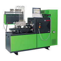
Bosch EPS 807 Originalbetriebsanleitung (336 Seiten)
Einspritzpumpenprüfstand
Marke:
Bosch
| Kategorie:
Industrielle Ausrüstung
| Dateigröße: 18.51 MB
Inhaltsverzeichnis
Deutsch
4
Contents English
3
Inhaltsverzeichnis
4
1 Verwendete Symbolik
5
In der Dokumentation
5
Warnhinweise - Aufbau und Bedeutung
5
Symbole - Benennung und Bedeutung
5
Auf dem Produkt
5
2 Benutzerhinweise
6
Wichtige Hinweise
6
Sicherheitshinweise
6
Elektromagnetische Verträglichkeit (EMV)
6
Produktbeschreibung
6
Bestimmungsgemäße Verwendung
6
Voraussetzungen
6
Lieferumfang
7
Sonderzubehör
7
Gerätebeschreibung
8
Antrieb
8
Schaltschrank, Bedienteil
8
Frontplatte
9
Symbole
9
Druckregelventil
10
Prüfölversorgung
10
Prüfölkühlung
10
Prüfölheizung
10
Spannungsversorgung 12/24 Volt
11
Schmierölversorgung (Sonderzubehör)
11
4 Erstinbetriebnahme
12
Transportieren, Aufstellen
12
Transportsicherungen Entfernen
12
Netzanschluss
13
Kühlwasseranschluss
14
Prüföl Einfüllen
14
Schmieröl Einfüllen
14
Überprüfung Drehrichtung
14
5 Bedienung
15
Einschalten
15
Ausschalten
15
Not-Aus
15
Not-Aus Aktivieren
15
Not-Aus Deaktivieren
15
Vorbereitung zum Prüfen
16
Prüfen von Vorhub, Förderbeginn, und Nockenversatz bei Reihenpumpen
17
Prüfen von Förderbeginn bei Verteilerpumpen mit Vorhubangabe
18
6 Instandhaltung
19
Reinigung
19
Prüföl, Prüffilter
19
Schmutzöl
19
Wartung
19
Wartungsintervalle
20
6.4 Ersatz- und Verschleißteile
20
Antriebskupplung 1 686
20
Außerbetriebnahme
21
Vorübergehende Stilllegung
21
Antriebskupplung 1 686 401 024
22
Technische Daten
22
Abmessungen und Ausführungen
22
Anzugsmomente für Spannschrauben
22
Zulässige Temperaturbereiche
23
Zulässige Drehmomente an der Kupplung
23
Drücke und Füllmengen
23
12 9.6 Abmessungen EPS
24
English
26
1 Symbols Used
27
In the Documentation
27
Warning Notices - Structure and Meaning
27
Symbols in this Documentation
27
On the Product
27
Product Description
28
Application
28
Requirements
28
Extent of Delivery
29
Special Accessories
29
Description of the Unit
30
Drive
30
Control Cabinet, Control Unit
30
Front Panel
31
Summarised Instructions
31
Pressure Control Valve for High and Low Pressure
32
Supplying the Calibration Fluid
32
Cooling the Calibration Fluid
32
Heating the Calibration Fluid
32
Voltage Supply for Start/Stop Magnets
33
Lubricating-Oil Supply (Optional Accessory)
33
2 User Information
28
Important Notes
28
Safety Instructions
28
Electromagnetic Compatibility (EMC)
28
4 Initial Start-Up
34
Transportation, Installation
34
Removing Transportation Safeguards
34
Mains Connection
35
Connection for Cooling Water
36
Filling up with Calibration Fluid
36
Adding Lubricating Oil
36
Checking the Direction of Rotation
36
5 Operation
37
Switch-On
37
Switch-Off
37
Emergency Stop
37
Activating Emergency Stop
37
Deactivating Emergency Stop
37
Preparing to Carry out Tests
38
Checking Prestroke, Start of Delivery and Cam Offset for In-Line Pumps
39
Checking Start of Delivery for Distributor Pumps with Prestroke Specifications
40
Calibration Fluid, Calibration-Fluid Filter
41
Contaminated Oil
41
27 6.3 Maintenance Intervals
42
Spare Parts and Wearing Parts
42
28 7.1 Temporary Shutdown
43
28 7.2 Change of Location
43
Disposal and Scrapping
43
28 7.3.1 Substances Hazardous to Water
43
28 7.3.2 EPS 807 / 815 and Accessories
43
29 8. Tightening Torques
43
29 8.1 Fastening Parts
43
30 8.2 Coupling Halves
43
30 8.3 Intermediate Flange 1 685
43
Drive Clutch
44
Drive Clutch 1 686 401 024
44
Technical Data
44
Tightening Torques for the Tensioning Bolt
44
Test-Bench Colour
45
9.6 Dimensions EPS
46
34 9.7 Machinery Noise Information
47
Français
48
1 Symboles Utilisés
49
Dans la Documentation
49
Avertissements - Conception et Signification
49
Pictogrammes Utilisés Dans la Présente Documentation
49
Sur le Produit
49
Description du Produit
50
Conditions
50
Utilisation Conforme
50
Accessoires Spéciaux
51
Etendue des Fournitures
51
Description des Appareils
52
Entraînement
52
Armoire Électrique, Tableau de Commande
52
Platine Frontale
53
Notice D'instructions Succincte
53
Vanne Régulatrice des Hautes et Basses Pressions
54
Alimentation en Huile D'essai
54
Refroidissement de L'huile D'essai
54
Chauffage de L'huile D'essai
54
Alimentation Électrique pour les Électro-Aimants de Démarrage/Arrêt
55
Alimentation en Huile Lubrifiante
55
(Accessoire Spécial)
55
2 Consignes D'utilisation
50
Remarques Importantes
50
Consignes de Sécurité
50
Compatibilité Électromagnétique (CEM)
50
4 Première Mise en Service
56
Transport, Implantation
56
Retirer les Fixations de Transport
56
Raccordement au Secteur
57
Raccordement de L'eau de Refroidissement
58
Remplissage de L'huile D'essai
58
Remplissage D'huile
58
Vérification du Sens de Rotation
58
5 Utilisation
59
49 5.1 Mise en Marche
59
Mise à L'arrêt
59
49 5.3 Arrêt D'urgence
59
Activer L'arrêt D'urgence
59
49 5.3.2 Désactiver L'arrêt D'urgence
59
49 5.4 Préparatifs aux Essais
60
Tester la Précourse, le Commencement du
61
50 5.6 Vérifier le Début du Refoulement Sur les
62
51 6.1.1 Huile D'essai, Filtre à Huile D'essai
63
51 6.1.2 Huile Sale
63
52 6.3 Travaux D'entretien
64
Pièces de Rechange et D'usure
64
8 Couples de Serrage
65
55 8.1 Pièces de Fixation
65
Couples de Serrage des Demi-Accouplements
65
Brida Intermedia 1 685 700 140
65
Accouplement
66
Accouplement 1 686 401 024
66
Couples de Serrage de la Vis
66
53 7.1 Mise Hors Service Provisoire
65
Déplacement
65
54 7.3 Elimination et Mise au Rebut
65
Substances Dangereuses pour les Eaux
65
EPS 807 / 815 et Accessoires
65
58 9. Données Techniques
66
58 9.1 Dimensions et Modèles
66
Admissibles
67
Pression et Contenances
67
Couleurs du Banc D'essai
67
Dimensions EPS
68
Informations Sur le Bruit
69
Símbolos Empleados
71
Símbolos en Esta Documentación
71
Indicaciones Importantes
72
Indicaciones de Seguridad
72
Descripción de Producto
72
Accesorios Especiales
73
Panel Frontal
75
Instrucciones Breves
75
Primera Puesta en Funcionamiento
78
Conexión a la Red
79
Control del Sentido de Giro
80
Intervalos de Mantenimiento
86
Piezas de Repuesto y de Desgaste
86
Puesta Fuera de Servicio
87
Datos Técnicos
88
Información Referente al Ruido
91
Simboli Utilizzati
93
Indicazioni DI Avvertimento - Struttura E Significato
93
Sul Prodotto
93
Simboli Nella Presente Documentazione
93
Istruzioni Per L'utente
94
Indicazioni Importanti
94
Indicazioni DI Sicurezza
94
Descrizione del Prodotto
94
Accessori Speciali
95
Lubrificazione
95
Descrizione Dell'apparecchio
96
Pannello Frontale
97
Guida Rapida
97
Prima Messa in Funzione
100
Allacciamento Alla Rete Elettrica
101
Controllo del Senso DI Rotazione
102
Arresto DI Emergenza
103
Intervalli DI Manutenzione
108
Messa Fuori Servizio Temporanea
109
Cambio DI Ubicazione
109
Coppie DI Serraggio
109
Elementi DI Fissaggio
109
Caratteristiche Tecniche
110
Använda Symboler
115
Varningsanvisningar - Uppbyggnad Och Betydelse
115
Symboler I Denna Dokumentation
115
Viktiga Anvisningar
116
Säkerhetsanvisningar
116
Ta Bort Transportsäkringen
122
Underhåll
129
Serviceintervall
130
Reserv- Och Slitdelar
130
Temporärt Urdrifttagande
131
Byte Av Arbetsplats
131
Tekniska Data
132
Dutch
136
1 Gebruikte Symbolen
137
In de Documentatie
137
Waarschuwingsaanwijzingen - Opbouw en Betekenis
137
Symbolen in Deze Documentatie
137
Op Het Product
137
2 Gebruikersinstructies
138
Belangrijke Opmerkingen
138
Veiligheidsinstructies
138
Elektromagnetische Compatibiliteit (EMC)
138
Productbeschrijving
138
Reglementair Gebruik
138
Voorwaarden
138
Leveringsomvang
139
Speciale Toebehoren
139
Beschrijving Van Het Apparaat
140
Aandrijving
140
Schakelkast, Bedieningsdeel
140
Frontplaat
141
Symbolen
141
Drukregelventiel
142
Testolievoorziening
142
Testoliekoeling
142
Testolieverwarming
142
Spanningsvoorziening 12/24 Volt
143
Smeerolievoorziening (Speciaal Toebehoren)
143
4 Eerste Inbedrijfstelling
144
Transporteren, Opstellen
144
Transportbeveiligingen Verwijderen
144
Koelwateraansluiting
146
Testolie Bijvullen
146
Smeerolie Bijvullen
146
Controle Van de Draairichting
146
5 De Bediening
147
Inschakelen
147
Uitschakelen
147
Noodstop Activeren
147
Noodstop Deactiveren
147
Voorbereiding Voor Het Testen
148
Controleren Van Uitgaande Slag, Injectiebegin en Nokverplaatsing Bij Seriepompen
149
Controleren Van Injectiebegin Bij Verdelerpompen Met Indicatie Van de Uitgaande Slag
150
Testolie, Testfilter
151
Reserve- en Slijtdelen
152
Aandrijfkoppeling 1 686
152
Tijdelijke Buitenbedrijfstelling
153
Aandrijfkoppeling 1 686 401 024
154
Technische Gegevens
154
Aanhaalmomenten Voor Spanschroeven
154
Toegestane Temperatuurbereiken
155
Druk en Inhoud
155
Símbolos Utilizados
159
Indicações de Aviso - Estrutura E Significado
159
Símbolos Nesta Documentação
159
Instruções de Utilização
160
Descrição Do Produto
160
Utilização Adequada
160
Instruções de Segurança
160
Compatibilidade Eletromagnética (CEM)
160
Condições Prévias
160
Acessórios Especiais
161
Descrição Do Aparelho
162
Painel Frontal
163
Transporte E Instalação
166
Ligação à Rede
167
Verificação Do Sentido de Rotação
168
Parada de Emergência
169
Manutenção
173
Intervalos de Manutenção
174
Peças de Reposição E de Desgaste
174
Colocação Temporária Fora de Serviço
175
Mudança de Local
175
Torques de Aperto
175
Dados Técnicos
176
Ohjeen Symbolit Ja Kuvakkeet
181
Varoitustekstit - Rakenne Ja Merkitys
181
Tunnukset - Nimitykset Ja Merkitys
181
Ohjeita Käyttäjälle
182
Tärkeitä Suosituksia
182
Määräystenmukainen Käyttö
182
Manometri- Ja Testausöljyliitännät
185
Ensimmäinen Käyttöönotto
188
Vara- Ja Kulutusosat
196
Väliaikainen Käytöstä Poisto
197
Tekniset Tiedot
198
Dansk
202
Anvendte Symboler
203
I Dokumentationen
203
Advarsler - Opbygning Og Betydning
203
Symboler - Betegnelse Og Betydning
203
På Produktet
203
2 Brugerhenvisninger
204
Vigtige Henvisninger
204
Sikkerhedshenvisninger
204
Formålsbestemt Brug
204
Forudsætninger
204
Leveringsomfang
205
Ekstraudstyr
205
Produktbeskrivelse
205
Drev
206
Kontaktskab, Betjeningsdel
206
Frontplade
207
Symboler
207
Trykreguleringsventil
208
Prøveolieforsyning
208
Prøveoliekøling
208
Prøveolieopvarmning
208
Spændingsforsyning 12/24 Volt
209
Smøreolieforsyning (Ekstraudstyr)
209
4 Første Idrifttagning
210
Transport, Opstilling
210
Fjern Transportsikringerne
210
Kølevandstilslutning
212
Påfyldning Af Prøveolie
212
Påfyldning Af Smøreolie
212
Kontrol Af Omdrejningsretning
212
5 Betjening
213
Tilkobling
213
Sluk
213
Nødstop
213
Forberedelse Til Test
214
Testning Af Åbningsslag, Indsprøjt Ningens
215
Test Af Startsted Ved Fordelerpumper Med Angivelse Af Åbningsslag
216
Vedligeholdelse
217
Prøveolie, Testfilter
217
Spildolie
217
Reserve- Og Sliddele
218
Midlertidig Standsning
219
Flytning
219
Bortskaffelse Og Ophugning
219
Stoffer, der er Farlige for Vandmiljøet
219
EPS 807 / 815 Og Tilbehør
219
206 8.3 Mellemflange 1 685
219
Tekniske Data
220
Tilspændingsmomenter for Spændeskruer
220
Tilladte Temperaturområder
221
På Koblingen
221
Symboler Som Brukes
225
Advarsler - Struktur Og Betydning
225
Korrekt Bruk
226
Reserve- Og Slitedeler
240
Midlertidig Driftsstans
241
Polski
246
Na Produkcie
247
Ostrzeżenia - Struktura I Znaczenie
247
Stosowane Symbole
247
Symbole W Tej Dokumentacjii
247
Opis Produktu
248
Warunki Eksploatacji
248
Zgodne Z Przeznaczeniem Użytkowanie
248
Akcesoria Dodatkowe
249
Zakres Dostawy
249
Opis Urządzenia
250
NapęD
250
Szafka Rozdzielcza, Panel Obsługi
250
Panel Przedni
251
Symbole
251
Zawór Regulacji CIśnienia
252
Zasilanie Olejem Testowym
252
Chłodzenie Oleju Testowego
252
Ogrzewanie Oleju Testowego
252
Napięcie Zasilania 12/24V
253
(Akcesoria Dodatkowe)
253
2 Wskazówki Dla Użytkownika
248
Ważne Wskazówki
248
Zasady Bezpieczeństwa
248
4 Operacje Rozruchowe
254
Transport, Ustawianie
254
Zdejmowanie Zabezpieczeń Transportowych
254
Przyłącze Sieciowe
255
Przyłącze Wody Chłodzącej
256
Wlewanie Oleju Testowego
256
Wlewanie Oleju Smarnego
256
Kontrola Kierunku Obrotów
256
5 Obsługa
257
Włączanie
257
Wyłączanie
257
Wyłącznik Awaryjny
257
Przygotowania Do Kontroli
258
Kontrola Skoku Wstępnego, Początku
259
Tłoczenia I Przesunięcia Krzywki W Pompach
259
Kontrola Początku Tłoczenia W Pompach Rozdzielaczowych Z Podaną WartośCIą Skoku Wstępnego
260
Konserwacja
261
Olej Testowy, Filtr Oleju Testowego Brudny Olej
261
Terminy Konserwacji
262
CzęśCI Zamienne I Eksploatacyjne
262
Tymczasowe Wyłączenie Z Eksploatacji
263
Zmiana Miejsca
263
251 8.3 Kołnierz Pośredni 1 685
263
Sprzęgło Napędu
264
Momenty Dokręcania Śrub Zaciskowych
264
9 Dane Techniczne
264
Dopuszczalne Zakresy Temperatury
265
Kolory Stanowiska Kontrolnego
265
Čeština
268
1 Použitá Symbolika
269
Výstražné Pokyny - Struktura a Význam
269
Symbolika V Této Dokumentaci
269
Na Produktu
269
Upozornění Pro Uživatele
270
Důležitá Upozornění
270
Bezpečnostní Pokyny
270
Popis Produktu
270
Předpoklady
270
Zamýšlené PoužíVání
270
Obsah Dodávky
271
Zvláštní Příslušenství
271
Popis Přístroje
272
Pohon
272
Skříňový Rozvaděč, Ovládací Panel
272
Čelní Panel
273
Symboly
273
Tlakový Regulační Ventil
274
Zásobování ZkušebníM Olejem
274
Chlazení Zkušebního Oleje
274
Ohřev Zkušebního Oleje
274
Napájení 12/24 Voltů
275
Zásobování MazacíM Olejem (Zvláštní Pří- Slušenství)
275
4 První Uvedení Do Provozu
276
Přeprava, Instalace
276
Odstranění Přepravních Pojistek
276
Síťová Přípojka
277
Přípojka Chladicí Vody
278
Naplnění ZkušebníM Olejem
278
Naplnění Mazacího Oleje
278
Kontrola Směru Otáčení
278
5 OvláDání
279
Zapnout
279
Vypnutí
279
Příprava Měření
280
Kontrola Vstupního Zdvihu, Počátku
281
Dodávky a Přesazení Vaček U Řadových
281
Kontrola Počátku Dodávky U Rozdělovacích Čerpa- del S UvedeníM Vstupního Zdvihu
282
Zkušební Olej, Zkušební Filtr
283
Intervaly Údržby
284
Náhradní Díly a Spotřební Materiál
284
Spojka Pohonu 1 686
284
Vyřazení Z Provozu
285
Přechodné Odstavení
285
Změna Místa
285
Spojka Pohonu 1 686
286
Technické Údaje
286
Utahovací Momenty Upínacích Šroubů
286
Barvy Zkušeben
287
Kullanılan Semboller
291
İkaz Bilgileri - Yapısı Ve Anlamı
291
Ürün Üzerinde
291
Bu Dokümantasyondaki Sembolik
291
KullanıCı Uyarıları
292
Önemli Bilgiler
292
Güvenlik Uyarıları
292
Ürün TanıMı
292
Özel Aksesuar
293
Cihazın TanıMı
294
İlk Çalıştırma
298
Şebeke Bağlantısı
299
Dönme Yönü Kontrolü
300
BakıM Zaman Aralıkları
306
Yedek Parça Ve Aşınma Parçaları
306
GeçICI Olarak Işletim Dışı Bırakmak
307
Yer DeğIşIMI
307
Teknik Veriler
308
Werbung
Werbung
Verwandte Produkte
Bosch EPS 625
Bosch Rexroth EQ 2/TR-90
Bosch Rexroth EQ 1/TR
Bosch Rexroth EQ 2/T
Bosch Rexroth EQ 2/TE
Bosch Rexroth EQ 2/TR
Bosch EPS 865
Bosch EPS 815
Bosch EPS 818W
Bosch EPS 818C
Bosch Kategorien
Geschirrspüler
Waschmaschinen
Backöfen
Wäschetrockner
Staubsauger
Weitere Bosch Anleitungen
Anmelden
Anmelden
ODER
Mit Facebook anmelden
Mit Google anmelden
Anleitung hochladen
Von PC hochladen
Von URL hochladen