Herunterladen Inhalt Inhalt Diese Seite drucken

Werbung

Verfügbare Sprachen
  • DE

Verfügbare Sprachen

  • DEUTSCH, seite 46
MANUALE DI INSTALLAZIONE
E PROGRAMMAZIONE
CCT 440 - CCT 441 - CCT 442
INSTALLATION AND
PROGRAMMING MANUAL
CCT 440 - CCT 441 - CCT 442
INSTALLATIONS- UND
PROGRAMMIERHANDBUCH
CCT 440 - CCT 441 - CCT 442
MANUEL D' INSTALLATION
ET PROGRAMMATION
CCT 440 - CCT 441 - CCT 442
MANUAL DE INSTALACIÓN
Y PROGRAMACIÓN
CCT 440 - CCT 441 - CCT 442

Werbung

Inhaltsverzeichnis
loading

Inhaltszusammenfassung für SEA CCT 440

  • Seite 1 MANUALE DI INSTALLAZIONE E PROGRAMMAZIONE CCT 440 - CCT 441 - CCT 442 INSTALLATION AND PROGRAMMING MANUAL CCT 440 - CCT 441 - CCT 442 INSTALLATIONS- UND PROGRAMMIERHANDBUCH CCT 440 - CCT 441 - CCT 442 MANUEL D’ INSTALLATION ET PROGRAMMATION CCT 440 - CCT 441 - CCT 442 MANUAL DE INSTALACIÓN...
  • Seite 3: Manuale Di Installazione

    MANUALE DI INSTALLAZIONE E PROGRAMMAZIONE CCT 440 - CCT 441 - CCT 442 ITALIANO Rev. 01 - 21/04/17 e-mail: info@seatrasformatori.it S.E.A. Società Elettromeccanica Arzignanese S.p.A. sito: www.seatrasformatori.it...
  • Seite 4: Scopo Delle Istruzioni

    Informazioni generali e di sicurezza Il presente manuale si rivolge esclusivamente a tecnici qualificati e formati sia dal punto di vista tecnico, che della sicurezza. SEA non sarà responsabile per operazioni svolte da personale non in possesso di adeguata qualifica.
  • Seite 5  La polarità dei collegamenti può essere invertita, non è determinante per il sistema di alimentazione (vedi morsetti 40 e 42).  Collegamenti elettrici su morsettiere estraibili. Ingressi Rilevamento e controllo della temperatura con sensori Pt100 tipo SEA da -10 a +200°C Uscite Tipo alimentazione Tensione massima...
  • Seite 6 ITALIANO  Controllo del ventilatore mediante isteresi con due valori di temperatura H e L  Temperatura di lavoro dello strumento da -20 a +60° CU  Umidità ambiente ammessa massima 90% non condensante  Controllo dei dati introdotti in fase di programmazione ...
  • Seite 7: Collegamenti Elettrici

    ITALIANO Montaggio Praticare un foro quadrato 92x92 mm nel pannello di installazione. Posizionare la centralina e fissarla con i supporti a corredo come da figura seguente. Inserire i supporti filettati in entrambi i lati della centralina (A) nelle apposite fessure e fissare il perno filettato al pannello frontale (B). Collegamenti elettrici Tutti i relè...
  • Seite 8 ITALIANO  IL CAVO DI CONNESSIONE DEVE ESSERE SCHERMATO E CORDATO  LO SCHERMO DEVE ESSERE MESSO A MASSA IN UN SOLO PUNTO Pannello frontale (CCT440-CCT441-CCT442) Legenda 01. Visualizzazione canale 09. Selezione modalità AUTO/MANUAL/SCAN 10. Selezione ENTER – CONFERMA / TEST 02.
  • Seite 9 ITALIANO 07. Segnalazione modalità visualizzazione 15. Reset allarmi centralina, tasti 9 e 12 08. Segnalazione visualizzazione temp. 16. Ripristino condizioni di fabbrica, tasti Massima 9,10,11,12 ALIMENTAZIONE  Sezionare la linea di alimentazione del dispositivo mediante protezione magnetotermica 6A curva C ...
  • Seite 10: Controllo Dati

    ITALIANO conseguenza le sonde hanno tre conduttori. Collegare rispettando lo schema di connessione, vedi schema di collegamento al capitolo 5 Controllo dati VENTILAZIONE Si tratta del segnale di allarme ossia del DESCRIZIONE raggiungimento di uno stato critico per il funzionamento della apparecchiatura controllata. - Il relè...
  • Seite 11 ITALIANO  Lampeggio lento: segnalazione che almeno una sonda attualmente non visualizzata è guasta. Posizionandosi sul relativo canale guasto sul monitor può apparire l’indicazione lampeggiante n ICF oppure n SCF, dove con n viene indicato il numero del canale guasto, nel caso venga visualizzata una temperatura significa che il canale ha subito precedentemente escursioni anomale (vedi...
  • Seite 12 ITALIANO - In caso di guasto di una qualsiasi delle sonde attive l'uscita 4-20mA o 0-20mA viene portata a zero qualsiasi sia la configurazione scelta. Inaffidabilità dell’apparecchiatura. Procedere CONSEGUENZE immediatamente al controllo dell’impianto e del trasformatore Per tacitare il segnale di FAULT premere contemporaneamente per 5 secondi i tasti AUTO/MANUAL/SCAN e FRECCIA SU.
  • Seite 13 ITALIANO TRIP Segnala il raggiungimento di uno stato estremo per il funzionamento dell’apparecchiatura controllata. DESCRIZIONE L’apparecchiatura viene messa immediatamente fuori servizio. - Il relè TRIP si eccita AZIONI - Il relativo led TRIP si accende - Superamento della temperatura di trip “t”. Il valore della temperatura misurata è...
  • Seite 14 ITALIANO MANUAL/SCAN Indica la modalità di visualizzazione dei dati del monitor: - Indicazione SPENTA. Modalità di visualizzazione AUTOMATICA “Aut”. La centralina mostra automaticamente il canale che misura la temperatura più alta. - Indicazione ACCESA. Modalità di visualizzazione MANUALE “MAn”. La centralina mostra DESCRIZIONE permanentemente il canale impostato.
  • Seite 15 Tenere premuti i 4 tasti di ingresso per 5 secondi finché non si accendono tutte le segnalazioni frontali. La centralina si inizializza ai valori di fabbrica SEA. A monitor appare la dicitura: S rNN dove NN è il numero della revisione del “firmware” installato.
  • Seite 16: Impostazione Del Programma

    «ENTER-TEST». 1: misura di tre sonde (CH1 + CH2 + CH3) senza il controllo della ventilazione (Programma di default SEA) 2: misura di tre sonde (CH1 + CH2 + CH3) con il controllo della ventilazione 3: misura di quattro sonde (CH1 + CH2 + CH3 + CH4) senza il...
  • Seite 17 «ENTER-TEST». CCT 440 – CCT 441 – CCT 442 “A” Soglia di livello di allarme (140 °C default SEA – vedi capitolo Liberamente impostabile. “t” Soglia di livello di sgancio (150 °C default SEA– vedi capitolo Liberamente impostabile. Minimo limitato al valore della soglia di allarme più...
  • Seite 18 2 d=3 uscita fissa temperatura canale 3 d=4 uscita fissa temperatura canale 4 d=5 uscita canale più caldo (fra quelli attivi) default SEA della centralina d=6 uscita in modalità scansione tra i canali attivi “s” definisce il tipo di standard da adottare S1 modalità...
  • Seite 19 ITALIANO Selezionare la CONTROLLO DEI visualizzazione con PARAMETRI «TASTO GIÙ» e «TASTO SU» Per motivi di sicurezza viene in ogni caso controllato il tempo necessario per la programmazione. Oltre un minuto dall'inizio della fase di programmazione, la stessa viene interrotta e non salvata, (restano attivi pertanto i parametri precedentemente impostati) dopo di che si ritorna in modalità...
  • Seite 20 ITALIANO Modbus registry CCT 441 only TYPE DATA RANGE READ ONLY Temperature channel 1 -1000/+20000 READ ONLY Temperature channel 2 -1000/+20000 READ ONLY Temperature channel 3 -1000/+20000 READ ONLY Temperature channel 4 -1000/+20000 READ ONLY Historical max temp. Ch 1 -1000/+20000 READ ONLY Historical max temp.
  • Seite 21 ITALIANO  Register 9 Status fault channel 1 to 4: bit 0 to bit 3 0 Channel not active 1 Channel active  Register 10 Status relay pre alarm: bit 0 0 Relay pre alarm not active 1 Relay pre alarm active ...
  • Seite 22: Uscita Menu

    ITALIANO 10 Test dei relè fase DESCRIZIONE TASTI Tenere premuti il tasto «ENTER- ENTRATA MENU’ TEST» finché non TEST RELE’ appare la dicitura rEL. Sul monitor CANALE compare il valore 0 o 1, mentre nel monitor TEMPERATURA la dicitura del relè. Selezionare la visualizzazione con «TASTO GIÙ»...
  • Seite 23: Norme Di Garanzia

    120-100°C 12 Norme di garanzia Le centraline CCT 440, CCT 441 e CCT 442 sono coperte da garanzia per un periodo di 1 anno dalla data di collaudo posta sia sull’etichetta che sul manuale allegato. La garanzia è ritenuta valida quando è stato accertato che le cause del guasto sono imputabili a difetti di fabbricazione o ad errata taratura delle sonde.
  • Seite 25   INSTALLATION AND PROGRAMMING MANUAL CCT 440 - CCT 441 – CCT 442 ENGLISH Rev. 01 - 21/04/17 e-mail: info@seatrasformatori.it S.E.A. Società Elettromeccanica Arzignanese S.p.A. website: www.seatrasformatori.it  ...
  • Seite 26: General And Safety Information

    Purpose of instructions This document represents the instruction manual for the installation and programming of temperature control power units with CCT 440, CCT 441 and CCT 442 microprocessor, used for electrical power machines, particularly dry-type distribution transformers and air-type transformers. All the technical...
  • Seite 27  The polarity of connections can be inverted; it is not fundamental for the power supply system (see terminals 40 and 42).  Electrical wiring on removable terminal boards Inlets Temperature detection and control with Pt100 SEA-type sensors from -10 to +200°C Outlets Power supply type Maximum voltage...
  • Seite 28 ENGLISH    Verification of blower by means of hysteresis with two temperature values H and L  Working temperature of the instrument from -20 to +60° CU  Admitted maximum environmental humidity 90% non-condensin  Control of data introduced during the programming phase ...
  • Seite 29: Electrical Wiring

    All the relays come with changeover contact. They can be used for opening or closing according to the system logic. See the connection schematic for CCT 440, CCT441 and CCT 442 at the end of this manual. S.E.A. Società Elettromeccanica Arzignanese S.p.A.
  • Seite 30 ENGLISH    THE CONNECTION CABLE MUST BE SHIELDED AND ROPED.  THE SHIELD MUST BE GROUNDED IN A UNIQUE POINT Front panel (CCT440-CCT441-CCT442) Legend 01. Channel display 09. AUTO/MANUAL/SCAN mode selection 10. Selection of power unit ENTER - CONFIRM 02.
  • Seite 31: Power Supply

    ENGLISH   15. Reset of power unit alarms, buttons 9 and 07. Visualization mode signalling 08. Maximum temperature visualization 16. Reset of factory conditions, buttons 9, 10, signalling 11, 12 POWER SUPPLY 1. Disconnect the power supply line of the device by means of magnetothermic protection 6A C curve PRESCRIPTIONS...
  • Seite 32 ENGLISH   respecting the connection schematic, see connection schematic in chapter 5 Data control VENTILATION It is an alarm signal, indicating when a critical status DESCRIPTION is reached for the functioning of the controlled equipment. - The FAN relay energizes ACTIONS - The related FAN led switches on - When the temperature of a channel is higher than...
  • Seite 33 ENGLISH   on the screen there can be the flashing indication n ICF or n SCF, where n indicates the number of the damaged channel. In case a temperature is displayed, it means that the channel has previously experienced abnormal travels (see INTERVENTION section).
  • Seite 34 ENGLISH   whatever the chosen configuration. Unreliability of the equipment. CONSEQUENCES Immediately control the system and the transformer In order to acknowledge the FAULT signal, press at the same time for 5 seconds the keys AUTO/MANUAL/SCAN and ARROW UP. (In the panel, the two keys are connected by the graphic RESET sign) RESOLUTION...
  • Seite 35 ENGLISH   TRIP It signals when an extreme status is reached for DESCRIPTION the functioning of the controlled equipment. The equipment is immediately put out of service. - The TRIP relay energizes ACTIONS - The related TRIP led switches on - Exceeding the trip temperature "t”.
  • Seite 36 ENGLISH   MANUAL/SCAN It indicates the way the screen data are displayed: - Indication SWITCHED OFF. AUTOMATIC "Aut" display mode. The power unit automatically shows the channel measuring the highest temperature. - Indication SWITCHED ON. MANUAL "Man" display mode. The power unit permanently shows the set DESCRIPTION channel.
  • Seite 37 Maintain pressed the 4 inlet keys for 5 seconds until all the front signals switch The power unit initializes to the SEA factory values. The following text appears on the screen: S rNN where NN is the number of the revision of S.E.A.
  • Seite 38: Programme Setting

    «ENTER-TEST». 1: Measurement of three probes (CH1 + CH2 + CH3) without ventilation control (SEA default programme) 2: Measurement of three probes (CH1 + CH2 + CH3) with ventilation control 3: Measurement of four probes (CH1 + CH2 + CH3 + CH4)
  • Seite 39 Freely adjustable. Minimum limited to the value of the alarm threshold plus one degree “L” level of fan deactivation (80 °C SEA default – see chapter 10) Freely adjustable. Maximum limited to the value of the alarm threshold less one degree “H”...
  • Seite 40 ENGLISH   1: Periodically running fans once a day for 5 minutes (SEA default) 2: Periodically running fans once a week for 5 minutes “a” Arctic mode (to activate when measured temperatures can be lower than -10 ° C) 0: Evaluation of the alarm for low temperature or short-circuit...
  • Seite 41 ENGLISH   previously set parameters remains active). Then, it goes back to the automatic display mode. Modbus registry CCT 441 only TYPE DATA RANGE READ ONLY Temperature channel 1 -1000/+20000 READ ONLY Temperature channel 2 -1000/+20000 READ ONLY Temperature channel 3 -1000/+20000 READ ONLY Temperature channel 4...
  • Seite 42 ENGLISH   READ WRITE Fan high level channel 1 -1000/+20000 READ WRITE Fan high level channel 2 -1000/+20000  Register 9 Status fault channel 1 to 4: bit 0 to bit 3 0 Channel not active 1 Channel active  Register 10 Status relay pre alarm: bit 0 0 Relay pre alarm not active 1 Relay pre alarm active ...
  • Seite 43: Relay Test

    ENGLISH   10 Relay test step DESCRIPTION KEYS Maintain pressed ENTRY OF the key «ENTER- RELAY TEST TEST» until rEL MENU appears. The value 0 or 1 appears on the CHANNEL screen, while the relay text appears on the TEMPERATURE screen. Select the visualization with «KEY DOWN»...
  • Seite 44 120-100 °C 12 Warranty rules The CCT 440, CCT 441 and CCT 442 power units are covered by warranty for a period of 1 year from the testing date indicated both on the label and in the attached manual. The warranty is considered valid until it is sure that the cause of a failure are due to production defects or wrong calibration of the probes.
  • Seite 45 INSTALLATIONS- UND PROGRAMMIERHANDBUCH CCT 440 - CCT 441 – CCT 442 Deutsche Fassung Rev. 01 - 21/04/17 E-mail: info@seatrasformatori.it SEA Spa - Società Elettromeccanica Arzignanese sito: www.seatrasformatori.it...
  • Seite 46 Anweisungen ausgeführten Installations- und Programmierschritte, kann den ordnungsgemäßen Betrieb der Anlage sowie Ihres Transformators zur Folge haben. In keinem Fall kann SEA für die Folgen wegen Verstoß der in diesem Handbuch genannten Anweisungen oder für die Folgen mangelnder Schulung oder Ausbildung des Personals verantwortlich gehalten werden.
  • Seite 47: Technische Daten Des Produkts

     Die Polarität der Anschlüsse kann vertauscht werden; sie ist für das Stromversorgungssystem nicht entscheidend (siehe Anschlüsse 40 und 42).  Elektrische Anschlüsse auf abziehbaren Klemmenleisten. Eingänge Erkennung und Temperaturregelung mittels Pt100 Sensoren Typ SEA von -10 bis + 200 °C Ausgänge Art der Netzspannung Maximalspannung...
  • Seite 48  Skala 4-20mA (-10 °C 4mA - 200 °C 20mA) Umwandlungsformel Iout = (T+10)/210*16 + 4 (Strom in mA; Temperatur in °C)  Skala 0-20mA (-10 °C 0mA - 200 °C 20mA) Umwandlungsformel Iout = (T+10)/210*20 (Strom in mA; Temperatur in °C) SEA Spa - Società Elettromeccanica Arzignanese Seite 4 von 27...
  • Seite 49: Elektrische Anschlüsse

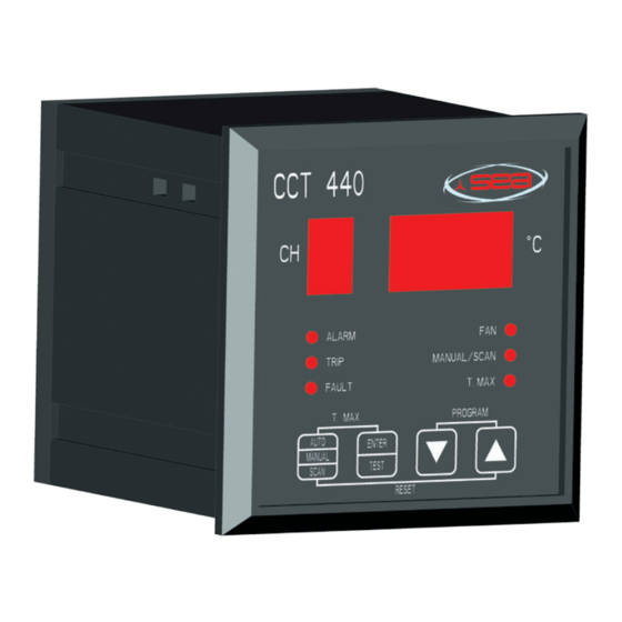
    Elektrische Anschlüsse Sämtliche Relais sind mit Umschaltkontakt. Sie können als Öffner oder Schließer gemäß der Anlagenlogik verwendet werden. Siehe den Schaltplan für CCT 440, CCT441 und CCT 442 das Ende dieses Handbuchs. SEA Spa - Società Elettromeccanica Arzignanese Seite 5 von 27...
  • Seite 50 04. Meldung Abgetrennt 12. Auswahl TASTE RAUF 13. Auswahl Maximaltemperatur (T.MAX), 05. Meldung Schaden ander Steuereinheit Tasten 9 und 10 14. Auswahl Programmierung (PROGRAM), 06. Meldung Belüftung eingeschaltet Tasten 11 und 12 SEA Spa - Società Elettromeccanica Arzignanese Seite 6 von 27...
  • Seite 51: Vorschriften

    5. Die Verbindungen müssen an geeignete Stellen, d.h. gegen elektromagnetische Störungen in der Frequenz (wie z.B. diejenigen die von Wechselrichtern oder ähnlichen Geräten erzeugt werden) installiert werden. SEA Spa - Società Elettromeccanica Arzignanese Seite 7 von 27...
  • Seite 52: Datenüberprüfung

    FAULT-Signal wird nicht automatisch quittiert, zumal auch wenn der Kanal erneut in die Parameter gelangt dieses nicht bedeutet, dass das Problem behoben wurde - das FAULT-Relais wird aktiv AKTIONEN - das entsprechende FAULT-LED blinkt SEA Spa - Società Elettromeccanica Arzignanese Seite 8 von 27...
  • Seite 53 Steuereinheit-Anzeige derjenige Wert, den die Steuereinheit ausgehend von dem Eingangssignal ableiten kann. Die Angabe von dem als defekt angenommen Kanal wird zum Schutz des Gerätes nicht ausgewertet. Durch Auswählen mit den SEA Spa - Società Elettromeccanica Arzignanese Seite 9 von 27...
  • Seite 54 Temperaturwert liegt über der für den MASSNAHME Alarm eingestellten Temperatur. - Störung oder Defekt an den Temperatursensoren (siehe Tabelle 1 “Maßnahmen Relais”) Überprüfen Sie sofort die Sensoren oder den FOLGEN Transformator. SEA Spa - Società Elettromeccanica Arzignanese Seite 10 von 27...
  • Seite 55 - Die Anlage wird sofort außer Betrieb gesetzt. Tabelle 1: Reaktionen Relais AKTIVE FEDEKTE SENSOR SENSOR FAULT ALARM TRIP NEIN REAKTIONEN DER RELAIS MIT NEIN NEIN DEFEKTEN NEIN SENSOREN NEIN NEIN NEIN SEA Spa - Società Elettromeccanica Arzignanese Seite 11 von 27...
  • Seite 56 Tasten AUTO/MANUAL/SCAN und PFEIL RAUF, um die Maximalwerte zu quittieren. (Auf der Bedientafel sind die beiden Tasten mit dem grafischen RESET-Zeichen verbunden) Um zu Beenden, muss die Taste AUTO/MANUAL/SCAN gedrückt werden SEA Spa - Società Elettromeccanica Arzignanese Seite 12 von 27...
  • Seite 57: Visualisierung Der Parameter

    Trägheit des zu schützenden Transformators sind. Programmierung CCT440, CCT441 und CCT442 RESET DER STEUEREINHEIT BESCHREIBUNG TASTEN Halten Sie die 4 Eingangstasten 5 Sekunden lang gedrückt, bis nicht alle Front-Meldungen aufleuchten. SEA Spa - Società Elettromeccanica Arzignanese Seite 13 von 27...
  • Seite 58: Steuereinheit

    DEUTSCH Die Steuereinheit initialisiert sich gemäß den SEA-Werkseinstellungen. An der Anzeige erscheint die Mitteilung: S rNN wo NN für die Revision- Nummer des installierten "Firmwares" darstellt. PROGRAMMIERUNG Schritt BESCHREIBUNG TASTEN Drücken Sie und halten Sie die 2 Eingangstasten PROGRAMMIER «TASTE RAUF»...
  • Seite 59 PARAMETER bestätigen Sie den gewünschten Wert mit der Taste «ENTER-TEST». CCT 440 – CCT 441 – CCT 442 “A” Alarmschwelle (140 °C SEA Standardeinstellung – siehe Kapitel 10) Frei einstellbar “t” Trennschwelle (150 °C SEA Standardeinstellung – siehe Kapitel 10) Frei einstellbar.
  • Seite 60 Die Anzahl der Stoppbits ist fest und entspricht 1 Das Datenanschlusskabel muss geschirmt und nur an einem Punkt geerdet sein. CCT 440 – CCT 441 – CCT 442 “C” Kugellagerschutz der Ventilatoren: 0: keine periodische Betätigung der Ventilatoren 1: periodische Betätigung der Ventilatoren einmal am Tag für 5 Minuten (SEA Standardeinstellung) 2: periodische Betätigung der Ventilatoren einmal die Woche für...
  • Seite 61 DEUTSCH d=6 gültig ist Werte in dem Bereich (1-3600 Sekunden) einstellbar SEA Standardeinstellung des Aggregats t=60 s Die Steuereinheit bestimmt die Ausführung der ausgewählten Funktionen. Am Bildschirm erscheint die Mitteilung: S rNN wo NN für die Revision-Nummer des installierten "Firmwares" darstellt.
  • Seite 62: Lesen Schreiben

    LESEN Alarm Kanal 1 -1000/+20000 SCHREIBEN LESEN Alarm Kanal 2 -1000/+20000 SCHREIBEN LESEN Alarm Kanal 3 -1000/+20000 SCHREIBEN LESEN Alarm Kanal 4 -1000/+20000 SCHREIBEN LESEN Trip Kanal 1 -1000/+20000 SCHREIBEN SEA Spa - Società Elettromeccanica Arzignanese Seite 18 von 27...
  • Seite 63 0 Relais Vor-Alarm nicht aktiv 1 Relais Vor-Alarm aktiv  Register 10 Status Relais Alarm: bit 1 0 Relais Alarm nicht aktiv 1 Relais Alarm aktiv  Register 10 Status Störung Relais: bit 2 SEA Spa - Società Elettromeccanica Arzignanese Seite 19 von 27...
  • Seite 64: Störung Relais Aktiv (Klemm-Buchse 15-13 Geschlossen) Normalzustand

    Register 1 bis 38 Format: 16 bit signed short (-32767 / +32767) Register 1 bis 38 haben Skalierungsfaktor 100 Unterstützte Modbus-Standardfunktionen: 03x Lesen Holding Register, 04x Lesen Eingangsregister 06x Schreiben Register, 16x Schreiben Multi-Register SEA Spa - Società Elettromeccanica Arzignanese Seite 20 von 27...
  • Seite 65: Überprüfung Der Relais

    Augenblick, das Austreten aus dem Menü TEST RELAIS. Aus Sicherheitsgründen wird in jedem Fall die für die Programmierung vergangene Verweilzeit überprüft. Wenn mehr als eine Minute Ruhezeit von Seiten des Bedieners vergangen SEA Spa - Società Elettromeccanica Arzignanese Seite 21 von 27...
  • Seite 66: Voreingegebene Standardwerte

    100-80°C 120-100°C 12 Gewährleistungsnormen Auf die Steuereinheiten CCT 440, CCT 441 und CCT 442 wird für einen Zeitraum von 1 Jahr ab Abnahmedatum, dass sich sowohl auf dem Etikett als auch in dem beiliegenden Handbuch befindet, Garantie gewährt. Die Garantie ist nur gültig, wenn festgestellt wurde, dass die Störungsursache auf...
  • Seite 67 MANUEL D’ INSTALLATION ET PROGRAMMATION CCT 440 - CCT 441 – CCT 442 FRANÇAIS Rev. 01 - 21/04/17 E-mail: info@seatrasformatori.it SEA Spa - Società Elettromeccanica Arzignanese sito: www.seatrasformatori.it...
  • Seite 68: Informations Générales Et De Sécurité

    Informations générales et de sécurité Le présent manuel est réservé exclusivement aux techniciens qualifiés et préparés soit du point de vue technique qu’en matière de sécurité .SEA ne sera pas responsable en cas d’opérations effectuées par des personnels ne possédant pas les qualifications requises.
  • Seite 69: Caractéristiques Techniques Du Produit

     La polarité des branchements peut être inversée , elle n’est pas fondamentale pour le système d’alimentation (voir boites de connexions 40 et 42).  Raccordements électriques sur boites de raccordement extractibles . Entrées Mesure et contrôle de la température avec capteurs Pt100 type SEA de -10 à +200°C Sorties Intensité Type de Type d’...
  • Seite 70  Échelle 4-20mA (-10°C 4mA - 200°C 20mA) Formule de transformation Iout = (T+10)/210*16 + 4 (courant en mA températures en °C)  Échelle 0-20mA (-10°C 0mA - 200°C 20mA) Formule de transformation Iout = (T+10)/210*20 (courant en mA températures en °C) SEA Spa - Società Elettromeccanica Arzignanese Page 4 de 26...
  • Seite 71: Raccordements Électriques

    Tous les relais sont à contact de passage. Ils peuvent être utilisés en ouverture ou en fermeture selon la logique de l’installation électrique. Voir schéma électrique pour CCT 440, CCT441 et CCT 442 à la fin de manuel . SEA Spa - Società Elettromeccanica Arzignanese...
  • Seite 72 12. Sélection TOUCHE VERS LE HAUT 05. voyant signalisation défaillance unité de 13. Sélection température maximum contrôle (T.MAX),touches 9 et 10 06. voyant signalisation mise en marche 14. Sélection programmation ventilation (PROGRAM),touches 11 et 12 SEA Spa - Società Elettromeccanica Arzignanese Page 6 de 26...
  • Seite 73 électromagnétiques comme par exemple celles produites par les onduleurs ou autres équipements semblables Les câbles des capteurs sono compensés par conséquent les capteurs ont trois SEA Spa - Società Elettromeccanica Arzignanese Page 7 de 26...
  • Seite 74 - le relais FAULT s’excite - Le voyant FAULT clignote ACTIONS  Clignotement rapide: affichage d’un canal défectueux SEA Spa - Società Elettromeccanica Arzignanese Page 8 de 26...
  • Seite 75 L’indication donnée par le canal considéré défectueux ne sera pas prise en considération pour la protection du dispositif. Dérouler avec les flèches pour vérifier l’état des autres canaux. CCT 442 SEA Spa - Società Elettromeccanica Arzignanese Page 9 de 26...
  • Seite 76 à la température paramétrée pour l’alarme - Panne ou anomalie des capteurs thermométriques (se reporter au tableau n.1 “ commutation relais ”) Effectuer immédiatement le contrôle des capteurs ou CONSÉQUENCE du transformateur SEA Spa - Società Elettromeccanica Arzignanese Page 10 de 26...
  • Seite 77 . - L’appareil est immédiatement mise hors service . Tableau 1: Commutation relais CAPTEU CAPTEURS PANNE ALARME TRIP RACTIF DEFECTUEUX COMMUTATION RELAIS AVEC CAPTEURS DÉFECTUEUX SEA Spa - Società Elettromeccanica Arzignanese Page 11 de 26...
  • Seite 78 2 secondes sur les touches AUTO/MANUAL/SCAN e FLÈCHE VERS LE HAUT . (Sur le panneau les deux touches sont reliées par ligne graphique de réinitialisation). Pour quitter appuyer sur la touche AUTO/MANUAL/SCAN SEA Spa - Società Elettromeccanica Arzignanese Page 12 de 26...
  • Seite 79: Affichage Des Paramètres

    L’unité de contrôle est réinitialisé sur les valeurs paramétrées dans l’usine SEA Sur l’écran apparait le message: S rNN où NN est le numéro de la SEA Spa - Società Elettromeccanica Arzignanese...
  • Seite 80 «ENTER- TEST». 1: mesure de trois capteurs (CH1 + CH2 + CH3) sans contrôle de la ventilation (Programme de default SEA) 2: mesure de trois capteurs (CH1 + CH2 + CH3) avec contrôle de la ventilation 3: mesure de quatre capteurs (CH1 + CH2 + CH3 + CH4) sans contrôle de la ventilation...
  • Seite 81 «ENTER- TEST». CCT 440 – CCT 441 – CCT 442 “A” Seuil de niveau d'alarme (140 °C par défaut SEA – voir chapitre 10) Réglable librement. “t” Seuil de niveau de déclenchement (150 °C par défaut SEA–...
  • Seite 82 “s” définit le type de standard à adopter S1 modalité 4-20 mA ( par défaut SEA de la centrale ) S2 modalité 0-20 mA “t”indique le temps de balayage en secondes valable seulement en modalité...
  • Seite 83 FRANÇAIS Par défaut SEA de la centrale t=60 s L’unité de contrôle configure les fonctions sélectionnées . Sur l’écran apparait le message: S rNN où NN est le numéro de la révision du “firmware” installé. Sélectionner CONTROLE DES affichage avec PARAMETRES «TOUCHE BAS»...
  • Seite 84 Fan hight level channel 1 -1000/+20000 READ WRITE Fan hight level channel 2 -1000/+20000 READ WRITE Fan hight level channel 1 -1000/+20000 READ WRITE Fan hight level channel 2 -1000/+20000 SEA Spa - Società Elettromeccanica Arzignanese Page 18 de 26...
  • Seite 85 Registers 1 to 38 format: 16 bit signed short (-32767 / +32767) Registers 1 to 38 have scale factor 100 Supported modbus standard functions: 03x Read holding register, 04x Read input register 06x Write register, 16x Write multi registers SEA Spa - Società Elettromeccanica Arzignanese Page 19 de 26...
  • Seite 86 Pour des raisons de sécurité le temps passé dans le menu nécessaire à la programmation est contrôlé . En cas d’inactivité de l’opérateur pendant plus d une minute l’unité revient en mode d’affichage automatique. SEA Spa - Società Elettromeccanica Arzignanese Page 20 de 26...
  • Seite 87: Normes De Garantie

    120-100°C 12 Normes de garantie Les unités de contrôle de la température CCT 440, CCT 441 et CCT 442 sont garanties pour une période d’ 1 an à compter de la date d’essai de mise en service indiquée soit sur l’étiquette que dans le manuel joint. La garantie est valable lorsqu’il a été...
  • Seite 89 MANUAL DE INSTALACIÓN Y PROGRAMACIÓN CCT 440 - CCT 441 – CCT 442 ESPAÑOL Rev. 01 - 21/04/17 Correo electrónico: info@seatrasformatori.it SEA Spa - Società Elettromeccanica Arzignanese Página web: www.seatrasformatori.it...
  • Seite 90: Información General Y De Seguridad

    Información general y de seguridad Este manual se dirige sólo a técnicos cualificados y preparados desde un punto de vista técnico y por lo que se refiere a la seguridad. SEA no es responsable por operaciones efectuadas por personal que no tiene la cualificación adecuada.
  • Seite 91  La polaridad de las conexiones puede ser invertida; no es determinante para el sistema de alimentación (véase terminales 40 y 42).  Conexiones eléctricas sobre regletas de bornes extraibles Entradas Detección y control de la temperatura con sensores Pt100 tipo SEA desde -10 hasta +200°C Salidas Tipo alimentación Tensión máxima Corriente máxima...
  • Seite 92  Escala 4-20mA (-10°C 4mA - 200°C 20mA) Fórmula de transformación lout = (T+10)/210*16 + 4 corriente en mA temperaturas en °C)  Escala 0-20mA (-10°C 0mA - 200°C 20mA) Fórmula de transformación lout = (T+10)/210*20 corriente en mA temperaturas en °C) SEA Spa - Società Elettromeccanica Arzignanese Página 4 de 27...
  • Seite 93: Conexiones Eléctricas

    Todos los relés son con contacto de conmutación. Se pueden utilizar para la apertura o el cierre según la lógica del sistema. Véase el esquema de conexión para CCT 440, CCT 441 y CCT 442 al final de este manual.
  • Seite 94 04. Señalización desenganche 12. Selección BOTÓN ARRIBA 13. Selección temperatura máxima (T.MAX), botones 9 05. Señalización avería centralita y 10 14. Selección programación (PROGRAM), botones 11 06. Señalización activación ventilador y 12 SEA Spa - Società Elettromeccanica Arzignanese Página 6 de 27...
  • Seite 95 Los cabes de las sondas están compensados, pues las sondas cuentan con tres conductores. SEA Spa - Società Elettromeccanica Arzignanese Página 7 de 27...
  • Seite 96 - El relativo led FAULT relampaguea  Luz intermitente veloz: visualización de un canal con ACCIONES avería  Luz intermitente lenta: señalización que por lo menos una sonda ahora no visualizada tiene avería. SEA Spa - Società Elettromeccanica Arzignanese Página 8 de 27...
  • Seite 97 Para parar la señal de FAULT, pulsar al mismo tiempo por SOLUCIÓN 5 segundos los botones AUTO/MANUAL/SCAN y FLECHA ARRIBA. (En el panel los dos botones están conectados SEA Spa - Società Elettromeccanica Arzignanese Página 9 de 27...
  • Seite 98 - Avería o anomalía a las sondas termométricas (véase tabla n.1 ”Intervenciones relé”) Seguir de inmediato con el control de las sondas o del CONSECUENCIAS transformador SEA Spa - Società Elettromeccanica Arzignanese Página 10 de 27...
  • Seite 99 - La señal de trip se enciende de manera continua hasta que la temperatura leída sobre por lo menos CONSECUENCIAS un canal sea superior a la temperatura de trip. En caso de sondas averiadas, el estado permanece. - El equipo se pone de inmediato fuera de servicio.
  • Seite 100 2 segundos los botones AUTO/MANUAL/SCAN y FLECHA ARRIBA. (En el panel los dos botones están conectados por una señal gráfica de reset). Para salir, pulsar el botón AUTO/MANUAL/SCAN SEA Spa - Società Elettromeccanica Arzignanese Página 12 de 27...
  • Seite 101 5 segundos hasta que todas las señales frontales no se encienden. La centralita se inicializa a los valores de fábrica SEA. En la pantalla aparece: S rNN donde NN es el número de revisión del “firmware” SEA Spa - Società Elettromeccanica Arzignanese...
  • Seite 102 5: menú avanzado para el control independiente de las alarmas y de los umbrales de ventilación para cada uno de los cuatro canales. Confirmar la selección pulsando el botón «ENTER-TEST» SEA Spa - Società Elettromeccanica Arzignanese Página 14 de 27...
  • Seite 103: Configuración De Los Parámetros

    «ENTER- TEST». CCT 440 – CCT 441 – CCT 442 “A” Umbral de nivel de alarmas (140 °C default SEA – ver capítulo 10) de configuración libre “t” Umbral de nivel de accionador (150 °C default SEA– ver capítulo 10)
  • Seite 104 2 d=3 salida fija temperatura canal 3 d=4 salida fija temperatura canal 4 d=5 salida canal más caliente (entre los activos) default SEA de la centralita d=6 salida en modaldiad escáner entre los canales activos “s”...
  • Seite 105 ESPAÑOL Valores configurables dentro del rango (1-3600 segundos) Default SEA de la centralita t=60 s La centralita configura la ejecución de las funciones seleccionadas. En la pantalla aparece: S rNN donde NN es el número de revisión del “firmware” instalado.
  • Seite 106 Alarma canal 4 -1000/+20000 LECTURA/ESCRITURA Trip canal 1 -1000/+20000 LECTURA/ESCRITURA Trip canal 2 -1000/+20000 LECTURA/ESCRITURA Trip canal 3 -1000/+20000 LECTURA/ESCRITURA Trip canal 4 -1000/+20000 Ventilador bajo nivel LECTURA/ESCRITURA -1000/+20000 canal 1 SEA Spa - Società Elettromeccanica Arzignanese Página 18 de 27...
  • Seite 107 0 Relé ventilador no activo 1 Relé ventilador activo  Registro 21 Estado canal desde 1 hasta 4: de bit 0 a bit 3 0 Canal inactivo 1 Canal habilitado SEA Spa - Società Elettromeccanica Arzignanese Página 19 de 27...
  • Seite 108 Registro de 1 a 38 tiene factor de escala 100 Funciones estándares modbus soportadas: 03x Lectura registro de la explotación, 04x Lectura registro de entrada 06x Escritura registro, 16x Escritura registros multiples SEA Spa - Società Elettromeccanica Arzignanese Página 20 de 27...
  • Seite 109 Por razones de seguridad, en todo caso se controla el tiempo de permanencia en el menú necesario para la programación. Después de un minuto de inactividad por parte del operador, la centralita vuelve en modalidad de visualización automática. SEA Spa - Società Elettromeccanica Arzignanese Página 21 de 27...
  • Seite 110: Valores Predefinidos

    1°C 12 Normas de garantía Las centralitas CCt 440, CCT 441 y CCT 442 están cubiertas por garantía por un período de 1 año desde la fecha de inspección indicada en la etiqueta y en el manual adjunto. La garantía se considera válida cuando se ha comprobado que las causas de la avería se deben a defectos de producción y errata...
  • Seite 111 CCT 440 CCT 440...
  • Seite 112 CCT 441 CCT 441 (con comunicazione Modbus RTU) CCT 441 (con comunicazione Modbus RTU) (with comunication Modbus RTU) 60: (GND) 60: (GND) 61: (RX/TX-) 61: (RX/TX-) 62: (RX/TX+) 62: (RX/TX+)
  • Seite 113 CCT 442 CCT 442 (con comunicazione Modbus RTU, 4/20mA o 0/20mA) CCT 442 (con comunicazione Modbus RTU, 4/20mA o 0/20mA) (with comunication Modbus RTU, 4/20mA o 0/20mA) 60: (GND) 60: (GND) 61: (RX/TX-) 61: (RX/TX-) 62: (RX/TX+) 62: (RX/TX+) 71: + 71: + 70: - 70: -...
  • Seite 116 S.E.A. Società Elettromeccanica Arzignanese S.p.A.– Società con Socio Unico, soggetta a direzione e coordinamento di ESSSE S.p.A. Sede Centrale, Legale e Amministrativa: Via Leonardo Da Vinci, 14 36071 Tezze di Arzignano (VI) – Italia Casella Postale 50 - Tel. +39 0444 482100 - Fax. +39 0444 482519 E-mail: info@seatrasformatori.it - Website: www.seatrasformatori.it...

Diese Anleitung auch für:

Cct 441Cct 442

Inhaltsverzeichnis