Inhaltsverzeichnis
Werbung
Quicklinks
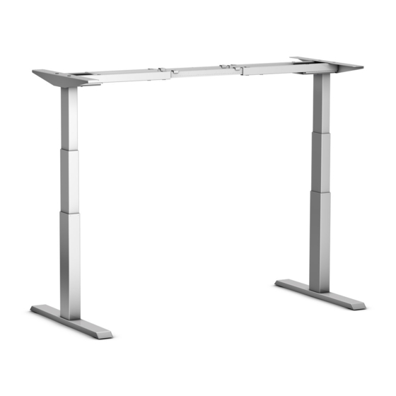
STEELFORCE PRO
SLS Highline SERIES 570 (60x90)/
670 (60x90)
Assembly Manual
Read this manual thoroughly and store in a safe place.
Montageanleitung
Bitte sorgfältig lesen und sicher aufbewahren.
Montagehandleiding
Lees deze handleiding aandachtig door en bewaar deze goed.
Manuel de montage
Veuillez lire attentivement ce manuel et le conserver dans un endroit sûr.
570 (60x90)
670 (60x90)
English
Deutsch
Nederlands
Français
Werbung
Inhaltsverzeichnis
Fehlerbehebung

Verwandte Anleitungen für Hettich STEELFORCE PRO SLS Highline 570 Serie

Inhaltszusammenfassung für Hettich STEELFORCE PRO SLS Highline 570 Serie
- Seite 1 STEELFORCE PRO English Deutsch Nederlands SLS Highline SERIES 570 (60x90)/ Français 670 (60x90) 570 (60x90) 670 (60x90) Assembly Manual Read this manual thoroughly and store in a safe place. Montageanleitung Bitte sorgfältig lesen und sicher aufbewahren. Montagehandleiding Lees deze handleiding aandachtig door en bewaar deze goed. Manuel de montage Veuillez lire attentivement ce manuel et le conserver dans un endroit sûr.
-
Seite 2: Inhaltsverzeichnis
English Content GENERAL ..................................6 Local value of the assembly/operating manual ....................6 Intended use ................................ 6 Improper use ................................ 6 Danger ................................. 6 Content box ..............................7-8 SAFETY INFORMATION ..............................9 Symbols/warnings ..............................9 Symbols used on the workstation frame ......................9 Maximum weight allowed on frame ......................... - Seite 3 Deutsch Inhaltsverzeichnis ALLGEMEINES ................................. 29 Stellenwert der Montage-/Bedienungsanleitung ..................... 29 Verwendungszweck ............................29 Unsachgemäße Verwendung ........................... 29 Gefahr .................................. 29 Lieferumfang ..............................30-31 SICHERHEITSHINWEISE ..............................32 Symbol– und Hinweiserklärungen ........................32 Verwendete Symbole am Tischgestell ......................32 Zulässiges Gesamtgewicht auf dem Tischgestell ..................... 32 Zulässiges Gesamtgewicht pro Säule ........................
- Seite 4 Nederlands Inhoudsopgave ALGEMEEN ................................... 52 Waarde van de montage- en gebruikershandleiding ................... 52 Beoogd gebruik ..............................52 Onjuist gebruik ..............................52 Gevaar ................................52 Inhoud verpakking ............................53-54 VEILIGHEIDSINSTRUCTIES ............................... 55 Verklaring van symbolen en instructies ......................55 Gebruikte symbolen op het frame ........................55 Maximaal toegestaan gewicht op het frame ....................
- Seite 5 Français Contenu GÉNÉRALITES ................................75 Valeur locale du manuel de montage/d'utilisation ..................75 Usage prévu ..............................75 Mauvaise utilisation ............................75 Danger ................................75 Contenu de la boîte ............................ 76-77 INFORMATIONS RELATIVES À LA SÉCURITÉ ......................... 78 Symboles/avertissements ..........................78 Symboles utilisés sur le cadre de poste de travail ..................
-
Seite 6: General
English 1 General 1.1 Local value of the assembly/Operating Manual The guiding principle for safe use and trouble-free operation of this workstation frame is knowledge of basic safety information and regulations. This assembly/operating manual contains the most important information needed for assembling and operating the workstation frame safely. This assembly/ operating manual, in particular the safety information contained herein, must be observed by any person building the frame and working on the finished surface. -
Seite 7: Content Box
English 1.5 Content Box Assembly requires 2 people! Items... -
Seite 8: Hardware Kit
English Hardware Kit M8x50 4.5x16 M6x16 4.5x20 4.5x20 M10x35 4x30 4.5x20 Tools Control Unit 6 : ControlForce 2 Pro : Input: 100-127Vac, 60Hz, 5A; Output: 24Vdc, 5A 220-240Vac, 50Hz, 2A; Output: 24Vdc, 5A... -
Seite 9: Safety Information
2 Safety Information 2.1 Symbols/Warnings The assembly/operating manual uses the following terms and signs to indicate dangers: This symbol indicates an immediate threatening situation for any person’s life or health. Failure to adhere to such information may have serious consequences for health, or could even result in life-threatening injury or death. -
Seite 10: Organizational Measures
English 2.5 Organizational measures • The workstation frame can best be assembled by two people. Turning the frame, once the work surface has been fitted, is a task in particular which requires two people! 2.6 Informal safety measures • Keep the assembly/operating manual in the place where the workstation frame is used at all times. -
Seite 11: Cleaning
English 2.13 Cleaning • Always unplug this workstation from the electrical outlet before cleaning. • Dust the workstation frame once a week with a dry cloth. • Clean the workstation frame with a damp cloth and a weak solution of cleaner once a fort- night. -
Seite 12: Cm Frame Set-Up Guide
English 3.2 120 cm Frame Set-Up Guide 120 cm Frame set-up - offset the inner crossbar to 110 cm and 130 cm as shown in diagram below. ... -
Seite 13: Pre-Assembly Of The Crossbars For Frame Set-Up For 130 Cm, 150 Cm And 170 Cm
English 3.3 Pre-assembly of the Crossbars for Frame set-up 130 cm, 150 cm and 170 cm Recommended Top Sizes Frame set-up Width / size table top Depth / size table top Table Top Thickness 130 cm 140 cm 80 cm 2.5 cm 150 cm 160 cm... -
Seite 14: Mounting The Feet
3.4 Mounting the Feet English Maximum Screw Torque : 10N-m 3.5 Mounting the Crossbar and Top Support Maximum Screw Torque : 12N-m... -
Seite 15: Mounting The Head Cover
English 3.6 Mounting the Head Cover 3.7 Adjustment of the Frame Width Adjust the frame into the desired width. Tighten the set screws on the crossbar Maximum Screw Torque : 10N-m with Allen key M5. -
Seite 16: Mounting The Spacer
3.8 Mounting the Spacers English English English 3.9 Mounting the Cable Clips ... -
Seite 17: Connecting The Electrical Components
English 3.10 Connecting the Electrical Components Keep in mind that the desk which you are assembling is height adjustable. The cables of the electrical components must be able to freely follow the movement of the desk. -
Seite 18: Mounting The Table Top
English 3.11 Mounting the table top 3.12 Mounting the power supply underneath the table top Total 4x Total 4x Total 4x/6x Total 12x... -
Seite 19: Mounting The Wire Clip
3.13 Mounting the Wire Clip English Bond loss cable together with cable tie. Mount the wire clips for cable. Peel off paper backing and stick to table top. Place wire into each wire clip. 3.14 Clearance around the wall or moving parts 25mm of the table top ... -
Seite 20: Frame Test Without Table Top
3.15 Frame test without table top English Please make sure that the workstation frame can move freely and correct at all times. In case you need to disconnect cables from the electrical components always be sure to disconnect power first. In case the height adjustment is not operating normally, stop using the workstation frame immediately and disconnect the power. -
Seite 21: Correct Position Of Seat
English 4 Correct position of seat Correct sitting posture Sitting incorrectly can lead to injuries at joints, bowstrings and muscles. In order to prevent this it is necessary to adjust your office chair and desk. Apart from the following advise you should always prevent an uncomfortable sitting posture. If you feel that the following advices leads you to an uncomfortable sitting posture simply adapt your needs. -
Seite 22: Technical Specifications
English 5 Technical Specification Assembly Manual version SLS-IM0117-4EN-DE-NL-FR-HT Year of construction 2022 Production country Malaysia System 1-step / 2 –step Material Steel, Aluminium and Plastic Stroke (max.) I. Steelforce Pro Highline 570 (60x90) SLS 490mm (19.3”) II. Steelforce Pro Highline 670 (60x90) SLS EN527 II. - Seite 23 English 5 Technical Specification (* General Tolerance = ± 10 mm) Steelforce Pro Highline 570 (60x90) SLS 110 - 170 cm 60 cm (43.3“-66.9“) (23.6“) 73.6 cm ((29“) Minimum Frame Height 70 cm (27.6“) Maximum Frame Height 119 cm (46.9“) Maximum Stroke 49 cm (19.3“) Frame Width...
- Seite 24 English 5 Technical Specification (* General Tolerance = ± 10 mm) Steelforce Pro Highline 670 (60x90) SLS 110 - 170 cm 60 cm (43.3“-66.9“) (23.6“) 73.6 cm (29“) Minimum Frame Height 62.5 cm (24.6“) Maximum Frame Height 128.5 cm (50.6“) Maximum Stroke 66 cm (26“) Frame Width...
-
Seite 25: Operation And Indicators
English 6 Operation and Indicators Observe the provisions of Section 2, Safety Information on page 7, in particular: Do not leave children unsupervised with the workstation frame. Children may be unaware of the dangers presented by the workstation frame. They would be in seri- ous danger of injuring themselves, possibly even with fatal consequences. -
Seite 26: Customer Service
8 Customer Service English Make sure you have the workstation frame information at hand when contacting the customer service. Retailer : 9 Manufacturer Actiforce International B.V. Het Steenland 20 3751 LA Bunschoten-Spakenburg The Netherlands +31 (0)33 4600120 www.actiforce.com info.holland@actiforce.com 10 Recycling 10.1 Taking the workstation out of active duty Pull the power plug out of the electricity socket. -
Seite 27: Ec-Declaration Of Conformity According To Machinery Directive 2006/42/Ec
English EC-Declaration of Conformity according to Machinery Directive 2006/42/EC, Annex II A We herewith confirm that the appliance as detailed below complies with the governing EU-directives (in particu- lar with those directives mentioned below) and bulk production will be manufactured accordingly. Article description: Electrical Height Adjustable Frame for Table Article number:... - Seite 28 English EC-Declaration of Conformity according to Machinery Directive 2006/42/EC, Annex II A We herewith confirm that the appliance as detailed below complies with the governing EU-directives (in particu- lar with those directives mentioned below) and bulk production will be manufactured accordingly. Article description: Electrical Height Adjustable Frame for Table Article number:...
-
Seite 29: Allgemeines
1 Allgemeines Deutsch 1.1 Stellenwert der Montage-/Bedienungsanleitung Das Grundprinzip für den sicheren Einsatz und den störungsfreien Betrieb dieses Arbeitsstationsgestells ist Kenntnis grundlegenden Sicherheitshinweise -vorschriften. Montage-/ Bedienungsanleitung beinhaltet die wichtigsten Informationen, die zur sicheren Montage und Be- dienung des Arbeitsstationgestells benötigt werden. Diese Montage-/Bedienungsanleitung, insbe- sondere die darin enthaltenen Sicherheitshinweise, sind von jeder Person zu beachten, die das Gestell aufbaut und an der fertigen Oberfläche arbeitet. -
Seite 30: Lieferumfang
Deutsch 1.5 Lieferumfang Montage mit 2 Personen! Teile oder oder oder... - Seite 31 Deutsch Beschlägebeutel M8x50 4.5x20 4.5x20 4.5x16 M6x16 M10x35 4x30 4.5x20 Werkzeuge * Steuerung (Netzgerät) 6 : ControlForce 2 Pro : Input : 100-127Vac, 60Hz, 5A; Output: 24Vdc, 5A 220-240Vac, 50Hz, 2A; Output: 24Vdc, 5A...
-
Seite 32: Sicherheitshinweise
Deutsch 2 Sicherheitshinweise 2.1 Symbol- und Hinweiserklärungen In der Betriebs- und Montageanleitung werden folgende Hinweise und Symbole für Gefährdungen ver- wendet: Dieses Symbol weist auf eine unmittelbar drohende Gefahr für das Leben und die Gesundheit von Personen hin. Das Nichtbeachten dieser Hinweise kann schwere gesundheitsschädliche Auswirkungen zum Beispiel lebensgefährliche Verletzugen. -
Seite 33: Organisatorische Maßnahmen
Deutsch 2.5 Organisatorische Maßnahmen • Montieren Sie das Tischgestell am besten mit zwei Personen. Speziell das Umdrehen des Gestells mit montier ter Tischplatte muss mit zwei Personen erfolgen! 2.6 Empfohlene Sicherheitsmaßnahmen • Bewahren Sie die Betriebs– und Montageanleitung ständig in der Nähe des Einsatzortes des Tischgestells auf. -
Seite 34: Reinigung
Deutsch 2.13 Reinigung • Ziehen Sie vor der Reinigung immer den Netzstecker aus der Steckdose. • Stauben Sie das Tischgestell mit einem trockenen Lappen einmal pro Woche ab. • Reinigen Sie das Tischgestell mit einem feuchten Tuch und mildem Reinigungsmittel alle 2 Wochen. 2.14 Restrisiken Das Tischgestell ist nach dem Stand der Technik und den anerkannten sicherheitstechnischen Regeln gebaut. -
Seite 35: Einstellung Der Traversen Auf 120 Cm
3.2 Einstellung der Traversen auf 120 cm Deutsch Einstellung der Traversen auf 120 cm - Verschieben Sie die innere Traverse wie im unten gezeigten Schaubild auf 110 cm und 130 cm. ... -
Seite 36: Vormontage Der Traverse Für 130 Cm, 150 Cm Und 170 Cm
3.3 Vormontage der Traversen für 130 cm, 150 cm und 170 cm Deutsch Empfohlene Tischplattenmaße Gestellbreite Tischplatten maße / Breite Tischplatten maße / Tiefe Tischplattenstärke 130 cm 140 cm 80 cm 2.5 cm 150 cm 160 cm 80 cm 2.5 cm 170 cm 180 cm 80 cm... -
Seite 37: Montage Der Kufen
Deutsch 3.4 Montage der Kufen Maximales Drehmoment : 10N-m 3.5 Montage der Traverse und Plattenträger Maximales Drehmoment : 12N-m... -
Seite 38: Montage Der Afdekkap
3.6 Montage der afdekkap Deutsch 3.7 Einstellen der Gestellbreite Schieben bzw. drücken Sie das Gestell in die gewünschte Breite. Ziehen Sie mit Hilfe des Maximales Drehmoment : 10N-m Sechskantschlüssel die Gewindestifte an der Traverse. -
Seite 39: Montage Der Abstandhalter
3.8 Montage des Abstandhalters Deutsch 3.9 Montage der Kabelhalterungen ... -
Seite 40: Anschließen Der Elektrischen Bauteile
Deutsch 3.10 Anschließen der elektrischen Bauteile Beachten Sie, dass der Schreibtisch, den Sie montieren, höhenverstellbar ist. Die Kabel der elektrischen Bauteile müssen der Bewegung des Schreibtisches ungestört folgen können. -
Seite 41: Montage Der Tischplatte
3.11 Montage der Tischplatte Deutsch 3.12 Montage des Netzteils unter der Tischplatte Total 4x Total 4x Total 4x/6x Total 12x... -
Seite 42: Montage Der Kabelclips
3.13 Montage der Kabelclips Deutsch Binden Sie überschüssiges Kabel mit einem Kabelbinder zusammen. Montieren Sie die Kabelclips. Legen Sie das Kabel durch die einzelnen Kabelclips. 3.14 Sicherheitsabstand zur Wand oder beweglichen Teilen von 25 mm um die Tischplatte 25mm 25mm Lassen Sie einen Sicherheitsabstand von 25 mm zwischen der Kante der Tischplatte und... -
Seite 43: Funktionstest Ohne Tischplatte
3.15 Funktionstest ohne Tischplatte Deutsch Please make sure that the workstation frame can move freely and correct at all times. In case you need to disconnect cables from the electrical components always be sure to disconnect power first. In case the height adjustment is not operating normally, stop using the workstation frame immediately and disconnect the power. -
Seite 44: Ergonomische Sitzeinstellung
Deutsch 4 Ergonomische Sitzeinstellung Richtige Sitzhaltung Falsches Sitzen kann zu Gelenk- und Sehnenschäden sowie Muskelschmerzen führen. Um dies zu vermeiden, müssen der Bürostuhl und der Schreibtisch richtig eingestellt werden. Zusätzlich zu den folgenden Empfehlungen sollten Sie unbequeme Sitzhaltungen stets vermeiden. Wenn Sie das Gefühl haben, dass die folgenden Empfehlungen bei Ihnen zu einer unangenehmen Sitzhaltung führen, passen Sie diese einfach an Ihre Bedürfnisse an. -
Seite 45: Technische Spezifikationen
Deutsch 5 Technische Spezifikationen Anleitungsversion SLS-IM0117-4EN-DE-NL-FR-HT Baujahr 2022 Ursprungsland Malaysia System 1-stufig / 2-stufig Material Stahl, Aluminium und Kunststoff Max. Hub I. Steelforce Pro Highline 570 (60x90) SLS 490mm (19.3”) II. Steelforce Pro Highline 670 (60x90) SLS EN527 II. 660mm (26”) Gestellbelastung (max.) 120 kg Eigengewicht... - Seite 46 Deutsch 5 Technische Spezifikationen (* Durchschnittliche Toleranzen = ± 10 mm) Steelforce Pro Highline 570 (60x90) SLS 110 - 170 cm 60 cm (43.3“-66.9“) (23.6“) 73.6 cm ((29“) Minimale Gestellhöhe 70 cm (27.6“) Maximale Gestellhöhe 119 cm (46.9“) Maximaler Hub 49 cm (19.3“) Gestellbreite 110-170 cm (43.3“-66.9“)
- Seite 47 Deutsch 5 Technische Spezifikationen (* Durchschnittliche Toleranzen = ± 10 mm) Steelforce Pro Highline 670 (60x90) SLS 110 - 170 cm 60 cm (43.3“-66.9“) (23.6“) 73.6 cm (29“) Minimale Gestellhöhe 62.5 cm (24.6“) Maximale Gestellhöhe 128.5 cm (50.6“) Maximaler Hub 66 cm (26“) Gestellbreite 110-170 cm (43.3“-66.9“)
-
Seite 48: Betriebshinweise
Deutsch 6 Betriebshinweise Beachten Sie die Bestimmungen im Abschnitt 2 Sicheheitshinweise auf Seite 24, insbesondere: Lassen Sie keine Kinder unbeaufsichtigt mit dem Tischgestell. Kinder können die von diesem Tischgestell ausgehenden Gefahren nicht einschätzen. Kinder können sich erheblich verletzen, bis hin zur Todesfolge. Weitere Vorkehrungen als Schutzmaßnah- me gegen die Benutzung durch Kinder sind nicht erforderlich. -
Seite 49: Kundendienst
8 Kundendienst Deutsch Bei Inanspruchnahme des Kundendienstes bitte stets den Tischgestelltyp angeben. Händler : 9 Hersteller Actiforce International B.V. Het Steenland 20 3751 LA Bunschoten-Spakenburg The Netherlands +31 (0)33 4600120 www.actiforce.com info.holland@actiforce.com 10 Entsorgung 10.1 Außerbetriebnahme des Tischgestells • Ziehen Sie den Netzstecker aus der Steckdose. 10.2 Tischgestell abbauen und ggf. -
Seite 50: Eg-Konformitätserklärung Nach Maschinenrichtlinie 2006/42/Eg
11 EG-Konformitätserklärung nach Maschinenrichtlinie 2006/42/EG, Deutsch Anhang II A Hiermit erklären wir, dass das nachfolgend bezeichnete Gerät den einschlägigen EG-Richtlinien (insbesondere den unten benannten) entspricht und die Serie entsprechend gefertigt wird. Artikelbezeichnung: Electrical Height Adjustable Frame for Table Artikelnummer: SLS66W15*008** Das erste Symbol "*"... - Seite 51 Deutsch 11 EG-Konformitätserklärung nach Maschinenrichtlinie 2006/42/EG, Anhang II A Hiermit erklären wir, dass das nachfolgend bezeichnete Gerät den einschlägigen EG-Richtlinien (insbesondere den unten benannten) entspricht und die Serie entsprechend gefertigt wird. Artikelbezeichnung: Electrical Height Adjustable Frame for Table Artikelnummer: SLS68W15*008** Das erste Symbol "*"...
-
Seite 52: Algemeen
Nederlands 1 Algemeen Waarde van de montage- en gebruikershandleiding Kennis van de basisveiligheidsinformatie en de voorschriften zijn de leidraad voor een veilige en probleemloze toepassing van deze werktafel. Deze montage- en gebruikershandleiding bevat de belangrijkste informatie die nodig is voor het veilig monteren en gebruiken van het tafelframe. Deze montage- en gebruikershandleiding, en in het bijzonder de veiligheidsinformatie, moet als leidraad dienen voor de persoon die het frame gaat monteren en in gebruik gaat nemen. -
Seite 53: Inhoud Verpakking
1.5 Inhoud verpakking Nederlands Onderdelen Monteer het frame met twee personen. - Seite 54 Nederlands Montage onderdelen set M8x50 4.5x20 4.5x20 4.5x16 M6x16 M10x35 4x30 4.5x20 Tools * Transformator 6 : ControlForce 2 Pro : Input: 100-127Vac, 60Hz, 5A; Output: 24Vdc, 5A 220-240Vac, 50Hz, 2A; Output: 24Vdc, 5A...
-
Seite 55: Veiligheidsinstructies
2 Veiligheidsinstructies Nederlands 2.1 Verklaring van symbolen en instructies In deze handleiding worden de volgende aanduidingen en symbolen voor gevaren gebruikt: Dit symbool betekent een rechtstreeks dreigend gevaar voor leven en gezondheid van personen. Het niet in acht nemen van deze instructies kan ernstige schade aan de gezondheid toebrengen en zelfs levensgevaarlijk lichamelijk letsel of de dood tot gevolg hebben. -
Seite 56: Organisatorische Maatregelen
Nederlands 2.5 Organisatorische maatregeln • Monteer het frame bij voorkeur met twee personen. Vooral het draaien van het frame met het gemonteerde werkblad moet door twee personen geschieden! 2.6 Informele veiligheidsmaatregelen • Bewaar de montage– en bedieningshandleiding altijd op de plaats waar het frame wordt ge- bruikt. -
Seite 57: Reiniging
Nederlands 2.13 Reiniging • Haal het werkstation altijd uit het stopcontact voordat u het schoonmaakt. • Verwijder eenmaal per week het stof van het frame met een droge doek. • Maak het frame om de twee weken schoon met een vochtige doek en een niet agressief schoonmaakmiddel. -
Seite 58: 120Cm Frame Instelling
Nederlands 3.2 120cm Frame instelling Frame instellen op 120cm - verschuif de binnenste crossbar tot 110 cm en 130cm zoals weergegeven in onderstaande afbeelding. ... -
Seite 59: Voormontage Van De Crossbar Voor 130 Cm, 150 Cm En 170 Cm
3.3 Voormontage van de crossbar voor 130 cm, 150 cm en 170 cm Nederlands Aanbevolen bladmaat Frame-breedte Werkblad breedte Werkblad diepte werkblad dikte 130 cm 140 cm 80 cm 2.5 cm 150 cm 160 cm 80 cm 2.5 cm 170 cm 180 cm 80 cm 2.5 cm... -
Seite 60: Montage Van De Voeten
3.4 Montage van de voeten Nederlands Maximale Schroefkoppel : 10N-m 3.5 Montage van de crossbar en bladdrager Maximale Schroefkoppel : 12N-m... -
Seite 61: Montage Van De Afdekkap
3.6 Montage van de afdekkap Nederlands 3.7 Instellen van de frame-breedte Stel het frame in op de gewenste breedte. Maximale Schroefkoppel : 10N-m Draai de set schroeven op de crossbar vast met de inbussleutel. -
Seite 62: Montage Van De Afstandhouders
3.8 Montage van de afstandhouders Nederlands 3.9 Montage van de kabelbinders ... -
Seite 63: Aansluiten Van De Elektrische Componenten
Nederlands 3.10 Aansluiten van de elektrische componenten Het is essentieel dat uw frame in hoogte verstelbaar is. De kabels van de elektrische componenten mogen tijdens een hoogteverstelling niet belemmerd worden. Let er hierbij op dat de maximale hoogteverstelling altijd mogelijk moet zijn! -
Seite 64: Montage Van De Handbediening
3.11 Montage van het werkblad Nederlands 3.12 Montage van de handbediening Total 4x Total 4x Total 4x/6x Total 12x... -
Seite 65: Montage Van De Kabelclips
Nederlands 3.13 Montage van de kabelclips Bind de losse kabels samen met de kabelbinders. Monteer de kabelclip. Plaas de kabel in de kabelclip. 3.14 Afstand van 25 mm tussen de muur of andere objecten en het werkblad 25mm 25mm Houd een minimum van 25 mm afstand tussen het werkblad en de muur of andere objecten. -
Seite 66: Frame Test Zonder Werklad
Nederlands 3.15 Frame test zonder werklad Let erop dat het frame te allen tijde correct en vrij kan bewegen Indien de kabel van de elektrische componenten moet worden losgekoppeld, dient u eerst de stroomtoevoer los te koppelen. Indien het frame niet naar behoren werkt, stop dan direct met werken aan het frame. -
Seite 67: Correcte Zitpositie
4 Correcte zitpositie Nederlands Correcte houding Een onjuiste houding kan schade aan gewrichten, pezen en spierpijn veroorzaken. Om dit te voorko- men, moet de bureaustoel en het bureau goed worden afgesteld. In aanvulling op de volgende aanbevelingen, moet een oncomfortabele zithouding worden voorkomen. Indien een van de vol- gende aanbevelingen leidt naar een voor u oncomfortabele houding, pas de bureaustoel en het bureau dan aan naar uw behoeften. -
Seite 68: Technische Specificaties
Nederlands 5 Technische specificaties Handleiding versie SLS-IM0117-4EN-DE-NL-FR-HT Datum 2022 Land van productie Maleisië Systeem Eentraps / Tweetraps Materiaal Staal, aluminium en plastic Slag (maximaal) I. Steelforce Pro Highline 570 (60x90) SLS 490mm (19.3”) II. Steelforce Pro Highline 670 (60x90) SLS EN527 II. - Seite 69 5 Technische specificaties Nederlands (* Gemiddelde tolerantie = ± 10 mm) Steelforce Pro Highline 570 (60x90) SLS 110 - 170 cm 60 cm (43.3“-66.9“) (23.6“) 73.6 cm ((29“) Minimale frame hoogte 70 cm (27.6“) Maximale frame hoogte 119 cm (46.9“) Maximale slag 49 cm (19.3“) Framebreedte...
- Seite 70 5 Technische specificaties Nederlands (* Gemiddelde tolerantie = ± 10 mm) Steelforce Pro Highline 670 (60x90) SLS 110 - 170 cm 60 cm (43.3“-66.9“) (23.6“) 73.6 cm (29“) Minimale frame hoogte 62.5 cm (24.6“) Maximale frame hoogte 128.5 cm (50.6“) Maximale slag 66 cm (26“) Framebreedte...
-
Seite 71: Bediening En Gebruiksaanwijzingen
Nederlands 6 Bediening en Gebruiksaanwijzingen Laat kinderen niet zonder toezicht het frame gebruiken. Kinderen zijn niet in staat de gevaren van het frame in te schatten. Ze lopen hierdoor groot risico op ernstig letsel, mogelijk zelfs met fatale gevolgen. Zorg er in ieder geval voor dat het frame niet verder versteld kan worden indien het toch door kinderen wordt gebruikt. -
Seite 72: Klantenservice
Nederlands 8 Klantenservice Houd de gegevens van het frame bij de hand wanneer u contact opneemt met uw dealer. Dealer: 9 Fabrikant Actiforce International B.V. Het Steenland 20 3751 LA Bunschoten-Spakenburg The Netherlands +31 (0)33 4600120 www.actiforce.com info.holland@actiforce.com 10 Recycling 10.1 Buitenbedrijfstelling van het frame •... -
Seite 73: Eu-Verklaring Van Overeenstemming Volgens Machinerichtlijn 2006/42/Eg, Bijlage Ii A
11 EU-Verklaring van overeenstemming volgens machinerichtlijn Nederlands 2006/42/EG, bijlage II A Hierbij verklaren wij dat het artikel dat hieronder wordt beschreven, voldoet aan de relevante EU-richtlijnen (in het bijzonder de hieronder vermelde) en dat de serie dienovereenkomstig is vervaardigd Artikelomschrijving: Electrical Height Adjustable Frame for Table Artikelnummer: SLS66W15*008**... - Seite 74 11 EU-Verklaring van overeenstemming volgens machinerichtlijn Nederlands 2006/42/EG, bijlage II A Hierbij verklaren wij dat het artikel dat hieronder wordt beschreven, voldoet aan de relevante EU-richtlijnen (in het bijzonder de hieronder vermelde) en dat de serie dienovereenkomstig is vervaardigd Artikelomschrijving: Electrical Height Adjustable Frame for Table Artikelnummer: SLS68W15*008**...
-
Seite 75: Généralites
Français 1 Généralités 1.1 Valeur locale du manuel de montage/d'utilisation Le principe directeur pour une utilisation sûre et un fonctionnement sans problème de ce cadre de poste de travail est la connaissance des informations et des règles de sécurité de base. Ce manuel de montage/d'utilisation contient les principales informations pour assembler et utiliser le cadre de poste de travail en toute sécurité. -
Seite 76: Contenu De La Boîte
Français 1.5 Contenu de la boîte Le montage nécessite la Articles présence de 2 personnes ! - Seite 77 Français Kit de matériel M8x50 4.5x16 4.5x20 4.5x20 M6x16 M10x35 4x30 4.5x20 Tools Outils Unité de commande 6: ControlForce 2 Pro : Entrée : 100-127Vac, 60Hz, 5A; Output: 24Vdc, 5A 220-240Vac, 50Hz, 2A; Output: 24Vdc, 5A...
-
Seite 78: Informations Relatives À La Sécurité
2 Informations relatives à la sécurité Français 2.1 Symboles/Avertissements Le manuel de montage/d’utilisation utilise les termes et les pictogrammes suivants pour indiquer des dangers : Ce symbole indique une situation de menace immédiate pour la vie ou la santé d'une personne. -
Seite 79: Mesures D'organisation
Français 2.5 Mesures d’organisation • Il est préférable de monter le cadre de poste de travail à deux personnes. Le retournement du cadre, une fois le plan de travail installé, est une tâche qui, en particulier, nécessite deux per- sonnes ! 2.6 Mesures de sécurité... -
Seite 80: Nettoyage
Français 2.13 Nettoyage • Débranchez toujours ce poste de travail de la prise électrique avant de le nettoy- • Dépoussiérez le cadre du poste de travail une fois par semaine avec un chiffon sec. • Nettoyez le cadre de poste de travail à l’aide d’un chiffon humide et d’un peu de détergent tous les quinze jours. -
Seite 81: Guide De Mise En Place Du Cadre 120 Cm
Français 3.2 Guide de mise en place du cadre 120 cm Mise en place du cadre 120 cm - Décalez la barre transversale intérieure de 110 cm et 130 cm comme indiqué sur le schéma ci-dessous. ... -
Seite 82: Prémontage Des Barres Transversales Pour La Mise En Place Du Cadre Pour 130 Cm, 150 Cm Et 170 Cm
Français 3.3 Prémontage des barres transversales pour la mise en place du ca- dre pour 130 cm, 150 cm et 170 cm Dimensions supérieures recommandées Mise en place du Largeur / dimension de Profondeur / dimen- Épaisseur de tablette cadre tablette sion de tablette 130 cm... -
Seite 83: Montage Des Pieds
Français 3.4 Montage des pieds couple de serrage maximal : 10N-m 3.5 Montage de la barre transversale et du support supérieur couple de serrage maximal : 12N-m... -
Seite 84: Montage Du Couvercle
Français 3.6 Montage du couvercle 3.7 Réglage de la largeur du cadre Réglez le cadre à la largeur désirée. Serrez les vis de réglage sur la barre couple de serrage maximal : 10N-m transversale avec la clé Allen M5. -
Seite 85: Montage Des Espaceurs
3.8 Montage des espaceurs Français 3.9 Montage des clips de câble ... -
Seite 86: Connexion Des Composants Électriques
Français 3.10 Connexion des composants électriques N'oubliez pas que le bureau que vous assemblez est réglable en hauteur. Les câbles des composants électriques doivent pouvoir suivre librement le mouvement du bureau. -
Seite 87: Montage Du Plateau
Français 3.11 Montage du plateau 3.12 Montage de l’alimentation électrique sous le plateau Total 4x Total 4x Total 4x/6x Total 12x... -
Seite 88: Montage Du Clip De Câble
3.13 Montage du clip de câble Français Reliez les câbles libres avec une attache de câble. Montez les clips pour le câble. Décollez le support papier et collez sur le plateau de la table. Placez le câble dans chaque clip de câble. 3.14 Espace autour du mur et des pièces mobiles à... -
Seite 89: Essai Du Cadre Sans Plateau
3.15 Essai du cadre sans plateau Français Veuillez vous assurer que le cadre de poste de travail se déplace toujours correctement et librement. Si vous devez débrancher les câbles des composants électriques, veillez toujours à couper l'alimentation électrique au préalable. Si le réglage de la hauteur ne fonctionne pas normalement, cessez immédiatement d'utiliser le cadre de poste de travail et débranchez l'alimentation. -
Seite 90: Position Correcte Du Siège
Français 4 Position correcte du siège Position assise correcte Une mauvaise position assise peut entraîner des blessures aux articulations, aux tendons et aux muscles. Pour l’éviter, il est nécessaire de régler votre siège et votre bureau. Outre le conseil suivant, vous devez toujours éviter une position assise inconfortable. Si vous pen- sez que les conseils suivants vous conduisent à... - Seite 91 Français Spécifications techniques Version du manuel de montage SLS-IM0117-4EN-DE-NL-FR-HT Année de construction 2022 Pays de production Malaisie Système 1 étape / 2 étapes Matériel Acier, Aluminium et Plastique Course (max.) 490mm (19.3”) I. Steelforce Pro Highline 570 (60x90) SLS II. 660mm (26”) II.
-
Seite 92: Spécifications Techniques
Français 5 Spécifications techniques = ± 10 mm) Tolérance générale Steelforce Pro Highline 570 (60x90) SLS 110 - 170 cm 60 cm (43.3“-66.9“) (23.6“) 73.6 cm ((29“) 70 cm (27.6“) Hauteur minimale du cadre 119 cm (46.9“) Hauteur maximale du cadre 49 cm (19.3“) Course maximale 110-170 cm (43.3“-66.9“) - Seite 93 Français 5 Spécifications techniques = ± 10 mm) Tolérance générale Steelforce Pro Highline 670 (60x90) SLS 110 - 170 cm 60 cm (43.3“-66.9“) (23.6“) 73.6 cm (29“) 62.5 cm (24.6“) Hauteur minimale du cadre 128.5 cm (50.6“) Hauteur maximale du cadre 66 cm (26“) Course maximale 110-170 cm (43.3“-66.9“)
-
Seite 94: Fonctionnements Et Indicateurs
Français 6 Fonctionnement et indicateurs Veuillez respecter les dispositions de la section 2, Informations relatives à la sécurité, page 7, en particulier : Ne laissez pas les enfants sans surveillance avec le cadre du poste de travail. Les en- fants peuvent ignorer les dangers que présente le cadre du poste de travail. Ils ris- queraient de se blesser gravement, voire de subir des conséquences mortelles. -
Seite 95: Service Clientèle
8 Service clientèle Français Assurez-vous d'avoir les informations sur le cadre de poste de travail à portée de main lorsque vous prenez contact avec le service clientèle. Revendeur : 9 Fabricant Actiforce International B.V. Het Steenland 20 3751 LA Bunschoten-Spakenburg Pays-Bas +31 (0)33 4600120 www.actiforce.com... -
Seite 96: Déclaration De Conformité Ce Au Sens De La Directive Machine 2006/42/Ce
11 Déclaration de conformité CE au sens de la directive machine Français 2006/42/CE, Annexe II A Nous confirmons par la présente que l'appareil décrit ci-dessous, est conforme aux directives européennes en vigueur (en particulier aux directives mentionnées ci-dessous) et que la série sera fabriquée en conséquence. Description de l’article : Electrical Height Adjustable Frame for Table Numéro d’article :... - Seite 97 11 Déclaration de conformité CE au sens de la directive machine Français 2006/42/CE, Annexe II A Nous confirmons par la présente que l'appareil, tel qu'il est décrit ci-dessous, est conforme aux directives eu- ropéennes en vigueur (en particulier aux directives mentionnées ci-dessous) et que la production en série sera Description de l’article : Electrical Height Adjustable Frame for Table Numéro d’article :...