Herunterladen Inhalt Inhalt Diese Seite drucken

Werbung

Verfügbare Sprachen

Verfügbare Sprachen

Heavy-Duty Camera Solutions
54
MBE5201-1
Bedienungs- und Montageanleitung
Installation and operating instructions
Notice de montage et d'utilisation
70
149
156
149
ZM-MBE5201-1

Werbung

Inhaltsverzeichnis
loading

Inhaltszusammenfassung für Motec Metek MBE5201-1

  • Seite 1 Heavy-Duty Camera Solutions ZM-MBE5201-1 MBE5201-1 Bedienungs- und Montageanleitung Installation and operating instructions Notice de montage et d'utilisation...
  • Seite 3: Inhaltsverzeichnis

    Umweltschutz ....................15 Allgemeine Informationen zur Bedienungsanleitung Vielen Dank für Ihr Vertrauen in AMETEK Motec Produkte. Wir entwickeln und fertigen unsere Produkte mit größter Sorgfalt. Sollten Sie Fragen zum Produkt, zur Inbetriebnahme oder Bedienung haben oder sollte das Produkt nicht Ihren Erwartungen entsprechen, sprechen Sie uns jederzeit gerne an.
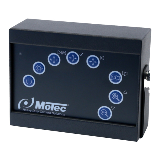
  • Seite 4: Produktbeschreibung

    Produktbeschreibung Das Motec Krankamerasystem der Serie 5201 ermöglicht die visuelle Über- wachung verschiedener Arbeitsbereiche am Kran direkt vom Arbeitsplatz des Kranführers aus. Die Bedienung der Motorzoomkamera erfolgt über die Bedien- einheit MBE5201-1. Ein komplettes Kamerasystem besteht mindestens aus fol- genden Komponenten:...
  • Seite 5: Konformitätserklärung

    Konformitätserklärung Als Inverkehrbringer innerhalb Europas haben wir für unsere Produkte gemäß den EU-Richtlinien und gesetzlichen Vorgaben eine Konformitätsbewertung nach den Anforderungen der jeweiligen „harmonisierten Normen“ durchgeführt. Sie finden die CE-Kennzeichnung auf dem Produkt sowie auf der begleitenden Produktdokumentation. Eine EG-Konformitätserklärung stellen wir Ihnen ger- ne auf Anfrage separat zur Verfügung.
  • Seite 6: Abmessungen Mbe5201-1

    Abmessungen MBE5201-1 Abmessungen in mm Lieferumfang Bezeichnung Matchcode Artikelnummer Bedieneinheit MBE5201-1 406 0176 009 Anschlusskabel MK59.1,5 403 0059 000 Bedienungsanleitung BA MBE5201-1 103 0000 205 Sicherheitsvorschriften Der elektrische Anschluss und die Inbetriebnahme dürfen nur von einer Fach- kraft nach den Angaben dieser Bedienungsanleitung erfolgen. Die Geräte dürfen nur in Betrieb gesetzt werden, wenn sich der Anwender über die Risiken und Gefahren, die aus der Benutzung des Gerätes resultieren, im Klaren ist.
  • Seite 7: Produktsicherheit

    Produktsicherheit Das Produkt entspricht dem Stand der Technik und den anerkannten sicher- heitstechnischen Regeln. Das Produkt darf nur in einwandfreiem Zustand und unter Beachtung der Betriebsanleitung betrieben werden. Zusätzliche Gefahren Überprüfen Sie das Kamerasystem vor der Verwendung auf erkennbare Mängel und beobachten Sie sein Verhalten im Betrieb bzgl.
  • Seite 8: Elektrischer Anschluss

    Die Steckverbindungen sind handfest zu verschrauben.   Abgriffe von Versorgungsspannungen dürfen nur an den vom jeweiligen Her-   steller dafür vorgesehenen Anschlusspunkten erfolgen. Abgriffe an Signallei- tungen führen i.d.R. zu Störungen. Elektrischer Anschluss Befestigen Sie das Bedienteil so, dass der Bediener es ohne Schwierigkeiten erreichen kann.
  • Seite 9 Video Schirm Anschluss C1: Anschlussstecker Motorzoomkamera MC5201-1 via Videoempfänger VE5201.24-1 und Videosender VS5201.24-1 Pin Bezeichnung Funktion VID_A Video Differenzsignal + VID_B Video Differenzsignal - VID_GND Video Schirm Versorgungsspannung +24 V DC 20025-00050 Masse CAN-H Motec CAN-Bus-Schnittstelle Motec CAN-L Motec CAN-Bus-Schnittstelle Motec...
  • Seite 10: Vorgehensweise Für Den Elektrischen Anschluss

    Anschluss C2: Anschlussstecker optionale Kompaktkamera Pin Bezeichnung Funktion Koax-Seele Video-Signal weiß Mirror schwarz Audio +12 VDC Koax-Schirm Video-GND Vorgehensweise für den elektrischen Anschluss 1) Schließen Sie das Versorgungskabel der Bedieneinheit und des Videosen- ders an die Versorgungsspannung (Dauerplus oder Zündungsplus) an. 2) Die Inbetriebnahme der Funkkomponenten wird im Kapitel 5.1 Inbetriebnah- me beschrieben.
  • Seite 11 Konfiguration: Bedie- Funktion nungsele- Ausgabe auf Monitor NORMAL MODE Service Mode ment Ein- bzw. Ausschalten des Service Mode (schaltet sich nach ca. 20 s automatisch aus) Aus- bzw. Einschalten Auto-Focus Auto-fokus der Motorzoom- AF OFF kamera (wenn ausge- schaltet) Manuelles Fokussieren Focus der Motorzoomkamera im Zustand von „AF OFF“...
  • Seite 12: Inbetriebnahme

    Inbetriebnahme Es ist sinnvoll vor dem Anschluss und Montage der Systemkomponenten zu- nächst Videosender (VE5201.24-1) und Videoempfänger (VE5201.24-1) auf- einander abzustimmen. Dieser Vorgang wird im folgenden TeachIn-Prozess genannt. Der TeachIn-Prozess kann aber auch nach erfolgreichem Anschluss und Montage am Kran selber erfolgen. Durch Betätigung der Ein-/Austaste wird das System ein- bzw.
  • Seite 13: Einstellungen

    Einstellungen Mit der Taste wird zwischen der Motorzoomkamera (C1) und einer optio- nalen Kamera (C2) (falls vorhanden) umgeschaltet. Ist keine 2. Kamera ange- schlossen, so ist der Bildschirm schwarz (kein Videosignal vorhanden). Wird die 2. Kamera (C2) z. B. als Rückfahrkamera benutzt, so kann das Bild horizontal gespiegelt werden.
  • Seite 14: Störungen

    äußere Beschaltung (Sicherung, Versorgungsspannung, Verkabelung, Kamera etc.) zu überprüfen. Kann die Nichtfunktion oder der Fehler eindeutig auf die Bedieneinheit MBE5201-1 zurückgeführt werden, so ist diese, zu- sammen mit einer kurzen Fehlerbeschreibung und einem RMA-Formular (www. motec-cameras.com/service/ruecksendung), an das Werk zurückzuschicken.
  • Seite 15: Wartung/Instandhaltung

    Die MBE5201-1 ist wartungsfrei. Reinigen Sie die Bedieneinheit nur mit einem weichen, eventuell angefeuchteten Tuch. Verwenden Sie zum Reinigen keine agressiven Reinigungsmittel. Die Produkte der Motec GmbH sind so konstruiert, dass sie eine lange Zeit problemlos und mit minimaler Wartung funktionieren.
  • Seite 17 Environmental protection ................29 General information about the operating instructions Thank you for your trust in AMETEK Motec products. We develop and produce our products with the greatest care. If you have questions about product, the initial set-up or the operation, or should the product not meet your expectations, please contact us and we will be happy to assist you.
  • Seite 18: Product Description

    Product description The Motec crane camera system series 5201 is intended for the visual monitor- ing of different work areas at the crane directly from the crane operator’s work- place. The motor zoom camera is operated via the MBE5201-1 operator control unit.
  • Seite 19: Declaration Of Conformity

    Declaration of Conformity As European distributor, we have followed the EU Guidelines and legal rules & regulations and have implemented a conformity assessment for all our pro- ducts. The assessment is compliant with the requirements of the “Harmonised Standards”. The CE label can be found on the product as well as the applicable product documentation.
  • Seite 20: Dimensions Mbe5201-1

    Dimensions MBE5201-1 Dimensions in mm Scope of delivery Description Match code Article number Operator control unit MBE5201-1 406 0176 008 Connection cable MK59.1,5 403 0059 000 Operating instructions BA MBE5201-1 103 0000 205 Safety instructions Only a qualified technician shall be permitted to install the electrical connection according to the information provided in the operating instructions.
  • Seite 21: Product Safety

    Product safety The product is based on state-of-the-art technology and meets all safety regu- lations. The product must be operated only in flawless condition and compliant with the operating manual. Additional risks Prior to using the camera system, check for detectable damage and observe its operation for any malfunctions.
  • Seite 22: Electrical Connection

    You may only tap into supply voltages at the dedicated connection points pro-   vided by the corresponding manufacturer for this purpose. Tapping into signal lines usually leads to malfunction. Electrical connection Install the control unit in a location which is accessible for the operator without difficulties.
  • Seite 23 VS5201.24-1 video transmitter Pin Description Function VID_A Video Difference signal + VID_B Video Difference signal - VID_GND Video shield Supply voltage +24 V DC 20025-00050 Ground CAN H Motec CAN bus interface Motec CAN L Motec CAN bus interface Motec...
  • Seite 24: Pin Description

    Connection C2: Connector for optional compact camera Pin Description Function Coax cable core Video signal white Mirror black Audio +12 VDC Coaxial shield Video GND How to proceed for electrical connection 1) Connect the supply cable of the operator control unit and of the video trans- mitter to the supply voltage (continuous positive or ignition positive).
  • Seite 25 Configuration: Control Function Monitor output unit NORMAL MODE Service Mode Switches the Service Mode on or off (switches off auto- matically after approx. 20 s) Switches the automatic Auto-Focus focus of the motor zoom AF OFF camera off or on (if switched off) Manual focussing of the Focus...
  • Seite 26: Initial Start-Up

    Initial start-up We recommend synchronising the video transmitter (VE5201.24-1) with the vi- deo receiver (VE5201.24-1) first, before connecting and installing system com- ponents. This process will be referred to as teach-in process in the following. The teach-in process can, however, also be performed after the successful connec- tion and installation at the crane.
  • Seite 27: Settings

    Settings If you push the button, the system toggles between the motor zoom camera (C1) and an optional camera (C2) (if available). If no 2nd camera is connected, the display is black (no video signal). If the 2nd camera (C2) is used, e. g. as a rear view camera, the image can be flipped horizontally.
  • Seite 28: Malfunctions

    If it is determined that the malfunction or error is clearly caused by the MBE5201-1 operator con- trol unit, the device including a short description of the malfunction and an RMA form (www.motec-cameras.com/service/ruecksendung) must be returned to the factory.
  • Seite 29: Maintenance/Repair

    Maintenance/repair The MBE5201-1 is maintenance-free. Use a soft and slightly damp cloth to clean the operator control unit. Do not use aggressive cleaning agents. All Motec GmbH products are designed to ensure trouble-free operation for a long period of time with minimum maintenance efforts. You can contribute to the long service life of equipment by cleaning the product properly and regularly.
  • Seite 31 à vos attentes, n’hésitez pas à nous contacter. Lisez attentivement la notice d’utilisation avant d’utiliser le produit. Elle doit être conservée pour pouvoir la consulter ultérieurement. Nos produits sont en con- tinuelle évolution. La société Motec GmbH se réserve le droit de modifier le produit sans préavis.
  • Seite 32: Description Du Produit

    Description du produit Le système de caméra de grue Motec de la série 5201 permet la surveillance visuelle de différentes zones de travail sur la grue directement depuis le poste de travail du grutier. La manipulation de la caméra à zoom motorisé se fait par le boîtier de commande MBE5201-1.
  • Seite 33: Déclaration De Conformité

    Déclaration de conformité En tant que distributeur au sein de l’Europe, nous avons effectué pour nos pro- duits une analyse de conformité conformément aux directives UE et aux dispo- sitions légales selon les exigences des « normes harmonisées » respectives. Vous trouverez le marquage CE sur le produit ainsi que sur la documentation produit jointe.
  • Seite 34: Dimensions Mbe5201-1

    Dimensions MBE5201-1 Dimensions en mm Contenu de livraison Désignation Matchcode Référence Boîtier de commande MBE5201-1 406 0176 008 Câble de connexion MK59.1,5 403 0059 000 Mode d’emploi BA MBE5201-1 103 0000 205 Prescriptions de sécurité Le raccordement électrique et la mise en service doivent être effectués unique- ment par un technicien qualifié...
  • Seite 35: Sécurité Du Produit

    Sécurité du produit Le produit correspond à l’état de la technique et aux règles de la sécurité tech- nique reconnues. Il doit être utilisé uniquement en parfait état de fonctionnement en respectant la notice technique. Dangers supplémentaires Avant utilisation, vérifiez la présence de défauts identifiables sur le système de caméras et observez le pendant qu’il fonctionne afin de détecter d’éventuels dysfonctionnements.
  • Seite 36: Raccordement Électrique

    Des capteurs de tensions d’alimentations ne doivent être utilisés que sur les   points de raccordement prévus à cet effet par le fabricant correspondant. Des capteurs sur des circuits de signalisation conduisent en général à des défauts. Raccordement électrique Fixez le dispositif de commande de manière à ce que l’opérateur puisse l’atteindre sans difficulté.
  • Seite 37 Prise de raccordement à la caméra à zoom motorisé MC5201-1 via le récepteur vidéo VE5201.24-1 et l’émetteur vidéo VS5201.24-1 Broche Désignation Fonction VID_A Vidéo signal différentiel + VID_B Vidéo signal différentiel - VID_GND Blindage vidéo Tension d'alimentation +24 V 20025-00050 Terre CAN-H Interface Motec Bus CAN Motec CAN-L Interface Motec Bus CAN Motec...
  • Seite 38: Procédure Pour Le Raccordement Électrique

    Câble de raccordement C2 : Prise de raccordement à la caméra compacte optionnelle Broche Désignation Fonction Âme coaxiale Signal vidéo blanc Miroir noir Audio rouge +12 VDC Blindage coaxial Vidéo GND Procédure pour le raccordement électrique 1) Branchez la câble d’alimentation du boîtier de commande et de l’émetteur vidéo sur la tension d’alimentation (plus permanent ou plus contact).
  • Seite 39 Configuration : Élément Fonction Affichage sur le de com- moniteur MODE NORMAL Mode service mande Mise en marche et arrêt du mode service (s’éteint automatiquement après env. 20 s) Arrêt et mise en marche de Auto-Focus l’auto focus de la caméra à AF OFF zoom motorisé...
  • Seite 40: Mise En Service

    Mise en service Il est important de synchroniser d’abord l’émetteur vidéo (VE5201.24-1) et le ré- cepteur vidéo (VE5201.24-1) l’un avec l’autre avant le raccordement et le monta- ge des composants du système. Cette opération est mentionnée dans le proces- sus TeachIn suivant. Le processus TeachIn peut également se faire lui-même après le raccordement réussi et le montage sur la grue.
  • Seite 41: Réglages

    coordonnés de manière à ce qu’à chaque démarrage du système, l’image vidéo apparaisse directement sur le moniteur. Réglages La touche permet la commutation entre la caméra à zoom motorisé (C1) et une caméra optionnelle (C2) (s’il y en a une). S’il n’y a pas de 2ème caméra branchée, alors l’écran est noir (il n’y a pas de signal vidéo).
  • Seite 42: Défauts

    (fusible, tension d’ali- mentation, câblage, écran etc.). Si le non-fonctionnement ou le défaut ne peut pas être reconnu clairement sur le boîtier de commande MBE5201-1, elle doit être envoyée à l’usine avec une courte description du défaut et un formulaire RMA (www.motec-cameras.com/service/ruecksendung).
  • Seite 43: Maintenance/Nettoyage

    Le MBE5201-1 ne nécessite pas de maintenance. Nettoyez le boîtier de com- mande uniquement avec un chiffon doux, éventuellement humide. N’utilisez pas de produits d’entretien agressifs pour le nettoyage. Les produits de Motec GmbH sont conçus de telle sorte qu’ils fonctionnent longtemps sans problème avec un entretien minimal.
  • Seite 44 Motec GmbH Oberweyerer Straße 21 65589 Hadamar GERMANY Phone +49 6433-9145 0 motec.info@ametek.com www.motec-cameras.com Copyright © 2018 by Motec GmbH | Art. No. 103 0000 205 BA-MBE5201-1 | 08/2018 | Subject to change without notice.

Inhaltsverzeichnis