Herunterladen Inhalt Inhalt Diese Seite drucken

Axis Communications T99A12 Installationsanleitung

Positioning unit 24 v ac/dc
Inhaltsverzeichnis

Werbung

Verfügbare Sprachen
  • DE

Verfügbare Sprachen

  • DEUTSCH, seite 55
AXIS T99A12 Positioning Unit 24 V AC/DC
Installation Guide

Werbung

Inhaltsverzeichnis
loading

Inhaltszusammenfassung für Axis Communications T99A12

  • Seite 1 AXIS T99A12 Positioning Unit 24 V AC/DC Installation Guide...
  • Seite 3 English Français Deutsch Italiano Español 日本語 中文: 简体中文...
  • Seite 4 See to take adequate measures. Disposal and recycling on page 5. A copy of the original declaration of conformity Japan may be obtained from Axis Communications AB. See Contact information on page 5.
  • Seite 5 Safety Extra Low Voltage (SELV) according to clause 2.2 of IEC/EN/UL 60950-1 Contact information • Class 1 electrical energy source (ES1) according Axis Communications AB to IEC/EN/UL 62368-1 Gränden 1 We recommend the use of Axis power supply DIN PS24 223 69 Lund 480 W.
  • Seite 7: Safety Information

    AXIS T99A12 Positioning Unit 24 V AC/DC Safety information Hazard levels DANGER Indicates a hazardous situation which, if not avoided, will result in death or serious injury. WARNING Indicates a hazardous situation which, if not avoided, could result in death or serious injury.
  • Seite 8 AXIS T99A12 Positioning Unit 24 V AC/DC • Use only applicable tools when installing the Axis product. Using excessive force with power tools could cause damage to the product. • Do not use chemicals, caustic agents, or aerosol cleaners. • Use a clean cloth dampened with pure water for cleaning.
  • Seite 9: Package Contents

    AXIS T99A12 Positioning Unit 24 V AC/DC Package contents • Positioning unit • Power connector • I/O connector • Torx® bit T20 (long) and T30...
  • Seite 10: Product Overview

    AXIS T99A12 Positioning Unit 24 V AC/DC Product overview Positioning unit (tilt) Positioning unit (pan) Base unit Camera (not included)
  • Seite 11 AXIS T99A12 Positioning Unit 24 V AC/DC Illuminator cables (not to be used) Camera power cable Camera network cable Camera serial interface cable Input power connector I/O connector RJ45 connector SFP slot for SFP module (SFP module not included)
  • Seite 12: How To Install The Product

    AXIS T99A12 Positioning Unit 24 V AC/DC How to install the product DANGER Risk of electric shock. All cables shall be de-energized before installing the product. CAUTION The electrical connections and conduit installations shall be made by a certified electrician and in compliance with local regulations.
  • Seite 13 AXIS T99A12 Positioning Unit 24 V AC/DC NO TICE TICE TICE Do not use sharp tools when you remove the transparent base unit cover. 4. Remove the transparent base unit cover. Conduit cover clip Conduit cover...
  • Seite 14: Route The Cables

    AXIS T99A12 Positioning Unit 24 V AC/DC Screw hole (x4) 5. For conduit installations only: remove the two conduit cover clips followed by the conduit cover. 6. Attach the base unit to the mounting surface with appropriate fasteners in the four screw holes.
  • Seite 15 AXIS T99A12 Positioning Unit 24 V AC/DC 1. Install the optional conduit adapters (not included). 2. Connect the grounding braid to the grounding screw. 3. Insert the power cable, I/O cable and network cable through the hole in the base unit as shown in the illustration above.
  • Seite 16 AXIS T99A12 Positioning Unit 24 V AC/DC Power cable (not included) I/O cable (optional, not included) Network cable (not included) Cable gasket Transparent base unit cover 8. Fit cable gaskets on the cables. See Cable thickness on page 28. 9. Insert the power, I/O and network cables including the cable gaskets through the holes in the transparent base unit cover and arrange the cables as shown in the illustration above.
  • Seite 17 AXIS T99A12 Positioning Unit 24 V AC/DC 10. Place the transparent base unit cover on the base unit and fit the cable gaskets inside the holes. I/O connector Power connector O-ring NO TICE TICE TICE To not accidentally disconnect the unit from power if the cable is pulled, let the protective grounding wire be about 10 mm (0.4 in) longer than the other two wires (in the power...
  • Seite 18 AXIS T99A12 Positioning Unit 24 V AC/DC 13. Place the positioning unit on the base unit. Make sure that the arrows on the two units are aligned. 14. Turn the positioning unit clockwise back to its original position and tighten the four base unit screws (torque 3.0 Nm).
  • Seite 19: Install The Network Link

    AXIS T99A12 Positioning Unit 24 V AC/DC Install the network link You can choose between different options when you install the network link: • A: via an optical fiber or RJ45 cable connected to the SFP module (with a respective connector) in the SFP slot.
  • Seite 20 AXIS T99A12 Positioning Unit 24 V AC/DC 1. Remove the cable gaskets from the camera’s bottom cover. 2. Insert the network/power/serial interface cable trough the holes in the bottom cover. 3. Fit the bottom cover on the positioning unit.
  • Seite 21 AXIS T99A12 Positioning Unit 24 V AC/DC 4. Tilt the bottom cover backward to its end position and tighten the two front screws of the positioning unit (T20, torque 3.0 Nm).
  • Seite 22 AXIS T99A12 Positioning Unit 24 V AC/DC 5. Tilt the bottom cover forward to its end position and tighten the two rear screws of the positioning unit (T20, torque 3.0 Nm). 6. Connect the camera network, serial interface and power cables according to the camera’s installation guide.
  • Seite 23: Connect The Cables

    AXIS T99A12 Positioning Unit 24 V AC/DC Connect the cables 1. Loosen the four lid screws (T20) and remove the lid. Input power connector I/O connector RJ45 connector SFP slot for SFP module (SFP module not included) 2. Connect the network (optical fibre and/or RJ45), I/O and power cables. For more information on different network connectivity options, see Install the network link on page 18.
  • Seite 24: Install The Ptz Driver

    AXIS T99A12 Positioning Unit 24 V AC/DC Install the PTZ driver This product supports several devices. For a complete list of supported devices, see axis.com 1. Go to the camera’s webpage. 2. In the installation wizard, go to Select a PTZ mode and select PTZ driver from the drop-down list.
  • Seite 25: Network Connector

    AXIS T99A12 Positioning Unit 24 V AC/DC Specifications Connectors Network connector RJ45 Ethernet connector. SFP connector. NO TICE TICE TICE The product shall be connected using a shielded network cable (STP) or an optical fiber cable. All cables connecting the product to the network shall be intended for their specific use.
  • Seite 26: Power Connector

    AXIS T99A12 Positioning Unit 24 V AC/DC 3– Configurable Digital input – Connect to pin 1 to activate, or 0 to max 30 V DC (Input or leave floating (unconnected) to deactivate. Output) 0 to max 30 V DC, Digital output – Internally connected to pin 1 (DC...
  • Seite 27 AXIS T99A12 Positioning Unit 24 V AC/DC This table is only valid for the 24 V AC and the 24 V DC power connectors. Position 24 V AC 24 V DC Protective earth Protective earth 24 V AC Phase + 24 V...
  • Seite 28 AXIS T99A12 Positioning Unit 24 V AC/DC RS485/RS422 connector Two 2-pin terminal blocks for RS485/RS422 serial interface used to control auxiliary equipment such as pan-tilt devices. The serial port can be configured to support: • Two-wire RS485 half duplex •...
  • Seite 29 AXIS T99A12 Positioning Unit 24 V AC/DC Camera serial interface cable Cable color Specification White RS485A Green RS485B Camera power cable Cable color Specification + 24 V DC Black...
  • Seite 31: Informations Sur La Sécurité

    AXIS T99A12 Positioning Unit 24 V AC/DC Informations sur la sécurité Niveaux de risques DANGER Indique une situation dangereuse qui, si elle n'est pas évitée, entraînera le décès ou des blessures graves. AVERTISSEMENT Indique une situation dangereuse qui, si elle n'est pas évitée, pourrait entraîner le décès ou des blessures graves.
  • Seite 32: Transport

    AXIS T99A12 Positioning Unit 24 V AC/DC • Ne pas exposer ce produit Axis aux chocs ou aux fortes pressions. • Ne pas installer ce produit sur des poteaux, supports, surfaces ou murs instables. • Utiliser uniquement des outils recommandés pour l'installation de l'appareil Axis.
  • Seite 33: Contenu De L'emballage

    AXIS T99A12 Positioning Unit 24 V AC/DC Contenu de l’emballage • Unité de positionnement • Connecteur d'alimentation • Connecteur d'E/S • Embout Torx® T20 (long) et T30...
  • Seite 34 AXIS T99A12 Positioning Unit 24 V AC/DC Product overview Unité de positionnement (inclinaison) Unité de positionnement (panoramique) Opercule Unité de base Caméra (non incluse)
  • Seite 35 AXIS T99A12 Positioning Unit 24 V AC/DC Câbles de projecteur (ne doivent pas être utilisés) Câble électrique de la caméra Câble réseau de la caméra Câble interface série de la caméra Connecteur d'alimentation d'entrée Connecteur d'E/S Connecteur RJ45 Emplacement SFP pour module SFP (module SFP non inclus)
  • Seite 36: Comment Installer Le Produit

    AXIS T99A12 Positioning Unit 24 V AC/DC Comment installer le produit DANGER Risque de choc électrique. Tous les câbles doivent être hors tension avant d'installer le produit. ATTENTION Les connexions électriques et les installations de conduites doivent être effectuées par un électricien certifié...
  • Seite 37 AXIS T99A12 Positioning Unit 24 V AC/DC A A A VIS N'utilisez pas d'outils tranchants lorsque vous déposez le couvercle transparent de l'unité de base. 4. Déposez le couvercle transparent de l'unité de base. Clip du cache de conduit...
  • Seite 38: Acheminement Des Câbles

    AXIS T99A12 Positioning Unit 24 V AC/DC Cache de conduit Trou de vis (x4) 5. Pour des installations de conduit uniquement : déposez les deux clips du cache de conduit suivis par le cache du conduit. 6. Fixez l'unité de base à la surface de montage avec les éléments de fixation appropriés dans les quatre trous de vis.
  • Seite 39 AXIS T99A12 Positioning Unit 24 V AC/DC passage du câble inférieur 1. Installez les adaptateurs de conduit en option (non fournis). 2. Reliez la tresse de terre à la vis de mise à la terre. 3. Insérez le câble d'alimentation, le câble d'E/S et le câble réseau à travers l'orifice de l'unité...
  • Seite 40 AXIS T99A12 Positioning Unit 24 V AC/DC Câble d'alimentation (non inclus) Câble E/S (en option, non fourni) Câble réseau (non inclus) Joint de câble Couvercle transparent de l'unité de base 8. Placez les joints sur les câbles. Cf. Épaisseur du câble à la page 52.
  • Seite 41 AXIS T99A12 Positioning Unit 24 V AC/DC d'informations sur les différentes options de connectivité réseau, consultez Installation de la liaison réseau à la page 42. 10. Placez le couvercle transparent de l'unité de base sur celle-ci et placez les joints dans les orifices.
  • Seite 42 AXIS T99A12 Positioning Unit 24 V AC/DC A A A VIS Assurez-vous que les joints toriques sont correctement fixés autour du couvercle transparent de l'unité de base. 13. Placez l'unité de positionnement sur l'unité de base. Assurez-vous que les flèches des deux unités sont alignées.
  • Seite 43: Installation De La Liaison Réseau

    AXIS T99A12 Positioning Unit 24 V AC/DC Installation de la liaison réseau Vous pouvez choisir entre plusieurs options lorsque vous installez la liaison réseau : • A : via un câble à fibre optique ou un câble RJ45 raccordé au module SFP (avec connecteur correspondant) sur l'emplacement SFP.
  • Seite 44 AXIS T99A12 Positioning Unit 24 V AC/DC 1. Retirez les joints de câble du couvercle inférieur de la caméra. 2. Insérez le câble d'interface réseau/alimentation/série à travers les trous du couvercle inférieur. 3. Montez le couvercle inférieur sur l'unité de positionnement.
  • Seite 45 AXIS T99A12 Positioning Unit 24 V AC/DC 4. Inclinez le couvercle inférieur vers l'arrière jusqu'à sa position finale et serrez les deux vis avant de l'unité de positionnement (T20, couple 3 Nm).
  • Seite 46 AXIS T99A12 Positioning Unit 24 V AC/DC 5. Inclinez le couvercle inférieur vers sa position finale et serrez les deux vis arrière de l'unité de positionnement (T20, couple 3 Nm). 6. Branchez les câbles réseau, interface série et d'alimentation de la caméra conformément au guide d'installation de la caméra.
  • Seite 47: Branchez Les Câbles

    AXIS T99A12 Positioning Unit 24 V AC/DC Branchez les câbles 1. Desserrez les quatre vis du couvercle (T20) et retirez le couvercle. Connecteur d'alimentation d'entrée Connecteur E/S Connecteur RJ45 Emplacement SFP pour module SFP (module SFP non inclus) 2. Branchez le câble réseau (fibre optique et/ou RJ45), E/S et d'alimentation. Pour plus d'informations sur les différentes options de connectivité...
  • Seite 48: Installation Du Pilote Ptz

    AXIS T99A12 Positioning Unit 24 V AC/DC 5. Mettez le produit sous tension. Installation du pilote PTZ Cet produit est compatible avec plusieurs appareils. Pour connaître la liste complète des appareils pris en charge, consultez le site axis.com. 1. Accédez à la page Web de la caméra.
  • Seite 49: Connecteur Réseau

    AXIS T99A12 Positioning Unit 24 V AC/DC Specifications Connecteurs Connecteur réseau Connecteur Ethernet RJ45. Connecteur SFP. A A A VIS Le produit doit être connecté à l'aide d'un câble réseau blindé (STP) ou d'un câble à fibres optiques. Tous les câbles reliant le produit au commutateur réseau doivent être destinés à...
  • Seite 50: Connecteur D'alimentation

    AXIS T99A12 Positioning Unit 24 V AC/DC 3– Configurable Entrée numérique - Connectez-vous à la broche 1 0 à 30 V CC max. (entrée ou pour activer ou laisser non connecté pour sortie) désactiver. Sortie numérique – Connexion interne à la 0 à...
  • Seite 51 AXIS T99A12 Positioning Unit 24 V AC/DC Ce tableau concerne uniquement les connecteurs d'alimentation 24 V CA et 24 V CC. Position 24 V CA 24 V CC Terre de protection Terre de protection Phase 24 V CA + 24 V 24 V CA Neutre Non connecté...
  • Seite 52 AXIS T99A12 Positioning Unit 24 V AC/DC Connecteur RS485/RS422 Deux blocs terminaux à 2 broches pour l’interface série RS485/RS422 utilisée pour commander les équipements auxiliaires, tels que les dispositifs panoramique/inclinaison. Le port série peut être configuré pour la prise en charge de : •...
  • Seite 53 AXIS T99A12 Positioning Unit 24 V AC/DC Pour plus d'informations sur les accessoires, tels que les joints de câble et les presse-étoupes adaptés à d'autres zones de câble, consultez www.axis.com Câble interface série de la caméra Couleur du câble Caractéristiques techniques...
  • Seite 55: Sicherheitsinformationen

    AXIS T99A12 Positioning Unit 24 V AC/DC Sicherheitsinformationen Gefährdungsstufen GEFAHR Weist auf eine gefährliche Situation hin, welche, falls nicht verhindert, zu Tod oder schweren Verletzungen führen kann. WARNUNG Weist auf eine gefährliche Situation hin, welche, falls nicht verhindert, zu Tod oder schweren Verletzungen führen kann.
  • Seite 56 AXIS T99A12 Positioning Unit 24 V AC/DC • Lagern Sie das Axis Produkt in einer trockenen und belüfteten Umgebung. • Das Axis Produkt weder Stößen noch starkem Druck aussetzen. • Das Produkt nicht an instabilen Masten, Halterungen, Oberflächen oder Wänden anbringen.
  • Seite 57: Lieferumfang

    AXIS T99A12 Positioning Unit 24 V AC/DC Lieferumfang • Positionierungseinheit • Stromanschluss • E/A-Anschluss • Torx-Bit® T20 (lang) und T30...
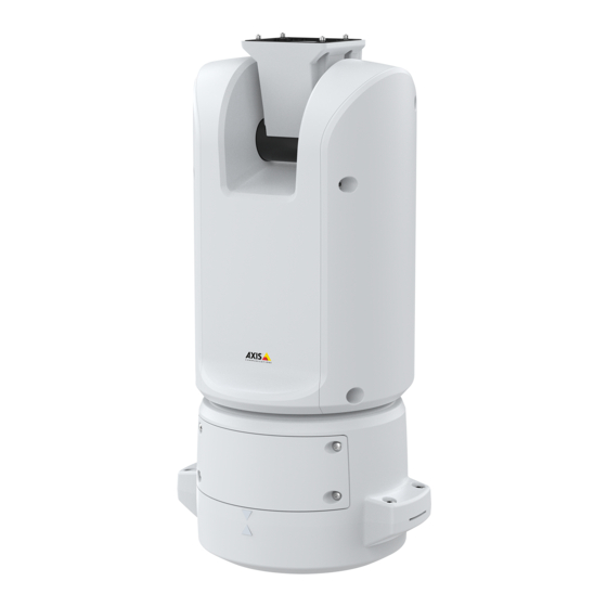
  • Seite 58: Produktübersicht

    AXIS T99A12 Positioning Unit 24 V AC/DC Produktübersicht Positionierungseinheit (Neigen) Positionierungseinheit (Schwenken) Deckel Basiseinheit Kamera (nicht im Lieferumfang enthalten)
  • Seite 59 AXIS T99A12 Positioning Unit 24 V AC/DC Strahlerkabel (nicht zu verwenden) Stromversorgungskabel der Kamera Netzwerk-Kabel der Kamera Serielles Schnittstellenkabel der Kamera Stromversorgungsanschluss Eingang E/A-Anschluss RJ-45-Anschluss SFP-Einschub für SFP-Module (SFP-Modul nicht enthalten)
  • Seite 60: Installieren Des Produkts

    AXIS T99A12 Positioning Unit 24 V AC/DC Installieren des Produkts GEFAHR Stromschlaggefahr Vor der Installation oder Wartung des Produkts müssen alle Kabel von der Stromversorgung abgeklemmt werden. VORSICHT Die Installation der elektrischen Anschlüsse und Kabelkanäle darf nur von einem zugelassenen Elektriker in Übereinstimmung mit den geltenden Bestimmungen vorgenommen werden.
  • Seite 61 AXIS T99A12 Positioning Unit 24 V AC/DC HINWEIS HINWEIS HINWEIS Beim Entfernen der transparenten Abdeckung der Gerätebasis keine spitzen Werkzeuge verwenden. 4. Die transparente Abdeckung der Gerätebasis entfernen. Klammer der Kabelführung...
  • Seite 62: Die Kabel Verlegen

    AXIS T99A12 Positioning Unit 24 V AC/DC Abdeckung der Kabelführung Schraubenbohrung (4 x) 5. Nur bei Installationen über die Kabelführung: Zuerst die beiden Klammern der Kabelführung und anschließend die Abdeckung der Kabelführung entfernen. 6. Die Gerätebasis mit geeigneten Befestigungselementen für die vier Schraubenbohrungen an der Befestigungsfläche anbringen.
  • Seite 63 AXIS T99A12 Positioning Unit 24 V AC/DC Kabelöffnung unten 1. Die optionalen Kabelführungsadapter installieren (nicht im Lieferumfang enthalten). 2. Das Erdungskabel mit der Erdungsschraube befestigen. 3. Die Kabel für Stromversorgung, Netzwerk und E/A einschließlich der Kabelverschraubungen wie in der Abbildung oben durch die Öffnung des Basisgeräts führen.
  • Seite 64 AXIS T99A12 Positioning Unit 24 V AC/DC Stromversorgungskabel (nicht im Lieferumfang enthalten) E/A-Kabel (optional, nicht im Lieferumfang enthalten) Netzwerk-Kabel (nicht im Lieferumfang enthalten) Kabeldichtung Transparente Abdeckung der Gerätebasis 8. Die Kabeldichtungen auf die Kabel schieben. Siehe Kabelstärke auf Seite 76.
  • Seite 65 AXIS T99A12 Positioning Unit 24 V AC/DC Weitere Informationen zu den verschiedenen Anschlussoptionen an das Netzwerk, siehe Einrichten der Netzwerkverbindung auf Seite 66. 10. Die transparente Abdeckung der Gerätebasis aufsetzen und die Kabeldichtungen in die Öffnungen schieben. E/A-Anschluss Stromanschluss O-Ring...
  • Seite 66 AXIS T99A12 Positioning Unit 24 V AC/DC HINWEIS HINWEIS HINWEIS Sicherstellen, dass der O-Ring richtig um die transparente Abdeckung der Gerätebasis herum eingepasst ist. 13. Positionieren Sie die Positionierungseinheit auf der Basiseinheit. Stellen Sie sicher, dass die Pfeile an den beiden Geräten ausgerichtet sind.
  • Seite 67: Einrichten Der Netzwerkverbindung

    AXIS T99A12 Positioning Unit 24 V AC/DC Einrichten der Netzwerkverbindung Bei der Installation der Netzwerkverbindung stehen verschiedene Optionen zur Verfügung: • A: Mithilfe eines Glasfaserkabels oder eines Kabels des Typs RJ-45, das (mit einem entsprechenden Anschluss) an das SFP-Modul im SFP-Einschub angeschlossen wird.
  • Seite 68 AXIS T99A12 Positioning Unit 24 V AC/DC 1. Entfernen Sie die Kabeldichtungen von der unteren Abdeckung der Kamera. 2. Führen Sie das Kabel für Netzwerk / Stromversorgung / serielle Schnittstelle durch die Öffnungen in der unteren Abdeckung ein. 3. Bringen Sie die untere Abdeckung an der Positionierungseinheit an.
  • Seite 69 AXIS T99A12 Positioning Unit 24 V AC/DC 4. Neigen Sie die untere Abdeckung nach hinten in Endlage und ziehen Sie die beiden vorderen Schrauben (T20) der Positionierungseinheit an (Drehmoment 3,0 Nm).
  • Seite 70 AXIS T99A12 Positioning Unit 24 V AC/DC 5. Neigen Sie die untere Abdeckung nach vorn in Endlage und ziehen Sie die beiden hinteren Schrauben (T20) der Positionierungseinheit an (Drehmoment 3,0 Nm). 6. Schließen Sie die Kabel der Kamera für Netzwerk, serielle Schnittstelle und Stromversorgung gemäß...
  • Seite 71: Anschließen Der Kabel

    AXIS T99A12 Positioning Unit 24 V AC/DC Anschließen der Kabel 1. Die vier Deckelschrauben (T20) lösen und den Deckel abnehmen. Stromversorgungsanschluss Eingang E/A-Anschluss RJ-45-Anschluss SFP-Einschub für SFP-Module (SFP-Modul nicht enthalten) 2. Das Netzwerk (Glasfaser und/oder RJ-45), E/A und die Stromversorgung anschließen Weitere Informationen zu den verschiedenen Anschlussoptionen an das Netzwerk, siehe Einrichten der Netzwerkverbindung auf Seite 66.
  • Seite 72: Installieren Des Ptz-Treibers

    AXIS T99A12 Positioning Unit 24 V AC/DC 5. Das Produkt an die Stromversorgung anschließen. Installieren des PTZ-Treibers Dieses Produkt unterstützt mehrere Geräte. Eine vollständige Liste der unterstützten Geräte finden Sie unter www.axis.com 1. Die Webseite der Kamera aufrufen. 2. Rufen Sie im Installationsassistenten PTZ-Modus wählen auf und wählen Sie den PTZ-Treiber aus dem Aufklappmenü.
  • Seite 73: Technische Daten

    AXIS T99A12 Positioning Unit 24 V AC/DC Technische Daten Anschlüsse Netzwerkanschluss RJ45-Ethernetanschluss. SFP-Anschluss. HINWEIS HINWEIS HINWEIS Das Produkt muss mit einem abgeschirmten Netzwerkkabel (STP) oder einem Glasfaserkabel angeschlossen werden. Alle Kabel, die das Produkt mit dem Netzwerkswitch verbinden, müssen hierfür ausgelegt sein. Stellen Sie sicher, dass die Netzwerkgeräte gemäß...
  • Seite 74: Stromanschluss

    AXIS T99A12 Positioning Unit 24 V AC/DC 3– Konfigurier- Digitaleingang – Zum Aktivieren an Kontakt 1 0 bis max. bar (Ein- anschließen, zum Deaktivieren nicht anschließen. 30 V Gleichstrom oder Aus- Digitaler Ausgang - Interne Verbindung mit 0 bis max.
  • Seite 75 AXIS T99A12 Positioning Unit 24 V AC/DC Diese Tabelle bezieht sich nur auf die Stromanschlüsse mit 24 V Wechselstrom und 24 V mit Gleichstrom. Position 24 V Wechselstrom 24 V Gleichstrom Schutzerde Schutzerde Phase 24 V Wechselstrom + 24 V...
  • Seite 76 AXIS T99A12 Positioning Unit 24 V AC/DC Anschlusstyp RS-485/RS-422 Zwei 2-polige Anschlussblöcke für serielle Schnittstellen vom Typ RS485/RS422 zur Steuerung von Zusatzgeräten, beispielsweise zum Schwenken und Neigen. Der serielle Anschluss kann in den folgenden Anschlussmodi konfiguriert werden: • zweiadriger RS485-Halbduplex-Anschluss •...
  • Seite 77: Serielles Schnittstellenkabel Der Kamera

    AXIS T99A12 Positioning Unit 24 V AC/DC Für Informationen zu Zubehör wie Kabeldichtungen und Kabelverschraubungen für andere Kabelquerschnitte, siehe <1>www.axis.com. Serielles Schnittstellenkabel der Kamera Technische Kenndaten Kabelfarbmarkierung Weiß RS485A Grün RS485B Stromversorgungskabel der Kamera Kabelfarbmarkierung Technische Kenndaten + 24 V Gleichstrom...
  • Seite 79: Informazioni Di Sicurezza

    AXIS T99A12 Positioning Unit 24 V AC/DC Informazioni di sicurezza Livelli di pericolo PERICOLO Indica una situazione pericolosa che, se non evitata, provoca morte o lesioni gravi. AVVISO Indica una situazione pericolosa che, se non evitata, potrebbe provocare la morte o lesioni gravi.
  • Seite 80 AXIS T99A12 Positioning Unit 24 V AC/DC • Utilizzare solo strumenti applicabili quando si installa il dispositivo Axis. Se si utilizza una forza eccessiva con strumenti non adatti è possibile causare danni al dispositivo. • Non utilizzare sostanze chimiche, agenti caustici o detergenti aerosol.
  • Seite 81: Contenuto Della Confezione

    AXIS T99A12 Positioning Unit 24 V AC/DC Contenuto della confezione • Unità di posizionamento • Connettore di alimentazione • Connettore I/O • Punta Torx® T20 (lunga) e T30...
  • Seite 82: Panoramica Del Dispositivo

    AXIS T99A12 Positioning Unit 24 V AC/DC Panoramica del dispositivo Unità di posizionamento (inclinazione) Unità di posizionamento (panoramica) Coperchio Unità base Telecamera (non inclusa)
  • Seite 83 AXIS T99A12 Positioning Unit 24 V AC/DC Cavi illuminatore (da non usare) Cavo di alimentazione della telecamera Cavo di rete della telecamera Cavo dell'interfaccia seriale della telecamera Connettore ingresso alimentazione Connettore I/O Connettore RJ45 Slot SFP per modulo SFP (modulo SFP non incluso)
  • Seite 84: Come Installare Il Dispositivo

    AXIS T99A12 Positioning Unit 24 V AC/DC Come installare il dispositivo PERICOLO Rischio di scosse elettriche. Tutti i cavi non saranno sotto tensione prima di installare il dispositivo. ATTENZIONE Le connessioni elettriche e l'installazione dei tubi protettivi devono essere effettuate da un elettricista certificato e in conformità...
  • Seite 85 AXIS T99A12 Positioning Unit 24 V AC/DC A A A VVISO VVISO VVISO Non utilizzare strumenti appuntiti quando si rimuove il coperchio trasparente dell'unità base. 4. Rimuovere il coperchio trasparente dell'unità base. Clip del coperchio del tubo protettivo...
  • Seite 86: Installazione Dei Cavi

    AXIS T99A12 Positioning Unit 24 V AC/DC Coperchio del tubo protettivo Foro per vite (x4) 5. Solo per le installazioni di tubi protettivi: rimuovere le due clip del coperchio del tubo protettivo e poi il coperchio del tubo protettivo stesso.
  • Seite 87 AXIS T99A12 Positioning Unit 24 V AC/DC Foro per cavo inferiore 1. Installare gli adattatori dei tubi protettivi opzionali (non inclusi). 2. Collegare la treccia di messa a terra alla vite della messa a terra. 3. Inserire il cavo di alimentazione, il cavo di rete e il cavo I/O attraverso il foro nell'unità...
  • Seite 88 AXIS T99A12 Positioning Unit 24 V AC/DC Cavo di alimentazione (non incluso) Cavo I/O (opzionale, non incluso) Cavo di rete (non incluso) Guarnizione per cavi Coperchio trasparente dell'unità base 8. Inserire le guarnizioni sui cavi. Vedere Spessore del cavo a pagina 100.
  • Seite 89 AXIS T99A12 Positioning Unit 24 V AC/DC tra i cavi e la guarnizione per evitare dispersioni. Per ulteriori informazioni sulle differenti opzioni di connettività di rete, vedere Installazione del collegamento di rete a pagina 90. 10. Posizionare il coperchio trasparente sull'unità base e inserire le guarnizioni dei cavi nei fori.
  • Seite 90 AXIS T99A12 Positioning Unit 24 V AC/DC A A A VVISO VVISO VVISO Assicurarsi che l'anello di tenuta sia correttamente fissato al coperchio trasparente dell'unità base. 13. Collocare l'unità di posizionamento sull'unità base. Assicurarsi che le frecce sulle due unità siano allineate.
  • Seite 91: Installazione Del Collegamento Di Rete

    AXIS T99A12 Positioning Unit 24 V AC/DC Installazione del collegamento di rete È possibile scegliere tra diverse opzioni quando si installa il collegamento di rete: • A: tramite un cavo in fibra ottica o un cavo RJ45 collegato al modulo SFP (con un rispettivo connettore) nello slot SFP.
  • Seite 92 AXIS T99A12 Positioning Unit 24 V AC/DC 1. Rimuovere le guarnizioni dei cavi dal coperchio inferiore della telecamera. 2. Inserire il cavo di rete/di alimentazione/dell'interfaccia seriale attraverso i fori nel coperchio inferiore. 3. Inserire il coperchio inferiore nell'unità di posizionamento.
  • Seite 93 AXIS T99A12 Positioning Unit 24 V AC/DC 4. Inclinare il coperchio inferiore all'indietro nella posizione finale e serrare le due viti anteriori sull'unità di posizionamento (T20, serraggio 3,0 Nm).
  • Seite 94 AXIS T99A12 Positioning Unit 24 V AC/DC 5. Inclinare il coperchio inferiore in avanti nella posizione finale e serrare le due viti posteriori dell'unità di posizionamento (T20, serraggio 3,0 Nm). 6. Eseguire il collegamento dei cavi di rete, dell'interfaccia seriale e di alimentazione della telecamera basandosi sulla guida all'installazione della telecamera.
  • Seite 95: Collegamento Dei Cavi

    AXIS T99A12 Positioning Unit 24 V AC/DC Collegamento dei cavi 1. Allentare le quattro viti (T20) del coperchio e rimuoverlo. Connettore ingresso alimentazione Connettore I/O Connettore RJ45 Slot SFP per modulo SFP (modulo SFP non incluso) 2. Collegare la rete (fibra ottica e/o RJ45), I/O e i cavi di alimentazione. Per ulteriori informazioni sulle differenti opzioni di connettività...
  • Seite 96: Installazione Del Driver Ptz

    AXIS T99A12 Positioning Unit 24 V AC/DC 5. Applicare l'alimentazione al dispositivo. Installazione del driver PTZ Questo dispositivo supporta vari dispositivi. Per un elenco completo dei dispositivi supportati, vedere axis.com 1. Accedere alla pagina Web della telecamera. 2. Nella procedura di installazione guidata, andare a Select a PTZ mode (Selezionare una modalità...
  • Seite 97: Connettore Di Rete

    AXIS T99A12 Positioning Unit 24 V AC/DC Specifiche Connettori Connettore di rete Connettore Ethernet RJ45. Connettore SFP. A A A VVISO VVISO VVISO Il dispositivo deve essere collegato con un cavo di rete schermato (STP) o con cavi in fibra ottica.
  • Seite 98 AXIS T99A12 Positioning Unit 24 V AC/DC 3– Ingresso digitale: collegare al pin 1 per Configura- Da 0 a max 30 V CC bile (input attivarlo oppure lasciarlo isolato (scollegato) per disattivarlo. oppure out- put) Uscita digitale: collegato internamente al pin 1...
  • Seite 99 AXIS T99A12 Positioning Unit 24 V AC/DC Questa tabella è valida solo per i connettori di alimentazione da 24 V CA e da 24 V CC. Posizione 24 V CA 24 V CC Messa a terra di protezione Messa a terra di protezione...
  • Seite 100 AXIS T99A12 Positioning Unit 24 V AC/DC Connettore RS485/RS422 Due morsettiere a 2 pin per l'interfaccia seriale RS485/RS422 utilizzate per il controllo di periferiche ausiliarie come i dispositivi di rotazione/inclinazione. La porta seriale può essere configurata per supportare: • RS485 a due fili, half-duplex •...
  • Seite 101 AXIS T99A12 Positioning Unit 24 V AC/DC Cavo dell'interfaccia seriale della telecamera Colore del cavo Specifica Bianco RS485A Verde RS485B Cavo di alimentazione della telecamera Colore del cavo Specifica Rosso + 24 V CC Nero...
  • Seite 103: Información De Seguridad

    AXIS T99A12 Positioning Unit 24 V AC/DC Información de seguridad Niveles de peligro PELIGRO Indica una situación peligrosa que, si no se evita, provocará lesiones graves o la muerte. ADVERTENCIA Indica una situación peligrosa que, si no se evita, puede provocar lesiones graves o la muerte.
  • Seite 104 AXIS T99A12 Positioning Unit 24 V AC/DC • No instale el producto en postes, soportes, superficies o paredes inestables. • Utilice solo las herramientas correspondientes cuando instale el producto de Axis. La aplicación de una fuerza excesiva con herramientas eléctricas puede provocar daños en el producto.
  • Seite 105: Contenido Del Paquete

    AXIS T99A12 Positioning Unit 24 V AC/DC Contenido del paquete • Unidad de posicionamiento • Conector de alimentación • Conector de E/S • Broca Torx® T20 (larga) y T30...
  • Seite 106: Información General Del Producto

    AXIS T99A12 Positioning Unit 24 V AC/DC Información general del producto Unidad de posicionamiento (movimiento horizontal/vertical) Unidad de posicionamiento (movimiento horizontal) Tapa Unidad base Cámara (no incluida)
  • Seite 107 AXIS T99A12 Positioning Unit 24 V AC/DC Cables del iluminador (no se deben utilizar) Cable de alimentación de la cámara Cable de red a la cámara Cable de interfaz serie de la cámara Conector de entrada de corriente Conector de E/S Conector RJ45 Ranura SFP para módulo SFP (módulo SFP no incluido)
  • Seite 108: Cómo Instalar El Producto

    AXIS T99A12 Positioning Unit 24 V AC/DC Cómo instalar el producto PELIGRO Riesgo de descarga eléctrica. Todos los cables deben estar sin energía antes de instalar el producto. PRECAUCIÓN Las conexiones eléctricas y las instalaciones de los conductos debe realizarlas un electricista cualificado, de conformidad con la normativa local.
  • Seite 109 AXIS T99A12 Positioning Unit 24 V AC/DC A A A VISO VISO VISO No utilice herramientas afiladas al retirar la cubierta transparente de la unidad base. 4. Extraiga la cubierta transparente de la unidad base. Clip de cubierta de conducto...
  • Seite 110: Guía De Los Cables

    AXIS T99A12 Positioning Unit 24 V AC/DC Orificio para tornillo (4) 5. Para instalaciones con conducto solo: retire los dos clips de cubierta de conducto y, a continuación, la cubierta de conducto. 6. Fije la unidad base a la superficie de montaje mediante los fijadores adecuados en los cuatro orificios para tornillos.
  • Seite 111 AXIS T99A12 Positioning Unit 24 V AC/DC 1. Instale los adaptadores de conducto opcionales (no incluidos). 2. Conecte el cable trenzado de tierra al tornillo de tierra. 3. Pase el cable de alimentación, el cable de E/S y el cable de red a través del orificio de la unidad base como se muestra en la ilustración anterior.
  • Seite 112 AXIS T99A12 Positioning Unit 24 V AC/DC Cable de alimentación (no incluido) Cable de E/S (opcional, no incluido) Cable de red (no incluido) Junta de cable Cubierta transparente de la unidad base 8. Ponga juntas en los cables. Consulte Grosor del cable en la página 124.
  • Seite 113 AXIS T99A12 Positioning Unit 24 V AC/DC 10. Coloque la cubierta transparente de la unidad base en la unidad y ponga las juntas de cable en los orificios. Conector de E/S Conector de alimentación Junta tórica A A A VISO...
  • Seite 114 AXIS T99A12 Positioning Unit 24 V AC/DC 13. Coloque la unidad de posicionamiento en la unidad base. Asegúrese de que las flechas de las dos unidades estén alineadas. 14. Gire la unidad de posicionamiento en sentido horario hasta su posición original y apriete los cuatro tornillos de la base (par 3,0 Nm).
  • Seite 115: Instalación Del Enlace De Red

    AXIS T99A12 Positioning Unit 24 V AC/DC Instalación del enlace de red Puede elegir entre diferentes opciones para instalar el enlace de red: • A: a través de un cable de fibra óptica o RJ45 conectado al módulo SFP (con el correspondiente conector) en la ranura SFP.
  • Seite 116 AXIS T99A12 Positioning Unit 24 V AC/DC 1. Retire las juntas de cable de la cubierta inferior de la cámara. 2. Pase el cable de red/alimentación/interfaz serie por los orificios de la cubierta inferior. 3. Ponga la cubierta inferior en la unidad de posicionamiento.
  • Seite 117 AXIS T99A12 Positioning Unit 24 V AC/DC 4. Incline la cubierta inferior hacia atrás al máximo y apriete los dos tornillos delanteros de la unidad de posicionamiento (T20, par 3,0 Nm).
  • Seite 118 AXIS T99A12 Positioning Unit 24 V AC/DC 5. Incline la cubierta inferior hacia delante al máximo y apriete los dos tornillos traseros de la unidad de posicionamiento (T20, par 3,0 Nm). 6. Conecte los cables de red, de interfaz serie y de alimentación de la cámara según la guía de instalación de la cámara.
  • Seite 119: Conexión De Los Cables

    AXIS T99A12 Positioning Unit 24 V AC/DC Conexión de los cables 1. Afloje los cuatro tornillos (T20) de la tapa de la base y retírela. Conector de entrada de corriente Conector de E/S Conector RJ45 Ranura SFP para módulo SFP (módulo SFP no incluido) 2.
  • Seite 120: Instalación Del Controlador Ptz

    AXIS T99A12 Positioning Unit 24 V AC/DC 5. Conecte la alimentación del producto. Instalación del controlador PTZ Este producto admite distintos dispositivos. Para ver la lista de todos los dispositivos compatibles, consulte axis.com. 1. Vaya a la página web de la cámara.
  • Seite 121 AXIS T99A12 Positioning Unit 24 V AC/DC Especificaciones Conectores Conector de red Conector Ethernet RJ45. Conector SFP. A A A VISO VISO VISO El producto debe conectarse mediante un cable de red blindado (STP) o un cable de fibra óptica. Todos los cables que conecten el producto a la red deberán estar blindados para su uso específico.
  • Seite 122 AXIS T99A12 Positioning Unit 24 V AC/DC 3– Configurable Entrada digital: conéctela al pin 1 para activarla, De 0 a un máximo de (entrada o o bien déjela suelta (desconectada) para 30 V CC salida) desactivarla. Salida digital: conectada internamente a pin De 0 a un máximo...
  • Seite 123 AXIS T99A12 Positioning Unit 24 V AC/DC Esta tabla solo es válida para los conectores de alimentación de 24 V CA y 24 V CC. Posición 24 V CA 24 V CC Conexión a tierra de protección Conexión a tierra de protección...
  • Seite 124 AXIS T99A12 Positioning Unit 24 V AC/DC Conector RS485/RS422 Dos bloques de terminales de 2 pines para la interfaz serie RS485/RS422 usada para controlar equipos auxiliares, como dispositivos de movimiento horizontal/vertical. El puerto serie puede configurarse para admitir: • Semidúplex RS485 de dos cables •...
  • Seite 125 AXIS T99A12 Positioning Unit 24 V AC/DC Para obtener información acerca de los accesorios, como juntas de cable y prensaestopas permitidos para otras áreas de cableado, visite www.axis.com. Cable de interfaz serie de la cámara Color del cable Especificaciones Blanco...
  • Seite 127 AXIS T99A12 Positioning Unit 24 V AC/DC 安 安 安 全 全 全 情 情 情 報 報 報 危 危 危 険 険 険 レ レ レ ベ ベ ベ ル ル ル 危険 回避しない場合、死亡または重傷につながる危険な状態を⽰します。 警告 回避しない場合、死亡または重傷につながるおそれのある危険な状態を ⽰します。 注意...
  • Seite 128 AXIS T99A12 Positioning Unit 24 V AC/DC • 本製品を不安定なポール、ブラケット、表⾯、または壁に設置しないで ください。 • 本製品を設置する際には、適切な⼯具のみを使⽤してください。 電動⼯具を 使⽤して過剰な⼒をかけると、製品が損傷することがあります。 • 化学薬品、腐⾷剤、噴霧式クリーナーは使⽤しないでください。 • 清掃には、きれいな⽔に浸した清潔な布を使⽤してください。 • 製品の技術仕様に準拠したアクセサリーのみを使⽤してください。 これらの アクセサリーは、Axisまたはサードパーティから⼊⼿できます。 Axisは、ご使 ⽤の製品と互換性のあるAxis給電ネットワークスイッチの使⽤を推奨します。 • Axisが提供または推奨する交換部品のみを使⽤してください。 • 製品を⾃分で修理しないでください。 修理については、Axisサポートまたは 販売代理店にお問い合わせください。 • 最低0.5 mm または20 AWGの⻩/緑⾊のケーブルを使⽤してください。 輸 輸 輸 送 送 送...
  • Seite 129 AXIS T99A12 Positioning Unit 24 V AC/DC パ パ パ ッ ッ ッ ケ ケ ケ ー ー ー ジ ジ ジ の の の 内 内 内 容 容 容 ポジショニングユニット • 電源コネクター • I/Oコネクター • Torx®ビットT20 (ロング) およびT30...
  • Seite 130 AXIS T99A12 Positioning Unit 24 V AC/DC 製 製 製 品 品 品 の の の 概 概 概 要 要 要 ポジショニングユニット(チルト) ポジショニングユニット(パン) 蓋 ベースユニット カメラ (別売り)
  • Seite 131 AXIS T99A12 Positioning Unit 24 V AC/DC イルミネーターケーブル (使⽤しない) カメラの電源ケーブル カメラのネットワークケーブル カメラのシリアルインターフェースケーブル ⼊⼒電⼒コネクター I/Oコネクター RJ45コネクター SFPモジュール⽤SFPスロット (SFPモジュールは付属していません)
  • Seite 132 AXIS T99A12 Positioning Unit 24 V AC/DC 製 製 製 品 品 品 の の の 取 取 取 り り り 付 付 付 け け け ⽅ ⽅ ⽅ 法 法 法 危険 感電の危険があります。 製品を設置する前に、すべてのケーブルの通電 を切ってください。 注意 電気接続およびコンジットの取り付けは、必ず資格のある電気技師が地域...
  • Seite 133 AXIS T99A12 Positioning Unit 24 V AC/DC 注意 透明ベースユニットカバーの取り外しの際には、鋭利な⼯具を使⽤しな いでください。 4. 透明ベースユニットカバーを取り外します。 コンジットカバークリップ...
  • Seite 134 AXIS T99A12 Positioning Unit 24 V AC/DC コンジットカバー ネジ⽳ (x4) 5. コンジットの取り付けの場合にのみ、2つのコンジットカバークリップを 取り外し、コンジットカバーを取り外します。 6. 4つのネジ⽳に適したファスナーで、ベースユニットを取付⾯に取り付 けます。 ケ ケ ケ ー ー ー ブ ブ ブ ル ル ル の の の 配 配 配 線 線 線 警告 感電の危険があります。 本製品は、電源ケーブルおよび接地編組の両⽅に保...
  • Seite 135 AXIS T99A12 Positioning Unit 24 V AC/DC 1. オプションのコンジットアダプター (付属していません) を取り付けます。 2. 接地編組をアース端⼦ネジに接続します。 3. 上図に⽰すように、ベースユニットの⽳から電源ケーブル、I/Oケーブ ル、およびネットワークケーブルを挿⼊します。 あるいは、それらを 底部ケーブル孔から挿⼊します。 4. ストレインリリーフからケーブルの先端までの距離が530 mmになるよう に、ストレインリリーフを通じて電源ケーブルを挿⼊します。 I/Oケーブル (オプション、付属していません) ネットワークケーブル (付属していません) 5. ストレインリリーフからケーブルの先端までの距離が420 mmになるよう に、ストレインリリーフを通じてI/Oケーブル (オプション) を挿⼊します。 6. ストレインリリーフからコネクタの先端までの距離が580 mmになるよう に、ストレインリリーフを通じてネットワークケーブル (光ファイバーケー ブルやRJ45ケーブル) を挿⼊します。 さまざまなネットワーク接続オプショ...
  • Seite 136 AXIS T99A12 Positioning Unit 24 V AC/DC 電源ケーブル (付属していません) I/Oケーブル (オプション、付属していません) ネットワークケーブル (付属していません) ケーブルガスケット 透明ベースユニットカバー 148ページ、ケー 8. ケーブルに合ったケーブルガスケットを取り付けます。 ブルの太さ を参照してください。 9. 上図に⽰すように、ケーブルガスケットを含めて、電源ケーブル、I/Oケー ブル、ネットワークケーブルを透明ベースユニットのカバー孔から挿⼊ し、ケーブルの配置を調整します。 注意 光ファイバーとRJ45ケーブルの両⽅をネットワーク接続に使⽤している場 合、光ケーブルはI/Oケーブルと同じケーブルガスケットを通します。 漏電防...
  • Seite 137 AXIS T99A12 Positioning Unit 24 V AC/DC ⽌のために、シーラントをケーブルとケーブルガスケットの間に貼り付けま 138ページ、 す。 さまざまなネットワーク接続オプションの詳細については、 ネットワークリンクのインストール を参照してください。 10. ベースユニットの上に透明ベースユニットカバーを置き、⽳の内側にケー ブルガスケットをはめ込みます。 I/Oコネクタ 電源コネクタ O-リング 注意 ケーブルが引っ張られた場合に誤って装置を電源から切断しないように、保 護接地線は他の2本の線 (電源ケーブル内) よりも約10 mm ⻑くしてください。 注 設置をできるだけ簡単にするために、電源ケーブルジャケットの約90 mmと I/Oケーブルジャケットの70 mmを取り除くことをお勧めします。 11. 電源およびI/Oコネクタを取り付けます。 12. ネットワークケーブル、I/Oケーブル、および電源ケーブルのケーブルガ スケットからコネクタの端までの距離が、それぞれ240 mm、170 mm、 160 mmになるように調整します。...
  • Seite 138 AXIS T99A12 Positioning Unit 24 V AC/DC 注意 O-リングが透明ベースユニットカバーに正しく取り付けられていること を確認します。 13. ポジショニングユニットをベースユニットに配置します。 2つのユニット上 の⽮印が⼀直線上になっていることを確認してください。 14. ポジショニングユニットを元の位置に戻るまで時計回りに回し、ベース ユニットのネジ4本を締めます (トルク3.0 Nm)。 注意 2つのユニットを組み⽴てるときにケーブルが締め付けられないように注意 してください。...
  • Seite 139 AXIS T99A12 Positioning Unit 24 V AC/DC ネ ネ ネ ッ ッ ッ ト ト ト ワ ワ ワ ー ー ー ク ク ク リ リ リ ン ン ン ク ク ク の の の イ イ イ ン ン ン ス ス ス ト ト ト ー ー ー ル ル ル...
  • Seite 140 AXIS T99A12 Positioning Unit 24 V AC/DC 1. カメラの裏蓋からケーブルガスケットを取り外します。 2. 裏蓋の⽳にネットワーク/電源/シリアルインターフェースケーブルを 通します。 3. ポジショニングユニットに裏蓋をはめ込みます。...
  • Seite 141 AXIS T99A12 Positioning Unit 24 V AC/DC 4. 裏蓋を端まで後⽅に傾け、ポジショニングユニットの正⾯ネジ (T20、トル ク3.0 Nm) 2本を締めます。...
  • Seite 142 AXIS T99A12 Positioning Unit 24 V AC/DC 5. 裏蓋を端まで前⽅に傾け、ポジショニングユニットの背⾯ネジ (T20、トル ク3.0 Nm) 2本を締めます。 6. カメラのインストールガイドに従って、カメラネットワーク、シリアルイ ンターフェース、電源ケーブルを接続します。 ケーブルの仕様の詳細につ 149ページ、カメラの電源ケーブル 149ページ、カメラのシ いては、 および リアルインターフェースケーブル を参照してください。 7. カメラのインストールガイドに従って、カメラの設置を完了します。...
  • Seite 143 AXIS T99A12 Positioning Unit 24 V AC/DC ケ ケ ケ ー ー ー ブ ブ ブ ル ル ル の の の 接 接 接 続 続 続 1. 4つの蓋⽌めネジ (T20) をゆるめ、蓋を取り外します。 ⼊⼒電⼒コネクタ I/Oコネクタ RJ45コネクタ SFPモジュール⽤SFPスロット (SFPモジュールは付属していません) 2. ネットワーク (光ファイバーまたはRJ45) に接続し、I/Oおよび電源ケーブル...
  • Seite 144 AXIS T99A12 Positioning Unit 24 V AC/DC PTZ ド ド ド ラ ラ ラ イ イ イ バ バ バ ー ー ー の の の イ イ イ ン ン ン ス ス ス ト ト ト ー ー ー ル ル ル...
  • Seite 145 AXIS T99A12 Positioning Unit 24 V AC/DC 仕 仕 仕 様 様 様 コ コ コ ネ ネ ネ ク ク ク タ タ タ ー ー ー ネ ネ ネ ッ ッ ッ ト ト ト ワ ワ ワ ー ー ー ク ク ク コ コ コ ネ ネ ネ ク ク ク タ タ タ...
  • Seite 146 AXIS T99A12 Positioning Unit 24 V AC/DC 3‒ 設定可能 0〜30 V DC (最⼤) デジタル⼊⼒ ‒ 動作させるにはピン1に接 (⼊⼒また 続し、動作させない場合はフロート状態 は出⼒) (未接続) のままにします。 0〜30 V DC (最 デジタル出⼒ ‒ アクティブ時はピン1 (DC ⼤)、オープンド グランド) に内部接続し、⾮アクティブ時 レイン、100 mA はフロート状態 (未接続) にします。 リレー など、誘導負荷とともに使⽤する場合は、 過渡電圧から保護するために、ダイオード...
  • Seite 147 AXIS T99A12 Positioning Unit 24 V AC/DC この表は、 および 電源コネクタにのみ有効です。 24 V AC 24 V DC 24 V AC 位置 24 V DC 保護アース 保護アース + 24 V 24 V ACフェーズ 24 V ACニュートラル 未接続 未接続 240 V V V AC AC 電...
  • Seite 148 AXIS T99A12 Positioning Unit 24 V AC/DC RS485/RS422 RS485/RS422 RS485/RS422 コ コ コ ネ ネ ネ ク ク ク タ タ タ ー ー ー パン/チルトデバイスなど補助装置の制御に使⽤する、RS485/RS422シリアルイン ターフェース⽤の2ピンターミナルブロック×2。 シリアルポートの設定により、次のモードをサポート可能。 2ワイヤーRS485半⼆重 • 4ワイヤーRS485全⼆重 • 2ワイヤーRS422単⽅向 • 4ワイヤーRS422全⼆重ポイントツーポイント通信 • 機 機 機 能 能 能...
  • Seite 149 AXIS T99A12 Positioning Unit 24 V AC/DC 他のケーブルエリアに対応するケーブルガスケット、ケーブルグランドなどのアク www.axis.com セサリーについては、 を参照してください。 カ カ カ メ メ メ ラ ラ ラ の の の シ シ シ リ リ リ ア ア ア ル ル ル イ イ イ ン ン ン タ タ タ ー ー ー フ フ フ ェ ェ ェ ー ー ー ス ス ス ケ ケ ケ ー ー ー ブ ブ ブ ル ル ル...
  • Seite 151 AXIS T99A12 Positioning Unit 24 V AC/DC 安 安 安 全 全 全 信 信 信 息 息 息 危 危 危 险 险 险 等 等 等 级 级 级 危险 表示如果不避免则会导致死亡或严重伤害的危险情况。 警告 表示如果不避免则可能导致死亡或严重伤害的危险情况。 警示 表示如果不避免则可能导致轻微或中度伤害的危险情况。 注意 表示如果不避免则可能导致财产损失的情况。 其 其 其 他 他 他 消 消 消 息 息 息 等 等 等 级 级 级...
  • Seite 152 AXIS T99A12 Positioning Unit 24 V AC/DC • 仅使用符合产品技术规格的附件。 这些附件可由 Axis 或第三方提供。 Axis 推 荐使用与产品兼容的 Axis 电源设备。 • 仅使用 Axis 提供或推荐的备件。 • 请勿尝试自行维修产品。 有关服务事项,请联系 Axis 支持部门或 Axis 经销商。 • 使用一根至少为 0.5 平方毫米或 20 AWG 的黄色/绿色接地电缆。 运 运 运 输 输 输...
  • Seite 153 AXIS T99A12 Positioning Unit 24 V AC/DC 包 包 包 装 装 装 内 内 内 容 容 容 定位单元 • 电源连接器 • I/O 连接器 • Torx® bit T20(长)和 T30 •...
  • Seite 154 AXIS T99A12 Positioning Unit 24 V AC/DC 产 产 产 品 品 品 概 概 概 述 述 述 定位单元(垂直转动) 定位单元(水平转动) 盖 底座单元 摄像机(不含)...
  • Seite 155 AXIS T99A12 Positioning Unit 24 V AC/DC 照明器电缆(不使用) 摄像机电源线 摄像机网络电缆 摄像机串行接口线 输入电源连接器 I/O 连接器 RJ45 连接器 SFP 模块的 SFP 插槽(不含 SFP 模块)...
  • Seite 156 AXIS T99A12 Positioning Unit 24 V AC/DC 如 如 如 何 何 何 安 安 安 装 装 装 产 产 产 品 品 品 危险 电击风险。 安装产品之前,电缆都应断电。 警示 电气连接和导线管安装应由经过认证的电工执行,并遵守当地法规。 警示 伤害风险。 活动部件。 操作期间,请保持身体部位远离产品。 安装或 维护产品时,请断开电源。 警示 伤害风险。 灼热的表面。 请勿在操作期间触摸该产品。 执行产品维护时,...
  • Seite 157 AXIS T99A12 Positioning Unit 24 V AC/DC 注意 移除透明底座单元盖板时,请勿使用尖锐工具。 4. 移除透明底座单元盖板。 导线管盖夹 导线管盖...
  • Seite 158 AXIS T99A12 Positioning Unit 24 V AC/DC 螺丝孔(4 个) 5. 仅适用于导线管安装: 取下两个导线管盖夹,然后取下导线管盖。 6. 在四个螺丝孔中使用适当的紧固件将底座单元固定到安装表面。 布 布 布 线 线 线 警告 触点危险。 本产品应同时使用电源线中的保护接地线和接地编织层进行接地。 确保保护接地线和接地编织层的两端与其各自的接地表面接触。 重要 电缆厚度 172 仅使用符合指定电缆区域要求的电缆。 有关详细信息,请参见 。 电源线(不包括) 应力消除器 接地螺丝 接地编织层(不包括) 底部电缆孔 1. 安装可选的导线管适配器(不包括)。 2. 将接地编织层连接到接地螺丝。...
  • Seite 159 AXIS T99A12 Positioning Unit 24 V AC/DC 3. 将电源线、I/O 电缆和网络电缆穿过底座单元上的孔(如上图所示)。 或 者,将其穿过底部电缆孔。 4. 将电源线穿过应力消除器,并保持应力消除器与电缆末端距离为 530 毫 米(21 英寸)。 I/O 电缆(可选,不包括) 网络电缆(不包括) 5. 将 I/O 电缆(可选)穿过应变消除件,并使应变消除件至电缆端的距离为 420 毫米(16.5 英寸)。 6. 将网络电缆(光纤电缆和/或 RJ45 电缆)穿过应力消除器,并保持应力消除 器与连接器末端的距离为 580 毫米(23 英寸)。 有关不同网络连接选项的详 安装网络链路 162 细信息,请参见...
  • Seite 160 AXIS T99A12 Positioning Unit 24 V AC/DC 电源线(不包括) I/O 电缆(可选,不包括) 网络电缆(不包括) 电缆垫片 透明底座单元盖板 电缆厚度 172 8. 将电缆垫片安装到电缆上。 请参见 。 9. 将电源线、I/O 电缆和网络电缆(包括电缆垫片)穿过透明底座单元盖板上的 孔,然后按照上图所示进行布线。 注意 如果您同时使用光纤电缆和 RJ45 电缆进行网络连接,请将光纤电缆与 I/O 电缆 穿过同一电缆垫片。 在电缆和电缆垫片之间涂抹密封剂以防电缆滑出。 有关不 安装网络链路 162 同网络连接选项的详细信息,请参见 。...
  • Seite 161 AXIS T99A12 Positioning Unit 24 V AC/DC 10. 将透明底座单元盖板放在底座单元上,并将线缆垫圈安装在孔内。 I/O 连接器 电源连接器 O 形环 注意 为避免电缆被拉扯时单元电源意外断开,保护接地线应该比他两条电线(电源 线内)长约 10 毫米(0.4 英寸)。 注 为了让安装尽可能简单,我们建议您将电源线护套剥去约 90 毫米(3.5 英 寸),并将 I/O 电缆护套剥去 70 毫米(2.8 英寸)。 11. 安装电源连接器和 I/O 连接器。 12. 调整网络、I/O 和电源线,以使电缆垫片与连接器末端的距离分别为 240 毫米...
  • Seite 162 AXIS T99A12 Positioning Unit 24 V AC/DC 13. 将定位单元放在底座单元上。 确保两个单元上的箭头对齐。 14. 按顺时针方向将定位单元转回至其初始位置并拧紧 4 个底座单元螺丝(扭 矩 3.0 牛米)。 注意 在安装两个单元时,请确保电缆未被夹扁。...
  • Seite 163 AXIS T99A12 Positioning Unit 24 V AC/DC 安 安 安 装 装 装 网 网 网 络 络 络 链 链 链 路 路 路 安装网络链路时,有几个选项可以选择: A: 通过光纤电缆或与 SFP 插槽中的 SFP 模块(带有相应的连接器)连接 • 的 RJ45 电缆。 B: 通过与固定式 RJ45 连接器连接的 RJ45 电缆。...
  • Seite 164 AXIS T99A12 Positioning Unit 24 V AC/DC 1. 从摄像机底盖上取下线缆垫圈。 2. 将网络电缆/电源线/串行接口线穿过底盖上的孔。 3. 将底盖安装在定位单元上。...
  • Seite 165 AXIS T99A12 Positioning Unit 24 V AC/DC 4. 将底盖向后倾斜至其终端位置,然后拧紧定位单元前面的两颗螺丝(T20, 扭矩 3.0 Nm)。...
  • Seite 166 AXIS T99A12 Positioning Unit 24 V AC/DC 5. 将底盖向前倾斜至其终端位置,然后拧紧定位单元后面的两颗螺丝(T20, 扭矩 3.0 Nm)。 6. 根据摄像机的安装指南,连接摄像机网络电缆、串行接口线和电源线。 有关 摄像机电源线 173 摄像机串口线 172 线缆规格的详细信息,请参见 和 。 7. 根据摄像机的安装指南完成摄像机安装。...
  • Seite 167 AXIS T99A12 Positioning Unit 24 V AC/DC 连 连 连 接 接 接 电 电 电 缆 缆 缆 1. 松开四颗盖子螺丝 (T20),然后取下盖子。 输入电源连接器 I/O 连接器 RJ45 连接器 SFP 模块的 SFP 插槽(不包括 SFP 模块) 2. 连接网络(光纤和/或 RJ45)、I/O 和电源线。 有关不同网络连接选项的详细 安装网络链路 162 信息,请参见...
  • Seite 168 AXIS T99A12 Positioning Unit 24 V AC/DC 安 安 安 装 装 装 PTZ PTZ 驱 驱 驱 动 动 动 程 程 程 序 序 序 axis.com 本产品支持多个设备。 有关支持设备的完整列表,请参见 1. 转到摄像机的网页。 2. 在安装向导中,转到选 选 选 择 择 择 PTZ PTZ 模...
  • Seite 169 AXIS T99A12 Positioning Unit 24 V AC/DC 规 规 规 格 格 格 连 连 连 接 接 接 器 器 器 网 网 网 络 络 络 连 连 连 接 接 接 器 器 器 RJ45 以太网连接器。 SFP 连接器。...
  • Seite 170 AXIS T99A12 Positioning Unit 24 V AC/DC 示 示 示 例 例 例 DC 接地 DC 输出 12 V,最大 50 mA I/O 配置为输入 I/O 配置为输出 可配置的 I/O 可配置的 I/O 电 电 电 源 源 源 连 连 连 接 接 接 器 器 器...
  • Seite 171 AXIS T99A12 Positioning Unit 24 V AC/DC 此表仅适用于 和 电源连接器。 续 24 V AC 24 V DC 24 V AC 位置 24 V DC 24 V AC 零线 未连接 未连接 240 V V V AC AC 电 电 电 源 源 源 连 连 连 接 接 接 器 器 器...
  • Seite 172 AXIS T99A12 Positioning Unit 24 V AC/DC 功 功 功 能 能 能 针 针 针 说 说 说 明 明 明 RS485/RS422 RX/TX A 1 (RX) 适用于全双工 RS485/RS422 (RX/TX) 适用于半双工 RS485 RS485/RS422 RX/TX B 2 RS485/RS422 TX A (TX) 适用于全双工 RS485/RS422 RS485/RS422 TX B 电...
  • Seite 173 AXIS T99A12 Positioning Unit 24 V AC/DC 摄 摄 摄 像 像 像 机 机 机 电 电 电 源 源 源 线 线 线 电 电 电 缆 缆 缆 颜 颜 颜 色 色 色 规 规 规 格 格 格...
  • Seite 174 Installation Guide Ver. M1.3 Date: June 2022 AXIS T99A12 Positioning Unit 24 V AC/DC © 2022 Axis Communications AB Part No. 2523557...

Inhaltsverzeichnis