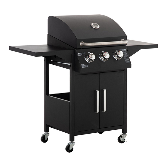
Outsunny 846-103V91 Montageanleitung

Verwandte Anleitungen für Outsunny 846-103V91


Inhaltszusammenfassung für Outsunny 846-103V91
- Seite 1 INb1a019_DE 846-103V91 IMPORTANT, RETAIN FOR FUTURE REFERENCE: READ CAREFULLY ASSEMBLY & INSTRUCTION MANUAL...
-
Seite 3: Sicherheitshinweise
SICHERHEITSHINWEISE 1.Lea cuidadosamente el manual de instrucciones antes de utilizar la parrilla y guárdelo para las referencias futuras. El incumplimiento de las instrucciones puede causar lesiones personales, daños a la propiedad incluso la muerte. 2.Solo es apta para ser utilizada en exteriores. No la utilice en interiores. 3.No la utilice por debajo del nivel del suelo. - Seite 4 STÜCKLISTE Pic. Pic. M4 x 8 Schraube +2(spare) M5*12 Schraube Stift der oberen Tür Unterer Türstif M3 x Mutter M3 x 10 Schraube M3 x 10 Blechschraube...
- Seite 5 Montage Hinweis: Ziehen Sie die Schrauben und Muttern erst an, wenn alle Montageschritte abgeschlossen sind. Schraube M3 x 10 x2 M3 x 10 Schraube x 2 Mutter M3 x 2 1.Befestigen Sie den linken und rechten Rahmen (5C) mit acht M5-Schrauben (B) an den linken und rechten Beinen (5A, 5B, 6A &...
- Seite 6 Montage 2.Befestigen Sie den linken und rechten Rahmen mit vier M5-Schrauben (B) an der unteren Ablage (7).
- Seite 7 Montage 3.Befestigen Sie die hintere Ablage (9) mit vier M5-Schrauben (B) an den Rahmen.
- Seite 8 Montage 4.Befestigen Sie den vorderen Träger (8) mit vier M5-Schrauben (B) an der Vorderseite der Rahmen.
- Seite 9 Montage 5.Befestigen Sie die vier Räder (10 & 11) an den Enden der Rahmenbeine. Hinweis: Die beiden Räder mit Bremsen (10) befinden sich immer auf der gleichen Seite.
- Seite 10 Montage 6.Der Körper (1) wird mit acht M5-Schrauben in die Rahmenbeine eingesetzt (siehe Abbildung). Ziehen Sie die Schrauben an, wenn der Körper in Position ist.
- Seite 11 Montage 7.Die linke Seitenablage (14) wird mit sechs M5-Schrauben (B) am Körper befestigt.
- Seite 12 Montage 8.Die rechte Seitenablage (15) wird mit sechs M5-Schrauben (B) am Körper befestigt.
- Seite 13 Montage 9.Befestigen Sie die Griffe (13) mit vier M4-Schrauben (A) an den vorderen Türen (12).
- Seite 14 Montage 10.Befestigen Sie die Tür mit den oberen und unteren Stiften (C & E) an den vorderen Beinen des Rahmens.
- Seite 15 Montage 11.Warmhalterost (2), Kochroste (3) und Wärmezelte (4) werden in den Körper eingesetzt.
- Seite 16 Montage 12.Befestigen Sie die Ölschale (21) an der Ölwanne. Ziehen Sie alle Schrauben vor dem Gebrauch fest. Montage abgeschlossen...
- Seite 17 Montage Ziehen Sie alle Schrauben vor dem Gebrauch fest. Montage abgeschlossen...
- Seite 18 INb1a019_DE 846-103V91 IMPORTANT, RETAIN FOR FUTURE REFERENCE: READ CAREFULLY ASSEMBLY & INSTRUCTION MANUAL...
-
Seite 20: Safety Instructions
SAFETY INSTRUCTIONS 1. Read the instruction manual carefully before use and keep it for future reference. Failure to comply with the instructions can result in death, serious injury or property damage. 2. For outdoor use ONLY! Do not use indoors. 3. -
Seite 21: Part List
PART LIST Pic. Pic. M4 *8 screw +2(spare) M5*12 screw Top door pin Bottom door pin M3*nut M3*10 screw M3*10 self-tap screw... - Seite 22 Assembly Note: Please do not tight the screws and nuts till all assembly steps completed. M3 * 10 screw x 2 M3*10 st x 2 M3 nut x 2 1. Assemble the LH and RH frame plates (5C) to LH & RH legs (5A, 5B, 6A &...
- Seite 23 Assembly 2. Assemble the LH and RH frame to bottom shelf (7) with 4pcs M5 screws (B).
- Seite 24 Assembly 3. Assemble the back shelf (9) to the frames with 4 pcs M5 screws (B).
- Seite 25 Assembly 4. Assemble the front beam (8) to the front of frames with 4pcs M5 screws (B).
- Seite 26 Assembly 5. Assemble the 4pcs wheels (10&11) to the end of frame legs. Note: the 2pcs wheels with break (10) are always in the same side.
- Seite 27 Assembly 6. The body (1) is slided into the frame legs with 8 pcs pre-assembled M5 screws (See detailed pic.). Tight screws after body slided into position. Thermometer (23) is fixed to the lid by its own screw. Note: make sure the 8pcs screws are pre-assembled before sliding.
- Seite 28 Assembly 7. LH side shelf (14) is asssembled to the body with 6 pcs M5 screws (B).
- Seite 29 Assembly 8. RH side shelf (15) is asssembled to the body with 6 pcs M5 screws (B).
- Seite 30 Assembly 9. Handles (13) are assembled to front doors (12) with 4pcs M4 screws (A). Totally 2 pcs doors.
- Seite 31 Assembly 10. Doors are assembled to frames’ front legs with top and bottom pins (C&E).
- Seite 32 Assembly 11. Warming grid (2), cooking grids (3) and heat tents (4) are fixed into the body.
- Seite 33 Assembly 12. Oil cup (21) is assembled to the oil pan.
- Seite 34 Assembly Tight all screws before use Assembly completed...