IK Multimedia iRig Pro Quattro I/O Schnellstartanleitung
Professionelles mobiles recording-interface/mixer
Verfügbare Sprachen
Verfügbare Sprachen
Quicklinks
QUICK START GUIDE
EN
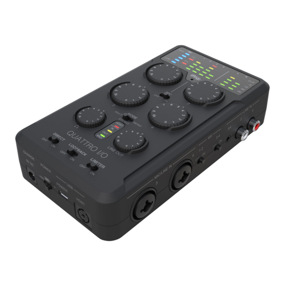
iRig Pro Quattro I/O
1
2
5
7
6
11
13
14
17
18
1.
External DC power input - 2-pole barrel socket. 9V DC,
1.75A (max), positive on the external pole. When iRig Pro
Quattro I/O is connected to a Lightning iOS device, using
this DC In with the optional PSU (included in Deluxe version)
will charge the connected iPhone or iPad.
2.
Power switch - 3-position switch turns the power on and
off.
3.
External micro-USB power input - powers up the unit by
using an external USB power supply capable of providing
5VDC and at least 1A (performance may vary depending
on micro-USB cable used: cable size 22AWG or greater is
recommended).
4.
Host port - mini-DIN connector - connect the iRig Pro
Quattro I/O to your host with the supplied cable.
5.
Battery level meter - this meter display the residual level of
the internal AA batteries. When batteries are not in use, only
the HIGH LED is on.
6.
48V phantom power LEDs - these LEDs illuminate when
phantom power is active for inputs 1-2 and 3-4.
7.
Input meters - each input has a dedicated 5-segment peak
meter, with 1-second hold on CLIP , that indicates the level
of the input signal. The red Clip LED will illuminate when
your input signal reaches -0.1 dBFS. Use the gain controls
to keep the signal below this level.
8.
Output meters - these meters display the signal level
received back from the host. These meters have the same
range as the input meters (-50 dBFS to -0.1 dBFS).
9.
Built-in microphone - iRig Pro Quattro I/O's built-in
omnidirectional microphone capsule is located at the top of
the front panel. When using the built-in microphone, orient
the capsule towards the sound source being recorded.
10. Built-in microphone's switch - to activate the built-in
microphone, slide this switch to the ON position: when
active, the built-in microphone will replace the input 1 and
its gain can be controlled with the same potentiometer.
For detailed information, please refer to the User Manual
ikmanual.com/irigproquattroio
ikmultimedia.com/support
3
4
8
9
10
12
15
16
19
11. Input gain control - adjust the input gain for the signals at
Inputs 1, 2, 3 and 4 respectively.
12. Mode switch - this 3-position switch allows you to decide
how to route the 4 inputs: multichannel, stereo (with safety
channels) or mono (with safety channels).
13. Host LED - this LED illuminates when the unit is recognised
by the host to which it is connected.
14. Headphone level - this knob controls the level for the 1/8"
TRS headphone output.
15. Line out level - this knob controls the level for the 2
balanced XLR outputs as well as the 1/8" TRS stereo
output.
16. MIDI IN/OUT LEDs - these LEDs illuminate when MIDI data
is received from/transmitted to the MIDI ports.
17. Direct monitor - iRig Pro Quattro I/O provides a direct
monitoring path from the inputs to the outputs. When direct
monitoring is enabled, the input signal is mixed with the
output signal from your audio software and routed directly
to both the line and headphone outputs.
18. Loopback - the audio that is input to the iRig Pro Quattro
I/O from your host is returned back to the host thru inputs
1 and 2. It is possible to control the level of the loopback
stream with the host volume's control.
19. Limiter - the limiter reduces the level when input signals
exceed a set level. Set the Limiter switch on, this will affect
inputs 1 and 2 only (either microphone and instrument).
20. RCA line inputs 3 and 4 - use these RCA inputs with
unbalanced line-level devices. These inputs are direct-to-
ADC. As such, no gain control available.
21. 1/8" TRS line inputs 3 and 4 - use this stereo 1/8" TRS
jack input with unbalanced line-level devices. This input is
direct-to-ADC. As such, no gain control available. Please
note that this input will not provide plug-in power for
external 1/8" TRS microphones.
ikmultimedia.com/warranty
Professional mobile recording interface/mixer
20
21
22
23
Made in Italy
24
29
25
26
27
28
30
22. 48V phantom power switches - these switches enable
48V phantom power on microphone inputs 1-2 and 3-4
respectively. Front panel LEDs illuminate when phantom
power is selected.
23. Microphone/Line inputs 3 and 4 - XLR Combo type input
sockets - connect microphones or balanced line level
signals. The gain control on the top panel provides gain for
both input types.
24. Microphone/Instrument inputs 1 and 2 - XLR Combo type
input sockets - connect microphones or Hi-Z instruments
signals. The gain control on the top panel provides gain for
both input types.
25. MIDI IN/OUT - 2.5 mm jacks for connection of external
MIDI equipment.
26. Headphone output - connect one pair of headphone to
this 1⁄8" (3.5 mm) TRS jack socket.
27. Stereo line output - this 1⁄8" (3.5 mm) TRS jack allows you
to send the audio signal to a video camera or other device
while monitoring with headphones.
28. Balanced line outputs - outputs 1/L and 2/R are balanced
analog line outputs on 3-pin male XLR sockets; outputs
1/L and 2/R will normally be used to drive the primary
monitoring system.
29. Battery compartment - battery compartment for 4xAA
batteries.
30. Standard UNC 1/4"-20 thread adapter - use this thread
adapter to attach the iRig Pro Quattro I/O to any 1/4" UNC
support.
31. 2 x iRig MIC XY stereo microphones* - pair of quality
condenser microphones with cardioid polar pattern,
extended frequency response and wide dynamic range that
can be used in multiple situations, from the studio to field
recording.
*iRig MIC XY stereo microphones are included in iRig
Pro Quattro I/O Deluxe package only (8 025813 896031)
*
31

Verwandte Anleitungen für IK Multimedia iRig Pro Quattro I/O

Inhaltszusammenfassung für IK Multimedia iRig Pro Quattro I/O
-
Seite 5: Quick Start
(3,5 mm) lassen sich Audiosignale an eine Videokamera verfügt über eine Peakanzeige für den entsprechenden 18. Loopback - Die vom Host in das iRig Pro Quattro I/O oder ein anderes Gerät senden, während Sie mit einem Eingangspegel mit einer Haltezeit von 1s bei Übersteuerung.