
Inhaltszusammenfassung für Pinter MANOCOMB - IP65
- Seite 1 Bedienungsanleitung Operating Instructions MANOCOMB - IP65 ® MANOCOMB - IP65/CV ® MANOCOMB - IP65/PN ®...
- Seite 2 MANOCOMB®-IP65 Bedienungs- und Wartungsanleitung...
-
Seite 3: Inhaltsverzeichnis
Kapitel 5: Technische Daten MANOCOMB-IP65 ............8 Kapitel 6: Technische Daten MANOCOMB-IP65/CV ..........14 © Alle Rechte bei PINTER Mess- und Regeltechnik GmbH, auch für den Fall von Kapitel 7: Technische Daten MANOCOMB-IP65/PN ..........20 Schutzrechtsanmeldungen. Jede Verfügungsbefugnis, wie Kopie- und Weiter- Kapitel 8: Schaltpunkteinstellung ................... -
Seite 4: Kapitel 1: Zu Dieser Anleitung
MANOCOMB®-IP65 Bedienungs- und Wartungsanleitung Zu dieser Anleitung Beachten Sie außerdem allgemein gültige, gesetzliche und sonstige ver- bindliche Regelungen der europäischen bzw. nationalen Gesetzgebung Diese Anleitung enthält wichtige Informationen, um den MANOCOMB-IP65 sowie die in Ihrem Land gültigen Vorschriften zur Unfallverhütung und Druckschalter sicher und sachgerecht zu montieren, zu bedienen, zu warten und einfache Störungen selbst zu beseitigen. - Seite 5 MANOCOMB®-IP65 Bedienungs- und Wartungsanleitung Qualifikation des Personals technischen Daten angegeben ist. • Belasten Sie das Gerät unter keinen Umständen mechanisch. Verwen- Die Montage und Inbetriebnahme erfordert grundlegende elektrische Kennt- den Sie das Gerät niemals als Griff oder Stufe. Stellen Sie keine Gegen- nisse sowie Kenntnisse der verwendeten Fachbegriffe.
-
Seite 6: Kapitel 3: Lieferumfang
MANOCOMB®-IP65 Bedienungs- und Wartungsanleitung die elektrischen Kontakte beschädigen können. Einsatzbereiche Der MANOCOMB-IP65 ist ein Druckschalter für den industriellen Einsatz und Während des Betriebs entspricht dem Stand der Technik. Wenn das Gerät nicht ordnungsgemäß befestigt ist, können andere Anlagen- teile durch unkontrollierte Bewegungen des Geräts beschädigt, wie auch Per- Der MANOCOMB-IP65 ist zugelassen für die Verwendung: sonen verletzt werden. - Seite 7 MANOCOMB®-IP65 Bedienungs- und Wartungsanleitung Druckbegrenzer mit Verriegelung der Schaltzustände Bei Begrenzerfunktionen ist es zwingend erforderlich den Abschaltzustand zu erhalten und zu verriegeln. Erst nach Beseitigung der Ursache, die zur Abschal- tung führte, darf die Verriegelung gelöst und die Anlage wieder in Betrieb genommen werden.
- Seite 8 MANOCOMB®-IP65 Bedienungs- und Wartungsanleitung Typenschlüssel MANOCOMB-IP65 (gängiste Ausführungen und Optionen) Übersicht mit gängisten Optionen Aufbau Materialnummer M 0 a b c d - e (f) - g h i a / Zertifizierung Standardausführung (CE-Kennzeichnung) a / Zertifizierung SIL, TÜV, DGR Zulassung b / Schaltfunktion 1K (1x Wechslerkontakt) b / Schaltfunktion...
- Seite 9 MANOCOMB®-IP65 Bedienungs- und Wartungsanleitung Übersicht mit gängisten Optionen Aufbau Materialnummer M 0 a b c d - e (f) - g h i e+f / Druckbereiche siehe Typenschild g / Prozessanschluss G 1/4 B, Messing g / Prozessanschluss G 1/4 B, Edelstahl 1.4571/1.4404 (AISI 316Ti/316L) g / Prozessanschluss G 1/2 B, Messing g / Prozessanschluss...
-
Seite 10: Kapitel 5: Technische Daten Manocomb-Ip65
MANOCOMB®-IP65 Bedienungs- und Wartungsanleitung Technische Daten MANOCOMB-IP65 Funktion mechanischer Druckschalter; Kraft-Waage-Messsystem mit Balgsensor Lebensdauer mindestens 10 Mio Lastwechsel Niederdruckbereiche 0 - 60 mbar bis 0 - 600 mbar Normaldruckbereiche 0 - 1 bar bis 0 - 60 bar Hochdruckbereiche 0 - 100 bar bis 0 - 400 bar Differenzdruck maximales Verhältnis zwischen statischem Druck und Differenzdruck 10:1 Vakuumbereiche... - Seite 11 MANOCOMB®-IP65 Bedienungs- und Wartungsanleitung Schaltgenauigkeit abhängig von Schaltkontakt - siehe Folgeseite Wiederholgenauigkeit < 0,5% FS Schaltdifferenz (Hysterese) abhängig von Schaltkontakt - siehe Folgeseite Prozessanschluss G 1/4 B (EN837) Elektrischer Anschluss Reihenklemmen & M20 Kabelverschraubung Gewicht ca. 1,5 kg (je nach Schaltfunktion und Materialauswahl) Schutzart IP65 Optionale Ausführungen...
- Seite 12 MANOCOMB®-IP65 Bedienungs- und Wartungsanleitung Elektrischer Anschluss Elektrische Daten Belegung für alle Schalt- zusätzliche Belegung für Schaltvermögen max. zulässiger Dauerstrom I max [A] bei ohmscher Belastung Mikroschalter funktionen 2K-Ausführungen Bezugschaltzahl: 30/min; Bezugstemperatur: +30°C Schlie- Schlie- El. Anschluss Öffner Öffner Mikroschalter U [V] 24 V 48 V 60 V...
- Seite 13 MANOCOMB®-IP65 Bedienungs- und Wartungsanleitung Einbaumaße MANOCOMB-IP65 MANOCOMB-IP65 Standardausführung (1K,1KA, 2K, 2KA) Standardausführung (2KP, 2K2AP, 1KPDi, 1K2APDi)
- Seite 14 MANOCOMB®-IP65 Bedienungs- und Wartungsanleitung Typenschlüssel MANOCOMB-IP65/CV (gängiste Ausführungen und Optionen) Übersicht mit gängisten Optionen Aufbau Materialnummer M 0 V b c d - e - g h i b / Schaltfunktion 1K (1x Öffner, 1x Schließer) b / Schaltfunktion 1KA (1x Öffner, 1x Schließer, 1x integriertes Manometer) c / Material Messing, FKM c / Material...
- Seite 15 MANOCOMB®-IP65 Bedienungs- und Wartungsanleitung Übersicht mit gängisten Optionen Aufbau Materialnummer M 0 V b c d - e - g h i i / weitere Optionen ohne weitere Optionen i / weitere Optionen öl- und fettfreie Ausführung i / weitere Optionen Haube plombierbar i / weitere Optionen Schaltpunkt(e) werkseitig eingestellt und plombiert...
-
Seite 16: Kapitel 6: Technische Daten Manocomb-Ip65/Cv
MANOCOMB®-IP65 Bedienungs- und Wartungsanleitung Technische Daten MANOCOMB-IP65/CV Funktion mechanischer Druckschalter; Kraft-Waage-Messsystem mit Balgsensor Lebensdauer mindestens 10 Mio Lastwechsel Normaldruckbereiche 0 - 1 bar bis 0 - 60 bar Hochdruckbereiche 0 - 100 bar bis 0 - 400 bar Überdrucksicherheit > 1,5x FS Vakuumsicherheit -1 bar Werkstoff Gehäuse... - Seite 17 MANOCOMB®-IP65 Bedienungs- und Wartungsanleitung Prozessanschluss G 1/4 B (EN837) Elektrischer Anschluss Reihenklemmen & M20 Kabelverschraubung Gewicht ca. 1,5 kg (je nach Schaltfunktion und Materialauswahl) Schutzart IP65 Optionale Ausführungen Sondermessbereiche; erhöhte Überdrucksicherheit Sondermaterialien; dichtungsfreie Ausführung; öl- und fettfreie Ausführung; buntmetallfreie Ausführung Prozessanschluss: alle gängigen Gewindeanschlüsse;...
- Seite 18 MANOCOMB®-IP65 Bedienungs- und Wartungsanleitung Elektrischer Anschluss Elektrische Daten Schaltvermögen max. zulässiger Dauerstrom I max [A] bei ohmscher Belastung Belegung für alle Schaltfunktionen Bezugschaltzahl: 30/min; Bezugstemperatur: +30°C El. Anschluss Öffner Schließer U [V] 24 V 48 V 60 V 110 V 240 V SD [%] I [A] AC...
- Seite 19 MANOCOMB®-IP65 Bedienungs- und Wartungsanleitung Einbaumaße MANOCOMB-IP65 /CV Standardausführung (1K,1KA)
- Seite 20 MANOCOMB®-IP65 Bedienungs- und Wartungsanleitung Typenschlüssel MANOCOMB-IP65/PN (gängiste Ausführungen und Optionen) Übersicht mit gängisten Optionen Aufbau Materialnummer M 0 P b c d - e (f) - g h i b / Schaltfunktion 1K (1x Pneumatikventil) b / Schaltfunktion 1KA (1x Pneumatikventil, 1x integriertes Manometer) b / Schaltfunktion 2K (2x Pneumatikventil) b / Schaltfunktion...
- Seite 21 MANOCOMB®-IP65 Bedienungs- und Wartungsanleitung Übersicht mit gängisten Optionen Aufbau Materialnummer M 0 P b c d - e (f) - g h i e+f / Druckbereiche siehe Typenschild g / Prozessanschluss G 1/4 B, Messing g / Prozessanschluss G 1/4 B, Edelstahl 1.4571/1.4404 (AISI 316Ti/316L) g / Prozessanschluss G 1/2 B, Messing g / Prozessanschluss...
-
Seite 22: Kapitel 7: Technische Daten Manocomb-Ip65/Pn
MANOCOMB®-IP65 Bedienungs- und Wartungsanleitung Technische Daten MANOCOMB-IP65/PN Funktion mechanischer Druckschalter; Kraft-Waage-Messsystem mit Balgsensor Lebensdauer mindestens 10 Mio Lastwechsel Normaldruckbereiche 0 - 1 bar bis 0 - 60 bar Hochdruckbereiche 0 - 100 bar bis 0 - 400 bar Differenzdruck maximales Verhältnis zwischen statischem Druck und Differenzdruck 10:1 Vakuumbereiche -1...0 bar bis -60...0 mbar Überdrucksicherheit... - Seite 23 MANOCOMB®-IP65 Bedienungs- und Wartungsanleitung Wiederholgenauigkeit < 0,5% FS Schaltdifferenz (Hysterese) ca. 3% - 4% FS (abhängig von Versorgungsluftdruck) Prozessanschluss G 1/4 B (EN837) pneumatischer Anschluss G 1/4 B (EN837) Versorgungsluftdruck 2 - 8 bar (4 bar empfohlen) Versorgungsmedium 5 µm, geölte oder gefilterte nicht geölte Druckluft oder andere nicht explosionsfähige gasförmige Medien nach ISO-VG 10 Gewicht ca.
- Seite 24 MANOCOMB®-IP65 Bedienungs- und Wartungsanleitung Pneumatischer Anschluss Daten für den pneumatischen Anschluss Der MANOCOMB-Druckschalter ist wahlweise mit 1 oder 2 pneumatischen Die Schaltfunktion ist gewährleistet, wenn der Versorgungsluftdruck mindes- Grenztastern ausgestattet (3/2-Wege-Ventile). tens 2 bar und maximal 8 bar beträgt. Standardmäßig wird der MANOCOMB- Schliessen Sie die Versorgungsluft an den Lufteingang 1 (bei 1K und 2K-Ver- Druckschalter bei 4 bar Versorgungsluft justiert.
- Seite 25 MANOCOMB®-IP65 Bedienungs- und Wartungsanleitung Einbaumaße MANOCOMB-IP65 /PN Standardausführung (1K,1KA, 2K, 2KA)
-
Seite 26: Kapitel 8: Schaltpunkteinstellung
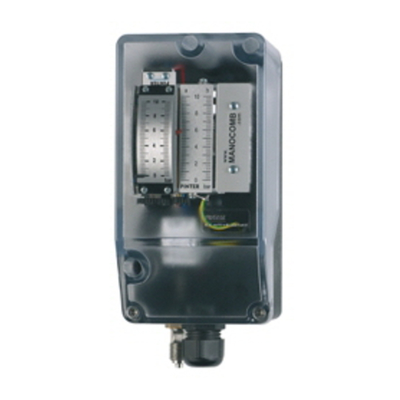
MANOCOMB®-IP65 Bedienungs- und Wartungsanleitung Schaltpunkteinstellung Istwertanzeige (1) Sollwertskala (2) Schaltpunkteinstellung B (3b) Zur Kontakteinstellung bitte Klarsichthaube abnehmen. Bei plombierbarer Haube, den Plombierstutzen nicht verlieren. Die Einstellung des Schaltpunkts A erfolgt durch Drehen des Zahnrades (3A). Die Einstellung des Schaltpunkts B (nur 2K-Modelle) erfolgt durch Drehen des Zahnrades (3B). - Seite 27 MANOCOMB®-IP65 Bedienungs- und Wartungsanleitung...
- Seite 28 MANOCOMB®-IP65 Operating Instructions...
- Seite 29 Chapter 4: Usage ......................... 32 Chapter 5: Technical data MANOCOMB-IP65 ............34 © All rights reserved for PINTER Mess- und Regeltechnik GmbH, also in case of Chapter 6: Technical data MANOCOMB-IP65/CV ........... 40 patent applications. Chapter 7: Technical data MANOCOMB-IP65/PN ........... 46 Chapter 8: Set point adjustment ..................
- Seite 30 MANOCOMB®-IP65 Operating Instructions About these instructions of the European or national legislation as well as the regulations in your country for accident prevention and environmental protection. These instructions contains important information, in order to safely and pro- perly install, operate and maintain the MANOCOMB-IP65 Pressure Switch and also information on how to fix simple failures youself.
- Seite 31 MANOCOMB®-IP65 Operating Instructions Installation and setup therefore must only be made by a skilled technician or Before the installation an instructed person under the direction of a supervising skilled technician. Let the device acclimatize for several hours prior to the installation, because An instructed person is considered a person who, based on his professional otherwise condensation water might precipitate at the housing.
- Seite 32 MANOCOMB®-IP65 Operating Instructions Cleaning the device Application Never use solvents or harsh detergents. The MANOCOMB-IP65 is a Pressure Switch for industrial applications and re- Clean only with a slightly moist cloth, use only water and if necessary a mild flects the state of the art. detergent.
- Seite 33 MANOCOMB®-IP65 Operating Instructions Utilization as Safety Pressure Limiter With limiter functions, it is absolutely necessary to maintain the switch-off state and to lock it. Only after eliminating the cause that led to the shutdown, the lock may be released and the system again put into operation. Safety Pressure Limiter with external interlock The MANOCOMB-IP65 can be used as a pressure limiter for MAX pressure and/or MIN pressure, when the switch-off state is locked for example via a next...
- Seite 34 MANOCOMB®-IP65 Operating Instructions Part number codes MANOCOMB-IP65 (most common options) codes for most common options part number structure M 0 a b c d - e (f) - g h i a / approvals standard version (CE marking) a / approvals SIL, TÜV, PED approval b / switching function 1K (1x SPDT)
- Seite 35 MANOCOMB®-IP65 Operating Instructions part number codes part number structure M 0 a b c d - e (f) - g h i e+f / pressure ranges see type plate g / process connection (wetted) 1/4“ BSP male, brass g / process connection (wetted) 1/4“...
- Seite 36 MANOCOMB®-IP65 Operating Instructions Technical data MANOCOMB-IP65 function mechanical pressure switch; force balance measuring system with bellows sensors life cylce at least 10 mio switch cycles low pressure ranges 0 - 60 mbar to 0 - 600 mbar normal pressure ranges 0 - 1 bar to 0 - 60 bar high pressure ranges 0 - 100 bar to 0 - 400 bar (requires wetted parts in stainless steel)
- Seite 37 MANOCOMB®-IP65 Operating Instructions switching accuracy please see electrical data repeatabilty < 0,5% FS switching differential (hysteresis) please see electrical data process connection 1/4“ BSP male (EN837) electrical connection terminal blocks & M20 cable gland weight approx. 1,5 kg (depending on switching function and material) protection IP65 Options...
- Seite 38 MANOCOMB®-IP65 Operating Instructions Electrical connection Electrical data assignment for all additional assignment for max. permissable steady current I max [A] - ohmic load micro switch switching functions 2K-versions reference switch cycle: 30/min; reference temperature: +30°C El. connection micro switch U [V] 24 V 48 V 60 V...
- Seite 39 MANOCOMB®-IP65 Operating Instructions Dimensions MANOCOMB-IP65 MANOCOMB-IP65 Standard version (1K,1KA, 2K, 2KA) Standard version (2KP, 2K2AP, 1KPDi, 1K2APDi)
- Seite 40 MANOCOMB®-IP65 Operating Instructions Part number codes MANOCOMB-IP65/CV (most common options) codes for most common options part number structure M 0 V b c d - e - g h i b / switching function 1K (1x NC, 1x NO) b / switching function 1KA (1x NC, 1x NO, 1x integrated pressure gauge) c / material wetted parts brass, FKM...
- Seite 41 MANOCOMB®-IP65 Operating Instructions codes for most common options part number structure M 0 V b c d - e - g h i i / further options no further options i / further options cleaned for O2 service i / further options cover lead-sealable i / further options enclosure equipped with Gore®...
- Seite 42 MANOCOMB®-IP65 Operating Instructions Technical data MANOCOMB-IP65/CV function mechanical pressure switch; force balance measuring system with bellows sensors life cylce at least 10 mio switch cycles normal pressure ranges 0 - 1 bar to 0 - 60 bar high pressure ranges 0 - 100 bar to 0 - 400 bar (requires wetted parts in stainless steel) over pressure safety >...
- Seite 43 MANOCOMB®-IP65 Operating Instructions process connection 1/4“ BSP male (EN837) electrical connection terminal blocks & M20 cable gland weight approx. 1,0 kg protection IP65 Options special scales and units; extended overpressure safety special materials; cleaned for O2 service; nonferrous metal free version process connection: all common threads;...
- Seite 44 MANOCOMB®-IP65 Operating Instructions Electrical connection Electrical data max. permissable steady current I max [A] - ohmic load reference switch cycle: 30/min; reference temperature: +30°C El. Anschluss U [V] 24 V 48 V 60 V 110 V 240 V SD [%] I [A] AC terminal blocks I [A] DC...
- Seite 45 MANOCOMB®-IP65 Operating Instructions Dimensions MANOCOMB-IP65 /CV Standard version (1K,1KA)
- Seite 46 MANOCOMB®-IP65 Operating Instructions Part number codes MANOCOMB-IP65/PN (most common options) codes for most common options part number structure M 0 P b c d - e (f) - g h i b / switching function 1K (1x pneumatic valve) b / switching function 1KA (1x pneumatic valve, 1x integrated pressure gauge) b / switching function 2K (2x pneumatic valve)
- Seite 47 MANOCOMB®-IP65 Operating Instructions codes for most common options part number structure M 0 P b c d - e (f) - g h i e + f / pressure range see type plate g / process connection (wetted) 1/4“ BSP male, brass g / process connection (wetted) 1/4“...
- Seite 48 MANOCOMB®-IP65 Operating Instructions Technische Daten MANOCOMB-IP65/PN function mechanical pressure switch; force balance measuring system with bellows sensors life cylce at least 10 mio switch cycles normal pressure ranges 0 - 1 bar to 0 - 60 bar high pressure ranges 0 - 100 bar to 0 - 400 bar (requires wetted parts in stainless steel) differential pressure max.
- Seite 49 MANOCOMB®-IP65 Operating Instructions repeatabilty < 0,5% FS switching differential (hysteresis) ca. 3% - 4% FS (depending on supply air pressure) process connection 1/4“ BSP male (EN837) pneumatic connection 1/4“ BSP male (EN837) supply air pressure 2 - 8 bar (4 bar recommended) supply media 5 µm, lubricated or filtered non-lubricated compressed air or any other according to ISO-VG 10 weight...
- Seite 50 MANOCOMB®-IP65 Operating Instructions pneumatic connection pneumatic data The MANOCOMB pressure switch is equipped with 1 or 2 pneumatic limit swit- The switching function is guaranteed if the supply air pressure is at least 2 bar ches (3/2-way valves). and a maximum of 8 bar. The MANOCOMB pressure switch is calibrated at 4 Connect the supply air to the inlet 1 (for 1K and 2K versions) as well as the bar supply air by factory default.
- Seite 51 MANOCOMB®-IP65 Operating Instructions Dimenstions MANOCOMB-IP65 /PN Standard version (1K,1KA, 2K, 2KA)
- Seite 52 MANOCOMB®-IP65 Operating Instructions Set point adjustment actual value indicator (1) set point scale (2) set point adjustment B (3b) To adjust the contact(s), please remove the transparent cover of the enclosure. Be careful not to loose the lead-seal when transparent covers is equipped with this option.
- Seite 53 MANOCOMB®-IP65 Operating Instructions...
- Seite 54 MANOCOMB®-IP65 Operating Instructions...
- Seite 55 MANOCOMB®-IP65 Operating Instructions...
- Seite 56 PINTER Mess- und Regeltechnik GmbH Kraichgaublick 17 Technologiepark Neckartal-Odenwald 74847 Obrigheim, Deutschland Phone +49-6262-92670-0 +49-6262-92670-99 E-Mail info@pinter-gmbh.de Internet www.pinter-gmbh.com...