Werbung
Verfügbare Sprachen
Verfügbare Sprachen
Quicklinks
This product is covered by one or more of the following patents.
DE202014007924.2U9; IT280386; EP1148346B1
(see www.patents.datalogic.com for patent list)
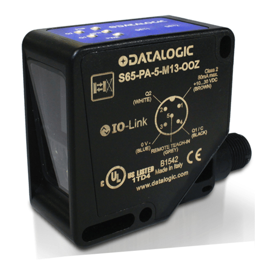
S65-PA-5-M13
Time-of-flight infrared background suppression sensor
INSTRUCTION MANUAL
SIGNALS
OUTPUT LED (yellow)
Yellow LEDs on, numbered as 1 and 2,
indicate activation of Q1 and Q2 outputs.
LEDs blink at the same time if measurement
is out of range or not available due to the
presence of environmental contamination.
POWER LED (green)
Green PWR LED on indicates that the device is switched on and
operating.
ACTIVE SETUP LED (green)
Green PNP/NPN LEDs on indicate that the device is in the selected
setup.
OUTPUT and POWER LEDS also indicate setup settings (see "Setup"
chapter).
INSTALLATION
Sensor can be installed by means of the two through holes present on
the body, using screws (M4x35 or longer; max. tightening torque: 1Nm)
with washers and nuts.
If mating surface is not perfectly flat, a bracket is recommended.
Various adjustable brackets are available to help sensor positioning (see
accessories on the catalogue). Operating distance is measured from the
front surface of the sensor optics.
M12 connector can be aimed in two different ways, by working the
relevant retaining spring and turning the unit by 90° until it stops.
1) Connect and fasten M12 connector when power is off.
2) Connect power cable and/or I/O as indicated for every model.
3) Fasten sensor to suitable support, making sure to first align the green
pointer at the centre of the target
4) Sensor function will be available in a few seconds from switch-on.
.
5) Allow warm-up time before starting normal operations
CONNECTIONS
S65-PA-5-M13-OO
S65-PA-5-M13-OOZ
NOTE: Wire colour refers to European standard.
S65-PA-5-M13-OO ADJUSTMENT
1. Set up the device as needed. Press SET1+SET2 > 3 sec until the 3 green
LEDs blink to enter the setup menu.
- Press SET 2 to navigate within the menu until output → →
- Press SET 1 to select setup.
- Press SET1 and SET2 > 6 sec to go back to
default setup. The new configuration will be saved
only when exit to the menu. The sensor system
will
automatically
reset
to
the
original
configuration if a new configuration is not detected
within 10 seconds.
2. Select hysteresis according to the application,
considering the environmental and the more critical
operating conditions.
3. Identify the target reading point using the green
visible pointer by pressing SET1 (or SET2) for 1 sec
< t < 3 sec (the pointer will remain active for 5 sec).
4. Make sure that the spot is inside the target surface to be acquired.
5. Target Acquisition: Press SET1 (or SET2) > 3sec to teach-in switching
point 1 or 2 until the yellow LED Q1 (or Q2) flashes.
NOTE: a spot partialization could change detection performances.
PNP/NPN
MODE menu
Press SET1+SET2 for t > 3 sec, until all 3
Q1 ON =
green LEDs are flashing. Releasing the
Setup
buttons, the sensor enters MODE menu.
PNP
Press SET2 to navigate within the menu
for both outputs
(→→), press SET1 to select setup.
available during I/O Link communication)
Restore Default Setup
Green Pointer
t > 6 sec
Press SET1 + SET2 for at least 6 sec; before
Press SET1 (or SET2) for 1 sec. < t < 3 sec
default setup there is a temporary darkening of
to switch on the green pointer
all LEDs, after which it is possible to release
the buttons.
Supply voltage:
Consumption:
Operating Distance:
Minimum teach distance:
Hysteresis:
Response time:
Difference White 90%/Grey 18% and White 90%/Black 6%:
Thermal compensation error:
Switching output:
Teach-in Input:
Warming-up time:
Warnings:
Operating temperature:
Storage temperature:
Electrical strength:
Insulation resistance:
Reading spot size:
Pointer spot size (green):
Max. deviation of pointer/reading spot axes origin:
Emission and Wavelength:
Ambient light rejection:
Vibrations:
Shock resistance:
Humidity:
Exposed material:
Front side material:
Mechanical protection:
Connections:
(Overall) Dimensions:
Weight:
I/O LINK Connection:
UL (requirements):
Factory settings and default settings are (for both Q1 and Q2): PNP OUT, LIGHT mode, Switching distance 2 m, hysteresis = 80mm
READING AREA DIMENSIONS
Typical spot size – squared section
SETUP
LIGHT/DARK
Q2 ON =
Q1 ON =
Q2 ON =
Q1 ON =
Setup
setup
setup
80 mm
NPN
LIGHT
DARK
hysteresis
for both outputs
(NPN is not
Teach-In
1 sec < t < 3 sec
t > 3 sec
Point the target. Press SET1 (or SET2) > 3 sec
until Q1 (or Q2) blinks, then release button to
acquire the target
TECHNICAL DATA
S65-PA-5-M13-OO
S65-PA-5-M13-OOZ
24 VDC ± 20%
< 2.2 W (excluding any loads)
0.3..5 m (90% white) /
0.3..4.5 m (18% grey) /
0.3..3.5 m (6 % black)
400 mm
30mm / 50mm / 80mm
8.5 msec max.
see chart (value Typ, 1σ, T=25°C, ambient light <1Klux)
1.5 mm /°C (T ≠ 25°C)
Can be set up (PNP NPN / Light Dark) 100mA max.
Active High (+24V) 1 sec < t < 3 sec → teach Q1 / 3 sec < t < 6 sec → teach Q2
20 min typ
Q1 (YELLOW) / Q2 (YELLOW) / ON PWR (GREEN) - PNP / NPN (GREEN)
-15°... +55 °C (with device ON)
-25 ... +70 °C
500 VAC, 1 min between electronics and case
> 20 M, 500 VDC between electronics and case
typ 100x100 mm @ 5m
typ 200x200 mm @ 5m
+/- 40 mm
LED / 850 nm
according to EN 60947-5-2,
width 0.5 mm, frequency 10 ... 55Hz, per axis (EN60068-2-6)
11 ms (30 G) 6 shocks for each axis (EN60068-2-27)
< 90% no condensation
Body: ABS / Display: POLYESTER
PMMA
IP67
M12 - 5 poles
50 x 50 x 25 mm
50 g.max.
NO
(See parameter table on www.datalogic.com)
Class 2 power supply according to UL 508
OVERALL DIMENSIONS
HYSTERESIS
All the regulations and rules concerning electric and mechanical
safety must be complied with during sensor operation.
The sensor must be protected against mechanical damage.
Q2 ON =
Q1+Q2 ON =
50 mm
30 mm
This product is only for indoor use.
hysteresis
hysteresis
for both outputs
Key
This device requires no special maintenance operations.
At any rate, take care to clean the optics surface with a compatible
Status LED negligible
detergent in order to avoid degraded performance.
LED OFF
Use protections for the plastic parts in case of dangerous
Steady LED
environment.
LED ON and flashing
DIFFERENCE WHITE/GREY – WHITE/BLACK
The sensors are NOT safety devices, and so MUST NOT be used in
the safety control of the machines where installed.
Datalogic S.r.l.
Via S. Vitalino 13 - 40012 Calderara di Reno - Italy
Tel: +39 051 3147011 - Fax: +39 051 3147205 - www.datalogic.com
Helpful links at www.datalogic.com: Contact Us, Terms and Conditions, Support.
For information about the disposal of Waste Electrical and Electronic Equipment (WEEE), please
refer to the website at www.datalogic.com.
© 2021 Datalogic S.p.A. and/or its affiliates ALL RIGHTS RESERVED. Without limiting the rights
under copyright, no part of this documentation may be reproduced, stored in or introduced into a retrieval
system, or transmitted in any form or by any means, or for any purpose, without the express written
permission of Datalogic S.p.A. and/or its affiliates. Datalogic and the Datalogic logo are registered
trademarks of Datalogic S.p.A. in many countries, including the U.S.A. and the E.U. All other trademarks
and brands are property of their respective owners. Datalogic reserves the right to make modifications
and improvements without prior notification.
SAFETY WARNINGS
MAINTENANCE
821007522 Rev. C
Werbung

Verwandte Anleitungen für Datalogic S65-PA-5-M13


Inhaltszusammenfassung für Datalogic S65-PA-5-M13
- Seite 1 S65-PA-5-M13-OOZ Exposed material: Body: ABS / Display: POLYESTER © 2021 Datalogic S.p.A. and/or its affiliates ALL RIGHTS RESERVED. Without limiting the rights Front side material: PMMA under copyright, no part of this documentation may be reproduced, stored in or introduced into a retrieval...
- Seite 2 Gehäuse: ABS / Display: POLYESTER S65-PA-5-M13-OOZ PMMA Frontflächenmaterial: © 2021 Datalogic S.p.A. und/oder die Tochtergesellschaften ALLE RECHTE VORBEHALTEN. Ohne die im IP67 Schutzart: Urheberrecht festgelegten Rechte einzuschränken, darf kein Teil dieses Dokuments ohne die ausdrückliche schriftliche Erlaubnis von Datalogic S.p.A. und/oder den Tochtergesellschaften vervielfältigt, in einem Anschlüsse:...
- Seite 3 à quelque fin que ce soit, sans l'autorisation écrite expresse Dimensions (encombrement maximum) : 50 x 50 x 25 mm de Datalogic S.p.A. et/ou ses filiales. Datalogic et le logo Datalogic sont des marques de commerce de Datalogic Poids : 50 g max.
-
Seite 4: Manuale Istruzioni
Corpo : ABS / Display: POLYESTER S65-PA-5-M13-OOZ Materiale del frontale: PMMA © 2021 Datalogic S.p.A. e/o le sue consociate TUTTI I DIRITTI RISERVATI. Senza con ciò limitare i Protezione meccanica: IP67 diritti coperti dal copyright, nessuna parte della presente documentazione può essere riprodotta,... - Seite 5 +24 V ±20% Via S. Vitalino 13 - 40012 Calderara di Reno - Italy 读取光斑大小: (白色): Q2 最大电流 100mA 100x100 mm @ 5m(典型值) 电话:+39 051 3147011 - 传真:+39 051 3147205 - www.datalogic.com (蓝色): www.datalogic.com 上的网站帮助链接:联系我们、条款和条件、支持。 指针光斑大小(绿色): 200x200 mm @ 5m(典型值) (黑色):...