Hifonics hfc1200 Bedienungsanleitung
1.2 farad power capacitor
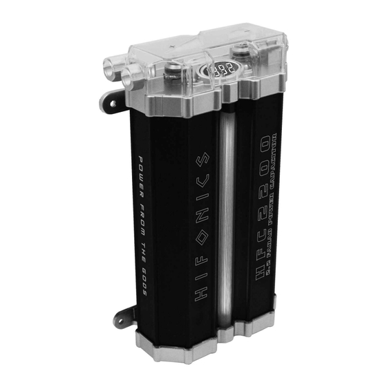
2.2 farad power capacitor

Inhaltszusammenfassung für Hifonics hfc1200
- Seite 1 H F C 1 2 0 0 1.2 FA R A D P O W E R C A PA C ITOR H F C 2 2 0 0 2 .2 FA R A D P OW E R C A PA C ITOR BEDIENUNGSANLEITUNG OWNER’S MANUAL...
-
Seite 2: Inhaltsverzeichnis
Seite Verwendungsmöglichkeiten Sicherheitshinweise Montage Erstes Aufladen Anschlussbeispiele Funktionsbeschreibung Entladen Justierung der Voltanzeige TECHNISCHE DATEN HFC1200 Kapazität: 1.2 Farad +/- 10% Dauer-Betriebsspannung: 11 ~ 16V DC Betriebstemperatur: – 40 ~ 80° C E.S.R.: 0,0015 Ohm @ 120hz / 25° Abmessungen: 148 x 65 x 185 mm HFC2200 Kapazität:... -
Seite 3: Verwendungsmöglichkeiten
VERWENDUNGSMÖGLICHKEITEN Der Pufferkondensator wird in Kraftfahrzeugen zur Stabilisierung und Unterstützung der Stromversorgung eines Verstärkers eingesetzt, wenn dieser schnell und für kurze Zeit hohe Ströme benötigt. Er kann kurzfristige Belastungen der Bordspannungen bei z.B. besonders tiefen, kräftigen Bässen ausgleichen. Durch die Verwendung des Pufferkondensators ergibt sich eine wesentlich bessere Leistungsentfaltung des Verstärkers. -
Seite 4: Sicherheitshinweise
SICHERHEITSHINWEISE Bevor Sie mit der Installation des Kondensators beginnen, sollten Sie die folgenden Anweisungen der Bedienungsanleitung genau befolgen! Andernfalls besteht Verletzungsgefahr oder das Gerät könnte ernsthaft beschädigt werden. Der Pufferkondensator entspricht der KFZ-Richtlinie für den Betrieb in Fahrzeugen innerhalb der Europäischen Union und besitzt eine E-Zertifizierung als auch eine CE-Kennzeichnung (Konformitätserklärung). -
Seite 5: Montage
MONTAGE Für bestmögliche Ergebnisse sollte der Kondensator so nahe wie möglich bei der Endstufe installiert werden. Die Kabel zwischen dem Kondensator und der Endstufe sollten möglichst kurz sein und einen möglichst großen Querschnitt aufweisen. Die Kabel sind so zu verlegen, dass deren Isolierung während des Einbaus und des Betriebes nicht beschädigt werden. -
Seite 6: Anschlussbeispiele
ANSCHLUSSBEISPIELE Anschluss mit Verteilerblock Verstärker Batterie Verteiler- block Massepunkt Zusatz- an der Sicherung Karosserie PUFFERELKO Wichtiger Hinweis: Achten Sie bei allen Verbindungen auf korrekte Polung! Anschluss ohne Verteilerblock Verstärker Batterie Massepunkt Zusatz- an der Sicherung Karosserie PUFFERELKO Wichtiger Hinweis: Achten Sie bei allen Verbindungen auf korrekte Polung! -
Seite 7: Funktionsbeschreibung
FUNKTIONSBESCHREIBUNG Digital Voltanzeige Diese Anzeige zeigt die aktuelle Betriebsspannung in Volt an und ist somit eines der wichtigsten Features zur Statusanzeige der Stromversorgung des Fahr- zeuges. Die Anzeige schaltet sich erst ein und blinkt, wenn eine Spannung von ca. 5 ~ 10 Volt an den Anschlüssen anliegt. Autoremote Der Kondensator ist mit einer automatischen Aus- und Einschaltfunktion ausgestattet. -
Seite 8: Entladen
ENTLADEN Wenn der Kondensator ausgebaut werden sollte, muss dieser aus Sicher- heitsgründen komplett entladen werden. Zum Entladen des Kondensators entfernen Sie das Kabel am „+“ Anschluss des Kondensator. Den „-“ Anschluss lassen Sie noch an Masse angeschlossen. Verbinden Sie die mitgelieferte Lade- /Entlade-Lampe mit dem „+“... - Seite 16 Audio Design GmbH Am Breilingsweg 3, D-76709 Kronau Tel. 07253/9465-0, Fax 07253/946510 www.audiodesign.de...