Vigor Equipment V7548 Bedienungsanleitung
Batterietester und ladesystem-prüfgerät

Inhaltszusammenfassung für Vigor Equipment V7548
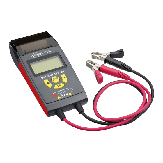
- Seite 1 Bedienungsanleitung V7548 Batterietester und Ladesystem-Prüfgerät Lieferumfang: Der Batterie-Tester V7548 wird mit einer Ersatzrolle (V7548-1) geliefert. www.vigor-equipment.com VIGOR GmbH|Am Langen Siepen 13-15|42857 Remscheid|GERMANY...
-
Seite 2: Inhaltsverzeichnis
Inhaltsverzeichnis 1) Zu Ihrer Information ..............................Seite 3 1. Allgemeine Informationen ..........................Seite 3 2. Symbolerklärung ............................... Seite 3 2) Zu Ihrer Sicherheit 1. Allgemeines 2. Verantwortung des Betreibers......................... Seite 4 3. Bestimmungsgemäße Verwendung ....................... Seite 4 4. Gefahren die vom Gerät ausgehen ......................Seite 4 5. -
Seite 3: Zu Ihrer Information
Zu Ihrer Information 1. Allgemeine Informationen 2. Symbolerklärung ACHTUNG: • Zum bestimmungsgemäßen Gebrauch des Schenken Sie diesen Symbolen höchste Aufmerksamkeit! VIGOR Batterie-Testers gehört die vollständige Beachtung aller Sicherheitshinweise und Betriebsanleitung lesen! Informationen in dieser Betriebs anleitung. Der Betreiber ist verpflichtet die •... -
Seite 4: Allgemeines
Zu Ihrer Sicherheit 1. Allgemeines Durch einfache Bedienung, präziser Ablesung, kompletten Funktionen, liefert der VIGOR Batterie-Tester Der VIGOR Batterie-Tester ist zum Zeitpunkt seiner Entwicklung die Messwerte durch ein großes LCD und gibt Hinweise und Fertigung nach geltenden, anerkannten Regeln der durch Ton und LED´s während der Überprüfung. -
Seite 5: Internationales Elektrisches Symbol
Zu Ihrer Sicherheit Der VIGOR Batterie-Tester wurde in Anlehnung der 6. Internationales elektrisches Symbol Sicherheitsnorm IEC/EN61010-1 entwickelt und hergestellt. Und erfüllt die Kategorie CAT III 600V. (1) Der Batterie-Tester dient zur 12V und 24V Batterie- Analyse, Testen des Aufladesystems und Prüfung der Anlasserprüfung. -
Seite 6: Aufbau Des Messgeräts
<ENTER> : auswählen, eingeben, testen rote Klemme: positiver Anschluss Tasten schwarze Klemme: negativer Anschluss Optionales Zubehör: V7548-1 Ersatzrolle 2. Funktionsanweisungen BITTE BEACHTEN SIE: Es wird empfohlen, einen genauen Test 2.1 Einstellung des Akkuspannungsmodus durchzuführen, solange CCA verfügbar und sichtbar ist, da... -
Seite 7: Betriebsverfahren
Aufbau und Funktion 2.4 Betriebsverfahren A. Schnelltest (Quick test) (1) Verbinden Sie die rote Klemme mit dem Pluspol und die (5) Drücken Sie entsprechend den auf der Batterie schwarze mit dem Minuspol. Achten Sie darauf, dass alle angezeigten Kapazitätswerten die Taste < ><... - Seite 8 Aufbau und Funktion B. Genauer Test (Accurate test) (1) Verbinden Sie die rote Klemme mit dem Pluspol und die (6) Drücken Sie entsprechend dem Etikett auf der Batterie die schwarze mit dem Minuspol. Achten Sie darauf, dass alle Taste < ><...
-
Seite 9: Anweisung Des Testergebnisses
Aufbau und Funktion 2.5 Anweisung des Testergebnisses Ersetzen vorschlagen (Suggest Replace) Normal Das Ergebnis zeigt an, VRLA/ GEL/ AGM/ SLA STANDARD LSI dass die Batterie schlecht Spannung der Batterie: 12,85 V ist und noch 32 % ihrer Vollständig geladen Vollständig geladen Lebensdauer hat. -
Seite 10: Belastungstest Beim Starten
Aufbau und Funktion 3. Belastungstest beim Starten 3.3 Anweisung für den Anfahrlasttest • die niedrigste Spannung höher als 9,6 V (bei einem 24-V-System liegt der Messwert über 16 V) 3.1 Vorbereitung bedeutet, dass das Startlastsystem gut ist. Wenn der Motor in Betrieb ist, schalten Sie ihn bitte zuerst aus •... -
Seite 11: Prüfung Der Maximalen Arbeitsbelastung (Max Work Load)
Aufbau und Funktion 4. Prüfung der maximalen Arbeitsbelastung (Max work load) 5. Prüfung des Ladesystems 5.1 Vorbereitung 4.1 Vorbereitung Bitte starten Sie zunächst den Motor. Bitte starten Sie zunächst den Motor. 5.2 Bedienung 4.2 Bedienung (1) Wenn der Motor in Betrieb ist, schließen (1) Wenn der Motor in Betrieb ist, schließen Sie die rote Sie die rote Klemme an den Pluspol und Klemme an den Pluspol und die schwarze an den... -
Seite 12: Es Gibt Einige Probleme Im System
Aufbau und Funktion 5.3 Es gibt einige Probleme im System aufzurufen und Datum und Uhrzeit einzustellen Und dann kann der Benutzer die Uhr entsprechend • Wenn die Spannung höher als 15,00V ist (bei dem aktuellen Datum und der Uhrzeit einstellen. einem 24V-System liegt der Wert über 30,00V), Das Datumsformat ist JJJJ-MM-TT, das Zeitformat überprüfen Sie bitte den Spannungsregler. -
Seite 13: Ist Der Von Diesem Prüfgerät Getestete Cca-Wert Korrekt
Aufbau und Funktion 6.4 Ist der von diesem Prüfgerät getestete CCA-Wert korrekt? Die Methode dieses Testers: Die Batterie ist eigentlich CCA wird als Kontrollstandard für die Herstellung gleichbedeutend mit einem aktiven Widerstand. Also der Batterie betrachtet. Nach den gesammelten fügen wir ihm eine feste Frequenz und einen kleinen Strom Aufzeichnungen ist der getestete Wert der neuen Batterie zu und messen dann den Spannungswert. - Seite 14 Aufbau und Funktion Battery Battery NEW JIS OLD JIS NEW JIS OLD JIS 32A19L NX60-N24L 65D23L 26B17R 65D26R NS70 26B17L 65D26L NS70L 28B17R 65D31R 28B17L 65D31L N70L 28B19R NS40S 70D23R 35-60 28B19L NS40LS 70D23L 25-60 32B20R NS40 75D23R 32B20L NS40L 75D23L 32C24R 75D26R...
-
Seite 15: Vergleichstabelle Der Din/En
Aufbau und Funktion Battery Battery NEW JIS OLD JIS NEW JIS OLD JIS 34B19RS NS40ZAS 80D26R NX110-5 34B19LS NS40ZALS 80D26L NX110-5L 46B26LS 145G51L N150L 1100 48D26R 150F51R NT200-12 48D26L N50L 150F51L NT200-12L 50D20R 165G51R NS200 50D20L 165G51L NS200L 50D23R 85BR60K 170F51R NX250-12 1045... - Seite 16 Aufbau und Funktion Model Das gleiche Modell Model Das gleiche Modell 54523 54524 58521 58513 54537 54545 54801 58522 58514 54551 54580 58815 58821 54533 54577 54579 58820 58515 58527 54584 54578 58827 54590 58838 58833 88092 54827 59040 59017 59018 55040 88056 59218...
-
Seite 17: Wissen Über Die Autobatterie
Aufbau und Funktion 8. Wissen über die Autobatterie 8.3 Einige gebräuchliche Abkürzungsdefinitionen Akkustandards RC- Reserve Capacity (Leistungsreserve) 8.1 Der Innenwiderstand der verschiedenen Batterietypen ist unterschiedlich Jeder Akku ist in der Lage, durchschnittlich 25 A pro Minute zu laden und hält die niedrigsten 10,5 V mehr oder weniger bei Der Innenwiderstand ist aufgrund der unterschiedlichen 80 °F (27 °C) aufrecht. -
Seite 18: Ersatzteile
Ersatzteile • Aus Sicherheitsgründen dürfen nur Original-Ersatzteile des Herstellers verwendet werden. • Falsche oder fehlerhafte Ersatzteile können zu Beschädigungen, Fehlfunktionen oder Totalausfall des Werkzeuges führen. • Bei Verwendung nicht freigegebener Ersatzteile erlöschen sämtliche Garantie-, Service-, Schadensersatz- und Haftpflichtansprüche gegen den Hersteller oder seine Beauftragten, Händler und Vertreter. Aufbewahrung / Lagerung Das Gerät ist unter folgenden Bedingungen zu lagern und aufzubewahren: •...