Herunterladen Inhalt Inhalt Diese Seite drucken
FS FMU-AD402160M3 Schnellstartanleitung

FS FMU-AD402160M3 Schnellstartanleitung

Aktiver dwdm mux demux

Werbung

Verfügbare Sprachen

Verfügbare Sprachen

Active DWDM Mux Demux
Aktiver DWDM Mux Demux
Mux Demux DWDM Actif
Quick Start Guide
Quick-Start Anleitung
Guide de Démarrage Rapide
V1.0

Werbung

Inhaltsverzeichnis
loading

Inhaltszusammenfassung für FS FMU-AD402160M3

  • Seite 1 Active DWDM Mux Demux Aktiver DWDM Mux Demux Mux Demux DWDM Actif Quick Start Guide V1.0 Quick-Start Anleitung Guide de Démarrage Rapide...
  • Seite 2 Multiplexing up to 40 channels over one ber pair, it increases the bandwidth, capacity and maximizes the usefulness of ber. A visual con rmation via LEDs shows that each channel and line are set up correctly. LINE FMU-AD402160M3 132179 PWR1 PWR2 1310...
  • Seite 3: Hardware Overview

    Hardware Overview Front Panel Ports LINE C21-C60 LINE FMU-AD402160M3 132179 PWR1 PWR2 1310 1310nm Ports Port Type Description LINE Line side port. 1% (2%, 3%, 5% can be customized) service signal monitoring Port. LC/UPC Optical supervisory channel. C21-C60 Mux Demux channel ports.
  • Seite 4 Back Panel Controller Module Power Supplies SFP1 ETH1 RESET SFP2 ETH2 Console 100VAC-240VAC/50-60HZ/2A Max 100VAC-240VAC/50-60HZ/2A Max Back Panel Ports SFP RJ45 SFP1 ETH1 RESET SFP2 ETH2 Console Ports Description SFP ports for 1G connection. RJ45 RJ45 ports for 10/100BASE-T Ethernet connection. Back Panel Button SFP1 ETH1...
  • Seite 5 Back Panel LEDs SFP1 ETH1 RESET SFP2 ETH2 Console 100VAC-240VAC/50-60HZ/2A Max 100VAC-240VAC/50-60HZ/2A Max Ports Status Description Solid Green The fan works properly. The fan is powered o . Solid Green The controller module works properly. The controller module is powered o . Blinking Green The controller module system works properly.
  • Seite 6 Installing Installing the Cable Management 1. Install ve cable rings on the cable rack. 2. Attach the cable manager to the front of the Mux Demux with plastic rivets.
  • Seite 7: Rack Mounting

    Rack Mounting 1. Place the Mux Demux on the rack. 2. Install and tighten the panel with 4 sets of screws. Installing the Ground Wire 1. Use gaskets and screws to x the ground plate to the fan at the end of the Mux Demux. 2.
  • Seite 8 Connecting the Power Cord 1. Plug the AC power cord into the power port on the back of the Mux Demux. 2. Connect the other end of the power cord to an AC power source. WARNING: Do not install power cables while the power is on. Connecting the Channel Ports 1.
  • Seite 9 Connecting the RJ45 Ports 1. Connect the ethernet cable to the RJ45 port on the Mux Demux. 2. Connect the other end of ethernet cable to the computer for WEB management. Connecting the SFP Ports 1. Plug the compatible SFP transceiver into the SFP port. 2.
  • Seite 10 Step4: WEB management and monitor the tra c of each channel online. Monitor Online 192.168.100.127/#/logln?redlrect=%2Fnetwork-element User Name Active Mux Demux Password Reset Login Copyright © 2021 by FS.COM All Rights Reserved. Monitor Online 192.168.100.127/#/system/network-element Avtive Mux Demux Monitoring interface Admin IP Con g English Logout...
  • Seite 11: Change Password

    Admin IP Con g English Logout Change Password Refresh Normal Alarm No Signal LINE FMU-AD402160M3 132179 PWR1 PWR2 1310 Change Password × Please enter a new user name *New User Name Please enter a new user Password *New Password Please enter a new user Password agian...
  • Seite 12 Admin IP Con g English Logout IP Con g Refresh Normal Alarm No Signal LINE FMU-AD402160M3 132179 PWR1 PWR2 1310 IP Con g × Please enter an IP Please enter a gateway *Gateway Please enter a subnet mask *Subnet mask...
  • Seite 13 Step4: Click "Apply" to complete the modi cation. Avtive Mux Demux Monitoring interface admin IP Con g English Logout Refresh Normal Alarm No Signal LINE FMU-AD402160M3 132179 PWR1 PWR2 1310 Edit Refresh Normal Alarm No Signal Channel TX Current Power(dBm)
  • Seite 14: Online Resources

    Product Warranty FS ensures our customers that any damage or faulty items due to our workmanship, we will o er a free return within 30 Days from the day you receive your goods. This excludes any custom made items or tailored solutions.
  • Seite 15 Durch das Multiplexen von bis zu 40 Kanälen über ein Glasfaserpaar wird die Bandbreite und Kapazität erhöht und der Nutzen der Glasfaser maximiert. Eine visuelle Bestätigung über LEDs zeigt an, dass jeder Kanal und jede Linie korrekt eingerichtet sind. LINE FMU-AD402160M3 132179 PWR1 PWR2 1310 FMU-AD402160M3 Zubehör...
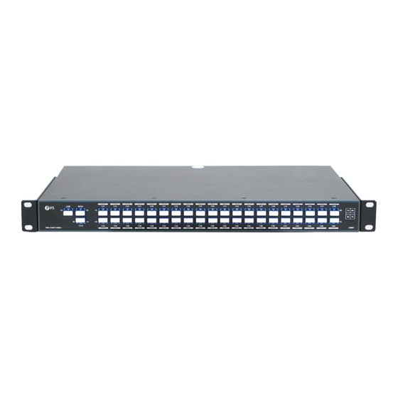
  • Seite 16: Hardware-Übersicht

    Hardware-Übersicht Ports an der Vorderseite LINE C21-C60 LINE FMU-AD402160M3 132179 PWR1 PWR2 1310 1310nm Ports Port-Typ Beschreibung LINE Leitungsseitiger Port. 1% (2%, 3%, 5% können individuell angepasst werden) Dienstsignalüberwachung Port. LC/UPC Optischer Überwachungskanal. C21-C60 Mux Demux Channel-Ports. 1310NM 1310nm Service Erweiterung Port, Kanalbandbreite ±50nm.
  • Seite 17 Rückseite Lüfter Controller-Modul Stromversorgung SFP1 ETH1 RESET SFP2 ETH2 Console 100VAC-240VAC/50-60HZ/2A Max 100VAC-240VAC/50-60HZ/2A Max Ports and der Rückseite SFP RJ45 SFP1 ETH1 RESET SFP2 ETH2 Console Ports Beschreibung SFP-Ports für 1G-Verbindungen. RJ45 RJ45-Ports für 10/100BASE-T-Ethernet-Anschluss. Tasten an der Rückseite SFP1 ETH1 RESET SFP2...
  • Seite 18: Leds An Der Rückseite

    LEDs an der Rückseite SFP1 ETH1 RESET SFP2 ETH2 Console 100VAC-240VAC/50-60HZ/2A Max 100VAC-240VAC/50-60HZ/2A Max Ports Status Beschreibung Grün Der Lüfter funktioniert ordnungsgemäß. Der Lüfter ist ausgeschaltet. Grün Das Controller-Modul arbeitet ordnungsgemäß. Das Controller-Modul ist ausgeschaltet. Blinkend Grün Das Controller-Modul-System funktioniert ordnungsgemäß. Das Controller-Modul-System ist beschädigt.
  • Seite 19: Installation

    Installation Installation des Kabelrangierpanels 1. Bringen Sie fünf Kabelfünrungsbügel am Rangierpanel an. 2. Befestigen Sie das Rangierpanel mit Kunststo nieten an der Vorderseite des Mux Demux.
  • Seite 20: Installation Des Erdungskabels

    Rack-Montage 1. Setzen Sie den Mux Demux auf das Rack. 2. Installieren Sie das Panel und ziehen Sie es mit 4 Schraubensätzen fest. Installation des Erdungskabels 1. Verwenden Sie Dichtungen und Schrauben, um die Erdungsplatte am Lüfter am Ende des Mux Demux zu befestigen.
  • Seite 21: Anschluss Der Channel-Ports

    Anschluss des Netzkabels 1. Stecken Sie das Netzkabel in den Port auf der Rückseite des Mux Demux. 2. Schließen Sie das andere Ende des Netzkabels an eine Netzstromquelle an. ACHTUNG: Schließen Sie das Netzkabel nicht an, wenn das Gerät eingeschaltet ist. Anschluss der Channel-Ports 1.
  • Seite 22: Anschluss Der Rj45-Ports

    Anschluss der RJ45-Ports 1. Schließen Sie das Ethernet-Kabel an den RJ45-Port des Mux Demux an. 2. Schließen Sie das andere Ende des Ethernet-Kabels an den Computer für das WEB-Management an. Anschluss der SFP-Ports 1. Stecken Sie den kompatiblen SFP-Transceiver in den SFP-Port. 2.
  • Seite 23 Schritt 4: Rufen Sie die WEB-Verwaltung auf und überwachen Sie den Datenverkehr der einzelnen Kanäle online. Monitor Online 192.168.100.127/#/logln?redlrect=%2Fnetwork-element User Name Active Mux Demux Password Reset Login Copyright © 2021 by FS.COM All Rights Reserved. Monitor Online 192.168.100.127/#/system/network-element Avtive Mux Demux Monitoring interface Admin IP Con g English Logout Refresh...
  • Seite 24: Change Password

    Admin IP Con g English Logout Change Password Refresh Normal Alarm No Signal LINE FMU-AD402160M3 132179 PWR1 PWR2 1310 Change Password × Please enter a new user name *New User Name Please enter a new user Password *New Password Please enter a new user Password agian...
  • Seite 25 Admin IP Con g English Logout IP Con g Refresh Normal Alarm No Signal LINE FMU-AD402160M3 132179 PWR1 PWR2 1310 IP Con g × Please enter an IP Please enter a gateway *Gateway Please enter a subnet mask *Subnet mask...
  • Seite 26 Schritt 4: Klicken Sie auf "Apply", um die Änderung abzuschließen. Avtive Mux Demux Monitoring interface admin IP Con g English Logout Refresh Normal Alarm No Signal LINE FMU-AD402160M3 132179 PWR1 PWR2 1310 Edit Refresh Normal Alarm No Signal Channel TX Current Power(dBm)
  • Seite 27 Produktgarantie FS garantiert allen Kunden, dass wir bei Schäden oder fehlerhaften Artikeln, die auf unsere Verarbeitung zurückzuführen sind, eine kostenlose Rückgabe innerhalb von 30 Tagen nach Erhalt der Ware anbieten. Dies gilt nicht für maßgefertigte Artikel oder maßgeschneiderte Lösungen.
  • Seite 28 Multiplexant jusqu'à 40 canaux sur une paire de bres, il augmente la largeur de bande, la capacité et maximise l'utilité de la bre. Une con rmation visuelle via les indicateurs LED indique que chaque canal et chaque ligne sont correctement con gurés. LINE FMU-AD402160M3 132179 PWR1 PWR2 1310...
  • Seite 29: Aperçu Du Matériel

    Aperçu du Matériel Ports du Panneau Frontal LINE C21-C60 LINE FMU-AD402160M3 132179 PWR1 PWR2 1310 1310nm Ports Type de Port Description LINE Port côté ligne. Port de surveillance du signal de service de 1 % (2%, 3%, 5% peuvent être personnalisés).
  • Seite 30: Panneau Arrière

    Panneau Arrière Ventilateur Contrôleur Alimentations SFP1 ETH1 RESET SFP2 ETH2 Console 100VAC-240VAC/50-60HZ/2A Max 100VAC-240VAC/50-60HZ/2A Max Ports du Panneau Arrière SFP RJ45 SFP1 ETH1 RESET SFP2 ETH2 Console Ports Description Ports SFP pour connexion 1G. RJ45 Ports RJ45 pour connexion Ethernet 10/100BASE-T. Bouton du Panneau Arrière SFP1 ETH1...
  • Seite 31 Indicateur LED du Panneau Arrière SFP1 ETH1 RESET SFP2 ETH2 Console 100VAC-240VAC/50-60HZ/2A Max 100VAC-240VAC/50-60HZ/2A Max Ports Statut Description Vert Le ventilateur fonctionne correctement. Éteint Le ventilateur est hors tension. Vert Le module contrôleur fonctionne correctement. Éteint Le module contrôleur est hors tension. Vert Clignotant Le système de modules de contrôle fonctionne correctement.
  • Seite 32 Installation Installation du Gestionnaire des Câbles 1. Installez cinq anneaux de câble sur le support de câble. 2. Fixez le gestionnaire de câbles à la partie frontale du Mux Demux avec des rivets en plastique.
  • Seite 33 Montage sur Rack 1. Placez le Mux Demux sur le rack. 2. Installez et xez le panneau à l'aide de 4 jeux de vis. Installation du Fil de Mise à la Terre 1. Utilisez des joints et vis pour xer la plaque de mise à la terre au ventilateur à l'extrémité du Mux Demux.
  • Seite 34: Connexion Du Câble D'alimentation

    Connexion du Câble d'Alimentation 1. Branchez le câble d'alimentation CA dans le port d'alimentation situé à l'arrière du Mux Demux. 2. Connectez l'autre extrémité du câble d'alimentation à une source de courant alternatif. ATTENTION: Ne pas installer les câbles d'alimentation lorsque l'appareil est sous tension. Connexion des Ports de Canaux 1.
  • Seite 35 Connexion des Ports RJ45 1. Connectez le câble Ethernet au port RJ45 du Mux Demux. 2. Connectez l'autre extrémité du câble Ethernet à l'ordinateur pour la gestion du Web. Connexion des Ports SFP 1. Branchez le module SFP compatible dans le port SFP. 2.
  • Seite 36 Étape 4 : Gestion du WEB et suivi du tra c de chaque canal en ligne. Monitor Online 192.168.100.127/#/logln?redlrect=%2Fnetwork-element User Name Active Mux Demux Password Reset Login Copyright © 2021 by FS.COM All Rights Reserved. Monitor Online 192.168.100.127/#/system/network-element Avtive Mux Demux Monitoring interface Admin IP Con g English Logout...
  • Seite 37 Admin IP Con g English Logout Change Password Refresh Normal Alarm No Signal LINE FMU-AD402160M3 132179 PWR1 PWR2 1310 Change Password × Please enter a new user name *New User Name Please enter a new user Password *New Password Please enter a new user Password agian...
  • Seite 38 Admin IP Con g English Logout IP Con g Refresh Normal Alarm No Signal LINE FMU-AD402160M3 132179 PWR1 PWR2 1310 IP Con g × Please enter an IP Please enter a gateway *Gateway Please enter a subnet mask *Subnet mask...
  • Seite 39 Étape 4 : Cliquez sur "Apply" pour terminer la modi cation Avtive Mux Demux Monitoring interface admin IP Con g English Logout Refresh Normal Alarm No Signal LINE FMU-AD402160M3 132179 PWR1 PWR2 1310 Edit Refresh Normal Alarm No Signal Channel TX Current Power(dBm)
  • Seite 40: Garantie Du Produit

    Garantie du Produit FS garantit à ses clients que tout article endommagé ou défectueux dû à sa fabrication pourra être retourné gratuitement dans un délai de 30 jours à compter de la date de réception de la marchandise. Cela exclut les articles fabriqués sur mesure ou les solutions personnalisées.
  • Seite 41: Compliance Information

    Any changes or modi cations not expressly approved by the grantee of this device could void the user's authority to operate the equipment. Responsible party (only for FCC matter) FS.COM Inc. 380 Centerpoint Blvd, New Castle, DE 19720, United States https://www.fs.com...
  • Seite 42 Die FS.COM GmbH erklärt hiermit, dass dieses Gerät mit der Richtlinie 2014/30/EU und 2014/35/EU konform ist. Eine Kopie der EU-Konformitätserklärung nden Sie unter www.fs.com/de/company/quality_control.html. FS.COM GmbH déclare par la présente que cet appareil est conforme à la Directive 2014/30/UE et 2014/35/UE. Une copie de la Déclaration UE de Conformité est disponible sur https://www.fs.com/fr/company/quality_control.html FS.COM LIMITED...

Inhaltsverzeichnis