Infraworld VITALlight Montage- Und Gebrauchsanweisungen
Inhaltsverzeichnis
Verfügbare Sprachen
Verfügbare Sprachen
G EBRAUCHS AN WEISUN G
TECHNISCHE DATEN:
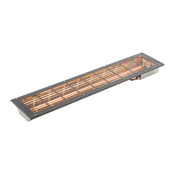
VITALlight-IPX4-Infrarotstrahler
Typ:
Einbauart: Gerade
Art. Nr.:
A6082 - 500 W (Abdeckgitter rot)
A6083 - 500 W (Abdeckgitter anthrazit)
Spannung:
230 V~, 50 Hz
Stromstärke:
16 A
Leistung:
500 W
Gerätemaße (HBT):
795 x 180 x 50 mm
Einbaumaße (HBT):
770 x 150 x 55 mm
Technische Änderungen vorbehalten
Tel.: +43 7683 5022 / E-Mail: office@tpi.co.at / Web: www.infraworld.at
MO NT AGE- UN D
D e u t sc h
TPI GmbH, Rieglerstr. 21, 4873 Frankenburg, Austria
Elektroanschluss
gerader Einbau
Einbauart: Ecke
A6084 - 500 W (Abdeckgitter rot)
A6085 - 500 W (Abdeckgitter anthrazit)
770 x 150 x 80 mm
Version: 08/2021
Elektroanschluss
Eckeinbau
DE
EN
FR
NL
IT
Inhaltsverzeichnis

Verwandte Anleitungen für Infraworld VITALlight

Inhaltszusammenfassung für Infraworld VITALlight
- Seite 1 795 x 180 x 50 mm Einbaumaße (HBT): 770 x 150 x 55 mm 770 x 150 x 80 mm Technische Änderungen vorbehalten TPI GmbH, Rieglerstr. 21, 4873 Frankenburg, Austria Tel.: +43 7683 5022 / E-Mail: office@tpi.co.at / Web: www.infraworld.at...
-
Seite 2: Sicherheitshinweise
SICHERHEITSHINWEISE: • Achtung: Abdecken des Heizers oder Infrarot-Emitters verursacht Brand- gefahr! • Infrarotkabinen mit VITALlight-IPX4-Infrarotstrahler nicht länger als ca. 10 - 15 Min. benutzen (je nach körperlicher Verfassung). • Empfohlener Abstand Strahler/Körper von ca. 10 cm. • Vermeiden Sie eine Dauerbestrahlung der Augen und achten Sie auf die Einhaltung des direkten Abstandes Strahler/Auge von ca. - Seite 3 SICHERHEITSHINWEISE: • Die Montage und der Anschluss an das Steuergerät muss nach Anschluss- schema erfolgen. • Bevor der Strahler über das Steuergerät in Betrieb genommen wird, muss überprüft werden, ob alle Steckverbindungen lösungssicher verbunden sind. • Die Vorschriften für eine Montage in eine Infrarotkabine oder Sauna, nach EN 60335-2-53, sind zu beachten.
- Seite 4 MONTAGEHINWEISE: Wichtig: Vor Inbetriebnahme, die Transportverpackung zum Schutz der Infrarotlampe entfernen. Das Abdeck- gitter des Strahlers muß dazu abgeschraubt werden (siehe Abb. 1). Entfernen Sie die Schaumstoff- Transportverpackung (siehe Abb. 2). Das Abdeckgitter anschließend wieder verschrauben. Achtung: Den Strahlerglasstab nicht mit den Fingern berühren! 2.
- Seite 5 Abb. 5 - gerader Einbau Abb. 6 - Eckeinbau...
-
Seite 6: Einbaumöglichkeiten
EINBAUMÖGLICHKEITEN: Mindestabstände: Bei dem Einbau müssen die Abstände, wie in den nachfolgenden Skizzen angeführt, eingehalten werden. Einbau senkrecht: - Der Mindestabstand von der Strahleroberkante zur Kabinendecke muss mindestens 7 cm betragen (siehe Abb. 8). - Von der Strahlerunterkante zur Sitzbank muss ein Abstand von mindestens 5 cm eingehalten werden (siehe Abb.