Axis Communications P1368-E Installationsanleitung
Vorschau ausblenden
Andere Handbücher für P1368-E:
- Benutzerhandbuch (28 Seiten) ,
- Benutzerhandbuch (54 Seiten)
Inhaltsverzeichnis
Verfügbare Sprachen
Verfügbare Sprachen
Quicklinks
Inhaltsverzeichnis

Verwandte Anleitungen für Axis Communications P1368-E


Inhaltszusammenfassung für Axis Communications P1368-E
- Seite 3 English France: Français Deutschland: Deutsch Italia: Italiano España: Español 日本: 日本語 中文: 简体中文...
-
Seite 7: Inhaltsverzeichnis
AXIS P1368-E Network Camera Package contents .......... - Seite 8 AXIS P1368-E Network Camera Tasten ............
-
Seite 47: Lieferumfang
AXIS P1368-E Network Camera Lieferumfang • AXIS P1368-E Netzwerk-Kamera • 4-poliger E/A-Anschlussblock für den Anschluss externer Geräte • 2-poliger RS485/422-Anschlussblock (2x) • Wandhalterung • Torx T20-Schraubendreher • Torx T30-Schraubenset • RJ-45-Montagewerkzeug • IK10-Werkzeug • Antikondensationsbeutel • Gedruckte Dokumente Installationsanleitung (dieses Dokument) Zusätzliche Etiketten mit der Seriennummer (2x) -
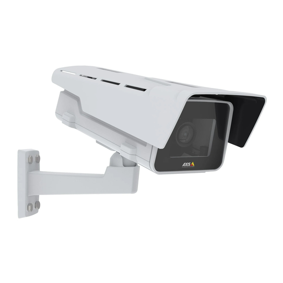
Seite 48: Produktübersicht
AXIS P1368-E Network Camera Produktübersicht Wetterschutz Obere Abdeckung Fenster Einbruchalarmmagnet Sicherheitsdraht Kabelbinderverankerung IK10-Werkzeug Einbruchalarmsensor Kabelabdeckung 10 Gefederte Rändelschrauben (4x) 11 Optisches Gerät 12 Objektiv HINWEIS HINWEIS HINWEIS Heben Sie das Produkt nicht in die Kabelabdeckung hinein. - Seite 49 AXIS P1368-E Network Camera 13 Status LED 14 Netzwerk LED 15 Netz-LED 16 microSD-Kartensteckplatz 17 E/A-Anschluss 18 RS485/422-Anschluss 19 Steuertaste 20 Netzwerkanschluss (PoE) 21 Audioausgang 22 Audioeingang 23 Kabeldichtung M20 (2x) 24 Blendenanschluss...
-
Seite 50: Installieren Des Produkts
AXIS P1368-E Network Camera Installieren des Produkts Die Hardware installieren HINWEIS HINWEIS HINWEIS • Aufgrund örtlicher Vorschriften oder der Umgebungsbedingungen und elektrischen Bedingungen, unter denen das Produkt verwendet wird, kann ein abgeschirmtes Netzwerkkabel (STP) empfehlenswert oder notwendig sein. Alle Netzwerkkabel des Produkts, die im Außenbereich oder in anspruchsvollen elektrischen Umgebungen verlegt... - Seite 51 AXIS P1368-E Network Camera HINWEIS HINWEIS HINWEIS • Wird mehr als ein Kabel verwendet, muss jedes Kabel durch eine separate Kabeldichtung geführt werden. • Öffnen Sie bei den verwendeten Kabeldichtungen nur ein Loch. Wenn eine Kabeldichtung eingerissen ist, ersetzen Sie diese durch eine neue. Wenn eine Kabeldichtung geöffnet bleibt oder eine eingerissene Kabeldichtung verwendet wird, kann Wasser eindringen und das Produkt beschädigen.
- Seite 52 AXIS P1368-E Network Camera 4. Ziehen Sie das Netzwerkkabel ein wenig zurück, bis die Kabeldichtung bündig um das Kabel sitzt. HINWEIS HINWEIS HINWEIS Wird das Kabel nicht zurückgezogen, kann Wasser eindringen und das Produkt beschädigen. 5. Vergewissern Sie sich, dass die Kabeldichtung ordnungsgemäß sitzt.
- Seite 53 AXIS P1368-E Network Camera Untere Abdeckung Schraube T20 (4x) Wandhalterung Einstellschraube T30 für Halterung 7. Setzen Sie die untere Abdeckung auf die Wandhalterung und ziehen Sie die Schrauben an (Drehmoment 2 Nm). 8. Schließen Sie ggf. externe Eingabe-/Ausgabegeräte oder Audiogeräte an die Kamera an.
- Seite 54 AXIS P1368-E Network Camera 9. Wenn Sie eine SD-Karte als lokalen Speicher verwenden, schieben Sie die Karte in den SD-Karteneinschub der Kamera. 10. Schließen Sie das Netzwerkkabel an. 11. Vergewissern Sie sich, dass die Kamera LEDs den richtigen Betriebszustand anzeigen.
- Seite 55 AXIS P1368-E Network Camera Sicherheitshaken Antikondensationsbeutel 14. Entfernen Sie die Plastikschutzhülle des Antikondensationsbeutels. 15. Entfernen Sie den Schutzstreifen von der Klebefläche und bringen Sie den Antikondensationsbeutel an der oberen Abdeckung an. 16. Schließen Sie das Gehäuse. Ziehen Sie die Schrauben der unteren Abdeckung im Wechsel jeweils wenige Umdrehungen an, bis sie fest sitzen (Drehmoment 1,5 Nm).
-
Seite 56: Einrichten Des Corridor Formats
AXIS P1368-E Network Camera Einrichten des Corridor Formats Feststellschraube (2x) Optisches Gerät 1. Lösen Sie beide Feststellschrauben. 2. Drehen Sie das optische Gerät. 3. Ziehen Sie die Feststellschrauben an. 4. Rufen Sie auf der Produktwebseite die Registerkarte Stream auf und drehen Sie die... -
Seite 57: Positionieren Des Objektivs Für Ik10
AXIS P1368-E Network Camera Positionieren des Objektivs für IK10 IK10-Werkzeug Optisches Gerät Gefederte Rändelschrauben (4x) 1. Stellen Sie das Objektiv auf die weiteste Position. 2. Bringen Sie das IK10-Werkzeug an der unteren Abdeckung an. 3. Lösen Sie die gefederten Rändelschrauben. - Seite 58 AXIS P1368-E Network Camera Wichtig Das Zurücksetzen auf die Werkseinstellungen sollte mit Vorsicht erfolgen. Beim Zurücksetzen auf die Werkseinstellungen werden alle Einstellungen einschließlich der IP-Adresse zurückgesetzt. So wird das Produkt auf die werksseitigen Standardeinstellungen zurückgesetzt: 1. Trennen Sie das Produkt von der Stromversorgung.
-
Seite 59: Weitere Informationen
AXIS P1368-E Network Camera Weitere Informationen • Die aktuelle Version dieses Dokuments finden Sie auf axis.com • Das Benutzerhandbuch steht auf axis.com zur Verfügung. • Unter axis.com/support finden Sie die aktuellen Firmwareversionen für Ihr Gerät. • Nützliches Onlinetraining und Webinare finden Sie unter axis.com/academy. -
Seite 60: Technische Daten
AXIS P1368-E Network Camera Technische Daten LEDs LED-Statusanzeige Bedeutung Grün Leuchtet bei Normalbetrieb grün. Gelb Leuchtet beim Start. Blinkt beim Wiederherstellen der Einstellungen. Netzwerk LED Bedeutung Grün Leuchtet konstant bei Verbindung mit einem 10 MBit/s-Netzwerk. Blinkt bei Netzwerkaktivität. Gelb Leuchtet konstant bei Verbindung mit einem 10 MBit/s-Netzwerk. -
Seite 61: Anschlüsse
AXIS P1368-E Network Camera • Zurücksetzen des Produkts auf die Werkseinstellungen. Siehe . Anschlüsse Netzwerkanschluss RJ45-Ethernetanschluss mit Power over Ethernet (PoE). Audioanschlüsse Das Axis-Produkt ist mit den folgenden Audioanschlüssen ausgestattet: • Audioeingang – 3,5 mm, für ein Monomikrofon oder ein Monosignal (der linke Kanal wird von einem Stereosignal benutzt). - Seite 62 AXIS P1368-E Network Camera Beispiel Erdung Gleichstrom Gleichstromausgang 12 V, max. 50mA E/A als Eingang konfiguriert E/A als Ausgang konfiguriert RS485-/RS422-Anschluss Zwei 2-polige Anschlussblöcke für serielle Schnittstellen vom Typ RS485/RS422 zur Steuerung von Zusatzgeräten, beispielsweise zum Schwenken und Neigen. Der serielle Anschluss kann in den folgenden Anschlussmodi konfiguriert werden: •...
-
Seite 63: Betriebsbedingungen
AXIS P1368-E Network Camera Funktion Kon- Hinweise takt RS485B alt RX-Paar für alle Modi (kombinierter RX/TX für RS485 mit 2 RS485/422 RX(B) Leitern) RS485A alt RS485/422 RX(A) TX-Paar für RS-422 und RS-485 mit vier Leitern RS-485/RS-422 TX(B) RS-485/RS-422 TX(A) Wichtig Die maximale Kabellänge beträgt 30 m. -
Seite 65: Sicherheitsinformationen
AXIS P1368-E Network Camera Sicherheitsinformationen Gefährdungsstufen GEFAHR Weist auf eine gefährliche Situation hin, welche, falls nicht verhindert, zu Tod oder schweren Verletzungen führen kann. WARNUNG Weist auf eine gefährliche Situation hin, welche, falls nicht verhindert, zu Tod oder schweren Verletzungen führen kann. -
Seite 66: Sicherheitsanweisungen
AXIS P1368-E Network Camera Sicherheitsanweisungen HINWEIS HINWEIS HINWEIS • Das Axis Produkt muss unter Beachtung der geltenden Gesetze und Bestimmungen betrieben werden. • Axis empfiehlt, ein abgeschirmtes Netzwerk-Kabel der Kategorie CAT5e oder höher zu verwenden. • Lagern Sie das Axis Produkt in einer trockenen und belüfteten Umgebung. - Seite 107 AXIS P1368-E Network Camera 13 ステータスLED 14 ネットワークLED 15 電源LED 16 microSDカードスロット 17 I/Oコネクタ 18 RS485/422コネクタ 19 コントロールボタン 20 ネットワークコネクタ (PoE) 21 ⾳声出⼒ 22 ⾳声⼊⼒ 23 ケーブルガスケットM20 (×2) 24 アイリスコネクタ...
- Seite 127 AXIS P1368-E Network Camera 13 状态 LED 14 网络 LED 15 电源 LED 16 microSD 卡插槽 17 I/O 连接器 18 RS485/422 连接器 19 控制按钮 20 网络连接器 (PoE) 21 音频输出 22 音频输入 23 电缆垫片 M20(2 个) 24 光圈连接器...