
Verwandte Anleitungen für resideo Braukmann V5006TF


Inhaltszusammenfassung für resideo Braukmann V5006TF
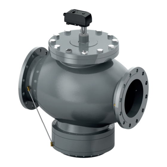
- Seite 1 Braukmann V5006TF Installation instructions Montageanleitung Kombi-QM Pressure Independent Balancing and Control Valve Kombi-QM Druckunabhängiges Strangregulier- und Regelventil...
-
Seite 2: Inhaltsverzeichnis
Actuator's features ..3 Installation Instructions . 3 External Interface ..6 Control Method ..7 Initial Setting ..7 Ratio of Value of Flow According to Flow Curve10 Manual Override... -
Seite 3: Actuator's Features
Actuator's features Installation Instructions • Proportional control Mount the valve with the arrow in the direction of the • analogue (voltage and current), PWM, 3 points and flow ON/OFF CAUTION! • Position detecting Mounting it in the wrong direction may damage the •... -
Seite 4: Operating Control
Provided the differential pressure is higher than the start up 1 Display pressure, the valve keeps flow constant at the set value. 2 Button UP 3 Button MODE 4 Button DOWN 5 Manual override Maintenance and Cleaning Operating Control Use a damp cloth to clean the actuator. To ensure that the valve is working in its operating differential pressure range. -
Seite 5: Technical Data
(SET 4); if it is bought as spare ± Power supply: 24 V AC/DC 15 % – part, the customer must inform Resideo about valve type the 50/60 Hz actuator will be mounted on, allowing Resideo's technicians Connecting cable: 18 AWG to properly set it. -
Seite 6: External Interface
2.1.7 Removal If the actuator has to be removed, follow the next procedure: Turn the connection ring between valve and actuator Remove the actuator External Interface 3.1 Wires indication 3.2 Actuator Wiring Guide Number Input Remarks Colour Black White Green Blue Feedback: Power: cable 1 - 2... -
Seite 7: Control Method
Control Method Internal control* ON/OFF Voltage signal 3 points signal Current signal PWM signal PWM Type 1: 0.1 - 5 s/Step 20ms PWM Type 2: 0.1 - 25 s/Step 100ms Note: * Flow rate can be set by buttons on the actuator and read on the 4 digits display. Initial Setting Power on display indicates ’Go-0’... - Seite 8 SET2 Voltage control signal Control with voltage signal Voltage control signal Control with voltage signal Current control signal Control with current signal Current control signal Control with current signal On/Off 24V: open. 0V: close 3 Point Floating Input 24 V open if white wire connected (3) 24 V close if green wire connected (4) Remote control Not available...
-
Seite 9: Setting Procedure
SET8 Valve open at power failure Selection Fail-CLOSE or Fail-OPEN option. Additional battery needed. Available with VA5006TF0001 Valve close at power failure SET9 Unit of SI (m Select with up/down buttons and then press “MODE“ to confirm Unit of GPM (gal/min) SET10 Linear control curve Select with up/down buttons and then press “MODE“... -
Seite 10: Ratio Of Value Of Flow According To Flow Curve10
5.2 Setting parameter SET 4: PRESETTING Valve V5006T V5006T V5006T V5006T V5006T V5006T V5006T V5006TF V5006TF V5006TF F1050 F1065 F1080 F1100 F1125 F1150 F1200LF 1200HF 1250LF 1250HF presetting flow rate presetting flow rate The presetting flow rate of valve V5006TF can be set through the parameter SET 4 of the M5006 actuator: the parameter should set between the max and min presetting flow rate of the valve. -
Seite 11: General
General 7.2 Valve-Actuator Assembly Resideo does not accept any liability for improper or wrong use of this product. Always protect the pressure regulator by using strainers upstream of the valve and, in any case, make sure water quality complies with VDI 2035 standards (Fe < 0.5 mg/kg and Cu <... -
Seite 12: Funktionsmerkmale Des Stellantriebs
Funktionsmerkmale des Einbauanleitung Stellantriebs Montieren Sie das Ventil mit dem Pfeil in • Proportionale Regelung Durchflussrichtung. • analog (Spannung und Strom), PWM, 3 Punkte und VORSICHT! EIN/AUS Durch eine falsche Montage können das System • Positionserkennung und das Ventil selbst beschädigt werden. •... -
Seite 13: Betriebssteuerung
Wenn der Differenzdruck höher als der Mindestdruck ist, hält 1 Anzeige das Ventil den Volumenstrom konstant auf dem Sollwert. 2 Nach-oben-Taste 3 Modustaste 4 Nach-unten-Taste 5 Handbetätigung Wartung und Reinigung Betriebssteuerung Verwenden Sie zum Reinigen des Stellantriebs ein Um sicherzustellen, dass sich das Ventil im Arbeitsbereich feuchtes Tuch. -
Seite 14: Technische Daten
(SET 4). Wird er als Ersatzteil gekauft, muss der Betriebsdauer: 50.000 Zyklen Kunde den Ventiltyp angeben, an dem der Stellantrieb montiert werden soll, damit ihn die Techniker von Resideo Stellsignal: 0(2)-10 V 0(4)-20 mA richtig einstellen können. Ein/Aus 3 Punkte Freigabe... -
Seite 15: Externe Schnittstelle
2.1.7 Entnahme SET1 Auswahl Eingangs-/Anzeigetyp mit Wenn der Stellantrieb demontiert werden muss, befolgen Sie internem Stellsignal die nächste Verfahrensanweisung: SET2 Auswahl Stellsignal Drehen Sie den Verbindungsring zwischen Ventil und SET3 Min. Durchflusseinstellung Stellantrieb. SET4 Max. Durchflusseinstellung Demontieren Sie den Stellantrieb. Anzeigemodus einstellen während des SET5 Betriebs... -
Seite 16: Regelmethode
Spg. Versorg.: 24 V DC (offen) Rückmeldung: Kabel 1 - 2 Auf/Zu-Signal gemeinsam 24 AC/DC 0(2) - 10 V Ein/Aus Signal: 0(4) - 20 mA (geschlossen) Kabel 1 - 3 Spg. Versorg.: Kabel 1 - 2 Rückmeldung: 3-Punkt-Regler Öffnen 24 V AC/ Schließen 24 V gemeinsam 24 AC/DC 0(2) - 10 V... -
Seite 17: Anfangs-Einstellung
Anfangs-Einstellung Bei der Inbetriebnahme wird „Go-0“ auf dem Display angezeigt und die Anfangs-Einstellung wird auf den Nullpunkt des Ventils angepasst. Drücken Sie keine Taste, da es anderenfalls zu einer falschen Nullpunkteinstellung des Ventils kommen kann. Dies führt zu fehlerhaften Volumenströmen. Der Stellantrieb verfügt über eine Sicherheitsfunktion wenn der Nullpunkt nicht automatisch erkannt wird. - Seite 18 SET5 Volumenstrom in % einstellen Auswählen mit der Nach-oben-/Nach-unten-Taste und Festlegen mit der Modustaste Anzeigeoption während des Betriebs: „St“ ermöglicht das Unter „flow rate“ eingestellter Anzeigen des vom Regler benötigten Volumenstromwerts; Volumenstrom „Fd“ ermöglicht das Anzeigen des aktuellen vom Ventil ausgegebenen Volumenstromwerts (die progressive Aktueller Volumenstrom in % Änderung der Volumenstromwerte wird während der...
-
Seite 19: Vorgehensweise Zur Einstellung
5.1 Vorgehensweise zur Einstellung SET 9 SET 4 SET 2 SET 10 Andere Parameter können bei Bedarf ohne einen Präferenzpfad eingestellt werden. 5.2 Einstellung Parameter SET 4: VOREINSTELLUNG Ventil V5006T V5006T V5006T V5006T V5006T V5006T V5006TF V5006TF V5006TF V5006TF F1050 F1065 F1080 F1100... -
Seite 20: Handbetätigung
Zum erneuten Zusammenbau des Stellantriebs dieselbe Verfahrensanweisung im Abschnitt „MONTAGE“ befolgen. 7.2 Ventil-Stellantrieb-Baugruppe Allgemeines Resideo lehnt jegliche Haftung für die unsachgemäße oder fehlerhafte Nutzung diese Produkts ab. Vor dem Ventil ist in der Versorgungsleitung ein Schmutzfänger vorzusehen und es muss immer sichergestellt werden, dass die Wasserqualität dem... - Seite 21 MU1H-2327GE23 R0121...
- Seite 22 Pittway Sàrl, Z.A., La Pièce 4, Ademco 1 GmbH, Hardhofweg 40, 1180 Rolle, Switzerland 74821 MOSBACH, GERMANY Phone: +49 6261 810 Fax: +49 6261 81309 © 2021 Resideo Technologies, Inc. All rights reserved. Subject to change. MU1H-2327GE23 R0121...