Herunterladen Inhalt Inhalt Diese Seite drucken
Inhaltsverzeichnis

Werbung

Verfügbare Sprachen

Verfügbare Sprachen

ACC30, ACC40
ENG Constant temperature controller
DEU Festwertregler
SLO Regulator konstantne temperature

Werbung

Inhaltsverzeichnis
loading

Inhaltszusammenfassung für ModvlvS ACC30

  • Seite 1 ACC30, ACC40 ENG Constant temperature controller DEU Festwertregler SLO Regulator konstantne temperature...
  • Seite 3: Introduction

    CONSTANT TEMPERATURE CONTROLLER ACC30, ACC40 INTRODUCTION Controllers ACC30, ACC40 are modern designed, microprocessor-driven devices made with digital and SMT technology. The controller are provided as a constant temperature controller with actuator designed for heating applications. The most common use is to control the return temperature in the boiler.
  • Seite 4: Inhaltsverzeichnis

    Contents Introduction ........................3 Appearance of the controller ..................5 Initial controller setup...................... 6 Step 1 - Language selection ................... 6 Step 2 - Hydraulic scheme selection ..............6 Step 3 - Opening of the mixing valve..............7 Graphic LCD display....................... 8 Description and design of the main display ............
  • Seite 5: Appearance Of The Controller

    USER MANUAL APPEARANCE OF THE CONTROLLER 1. Graphic display 2. Clutch for manual operation. 3. Button Return back. 4. Button Move to left, decreasing. 5. Button Menu entry, confirmation of selection. 6. Button Move to right, increasing. 7. Button Help. 8.
  • Seite 6: Initial Controller Setup

    INITIAL CONTROLLER SETUP Constant temperature controllers are equipped with an innovative solution, which allows initial setup of the controller in only three steps. When you connect the controller to the power supply for the first time, the software version is shown. Next, the first step appears on the screen. STEP 1 - LANGUAGE SELECTION Using buttons you select the required...
  • Seite 7: Step 3 - Opening Of The Mixing Valve

    STEP 3 - OPENING OF THE MIXING VALVE Press icon which indicates the proper direction of mixing valve opening direction. Between icons you can move with buttons After you selected the correct direction, the controller requires confirmation of the selection by pressing the button If you accidentally selected the wrong mixing valve opening direction, go back to reset the the selection...
  • Seite 8: Graphic Lcd Display

    GRAPHIC LCD DISPLAY All important data of controller operation are shown on the graphic LCD display. DESCRIPTION AND DESIGN OF THE MAIN DISPLAY Notifications Controller mode. and warnings. Controller mode. Temperature, protection functions and over- view of other data. Display of information on the screen: The controller mode, notifications and warnings are displayed in the upper third of the display.
  • Seite 9: Descpription Of Symbols On The Display

    DESCPRIPTION OF SYMBOLS ON THE DISPLAY CONTROLER MODE SYMBOLS Symbol Description Heating. Cooling. Automatic mode. Stand by. Manual mode. TEMPERATURE AND OTHER DATA SYMBOLS Symbol Description Measured temperature. Set point or calculated temperature. Supply temperature. Boiler temperature. Stand- pipe temperature. Stand- pipe temperature.
  • Seite 10: Symbols For Notices And Warnings

    SYMBOLS FOR NOTICES AND WARNINGS Symbol Description Notifications In case of exceeding the maximum temperature or activation of pro- tection function, the controller indicates the event with flashing symbol on the display. If the maximum temperature is no longer exceeded or if the protection function is turned off, a lited symbol indicates a recent event.
  • Seite 11: Menu Entry And Navigation

    MENU ENTRY AND NAVIGATION To enter the menu, press the button Move around the menu using the buttons , with the button you confirm your selection. By pressing the button you return to the previous screen. If some time no button is pressed, the backlight turns off or is reduced accor- ding to the setting.
  • Seite 12: Data Overview

    DATA OVERVIEW Diagrams of measured temperatures by days for last week. Diagrams of measured temperatures for current day. Output operation time counter.* Special service data. CONTROLLER PARAMETERS Basic settings. Settings for the heating circuit.* Settings for heat source.* SERVICE PARAMETERS Basic settings.
  • Seite 13: Temperature Settings

    TEMPERATURE SETTINGS In the menu only the temperatures are displayed, where you can set the set-point tempera- ture by the selected hydraulic scheme. By pressing buttons you choose the required temperature, and a new window opens: Current value of set-point temperature (numeric mode) Value of the last...
  • Seite 14: Operation Mode

    OPERATION MODE In this menu the operating mode of the controller is selected. Select the operaion mode with buttons and confirm with button Exit the settings by pressing the button Automatic operation Controller switch-off Heating or cooling operation mode selector Manual mode MANUAL MODE: This mode is used for testing the system or in case...
  • Seite 15: Basic Settings

    BASIC SETTINGS The menu is intended for language, time, date and display settings Language selection The required user language is selected by pressing buttons and confirmed with button Exit settings by pressing the button Time and date You set the exact time and date in the following manner: By pressing buttons move among...
  • Seite 16: Display Settings

    DISPLAY SETTINGS The following settings are available: Time of active screen illumination and autoexit from menu to the main screen. By pressing buttons you select and confirm required setting. A new window opens: Graphic Current value of setting symbol (Numeric value) The last confirmed value of setting Current value of...
  • Seite 17: Data Overview

    DATA OVERVIEW In this menu there are icons to access the following data on controller performance: DIAGRAMS OF MEASURED TEMPERATURES BY DAYS FOR LAST WEEK The graphical representation of the temperature profile in days, for each sensor. There are records of the temperatures for the last week of operation. DIAGRAMS OF MEASURED TEMPERATURES FOR CURRENT DAY Detailed graphic overview of temperature in current day for each sensor.
  • Seite 18: Controller Parameter And Auxiliary Tools

    SERVICE MANUAL CONTROLLER PARAMETER AND AUXILIARY TOOLS All additional settings and adjustments of controller performance are carried out by means of parameters. User-, Service- and parameters are found on the second menu screen. BASIC PARAMETERS The basic parameters are listed in one group P1 - basic parameters. Content of basic parameters is displayed as follows: Parameter mark Current parameter...
  • Seite 19 Basic parameters: Para- Function Parameter description Setting range Default meter value P1.1 TEMPERATURE ROUND You set the accuracy of displayed temperatures. 0- 0.1 °C 1- 0.2 °C 2- 0.5 °C 3- 1 °C P1.2 AUT. SHIFT OF CLOCK With the help of a calendar, the controller carries out 0- NO TO SUMMER/WINTER the automatic changeover between summer and winter...
  • Seite 20: Service Parameters

    SERVICE PARAMETERS Service parameters are arranged in groups S1 - Basic parameters, S2 - Parameters for the heating circuit. With service parameters it is possible to activate or select many additional functions and adaptations of controller performance. When you select the required para meter group in the menu, a new screen opens: Parameter mark...
  • Seite 21 By pressing buttons you mark the number which you want to modify and press the button When the number flashes you can modify it by pres- sing buttons and confirm it by pressing button When the correct code is inserted, the controller unlocks the parameters for editing and returns to the selected group of parameters.
  • Seite 22 Parameters for mixing circuit: Para- Function Parameter description Setting range Default meter value S2.1 MIN. SETPOINT Setting of minimal allowed setpoint temperature in heating 5 ÷ 70 °C TEMPERATURE IN 50 °C mode. Setpoint temperature cannot be adjusted lower as HEATING MODE with this parameter.
  • Seite 23 Para- Function Parameter description Setting range Default meter value S2.19 INITIAL VALVE Setting of initial valve movement duration when moving 0 ÷ 30 seconds MOVEMENT FROM from open position. With this setting the valve is moved OPEN POSITION to its control range and immediate controller respond at (SECONDS) startup of system.
  • Seite 24: Factory Settings

    FACTORY SETTINGS In the menu there are software tools to help with setting the controller. Restoring the controller settings are made through the selection of: RESET OF ALL CONTROLLER PARAMETERS Restores all settings of parameters P1, S1 (except S1.1) and S2. RESET OF ALL CONTROLLER SETTINGS AND RESTART INITIAL SETUP Restores all parameters to default values and starts the initial setup.
  • Seite 25: Controller Installation

    INSTALLATION MANUAL CONTROLLER INSTALLATION Install the regulator inside in a dry place, where it is not exposed to any strong electromag- netic fields. CONTROLLER’S ELECTRIC CONNECTION Each project with constant temperature controller needs to base exclusively on customer design and calculations and needs to be in compliance with valid rules and regulations.
  • Seite 26 24 English...
  • Seite 27: Technical Data

    TECHNICAL DATA General technical data - controller Dimensions (w x h x d) ..........102 x 84 x 94 mm Weight ............... ~800 g Housing ..............PC - thermoplastic Power supply ............230 V ~ , 50 Hz Consumption ............. 0,5 VA Degree of protection ..........
  • Seite 28: Disposal Of Old Electrical & Electronic Equipment

    DISPOSAL OF OLD ELECTRICAL & ELECTRONIC EQUIPMENT Discarding old electrical and electronic equipment (valid for EU member states and other European countries with organized separate waste collection). This symbol on the product or packaging means the product cannot be trea- ted as a household waste and it has to be disposed of separately via designa- ted collection facilities for old electrical and electronic equipment (OEEO).
  • Seite 29: Einleitung

    Festwertregler ACC30, ACC40 EINLEITUNG ACC30, ACC40 sind moderne mikroprozessorgesteuerte Geräte, hergestellt in digitaler SMT - Technologie. Die Festwertregler sind als Konstant-Temperatur-Regler mit Stellantrieb konzipiert für Hei- zungsanwendungen. Der häufigste Anwendungsfall ist die Rücklauftemperatur im Kessel zu steuern. Der Controller ACC40 neben Steuerung der Stellantrieb, steuert auch die Umwälzpumpe.
  • Seite 30 Inhalt Einleitung ........................29 Beschreibung des Reglers ..................... 31 Reglereinstellung bei der Erstinbetriebnahme..............32 1. Schritt - Auswahl der Sprache ................32 2. Schritt - Auswahl des Hydraulikschemas ............32 3. Schritt - Öffnen des Mischventils ............... 33 Graphisches LCD-Display ....................34 Beschreibung und Aussehen der Hauptanzeige ...........
  • Seite 31: Beschreibung Des Reglers

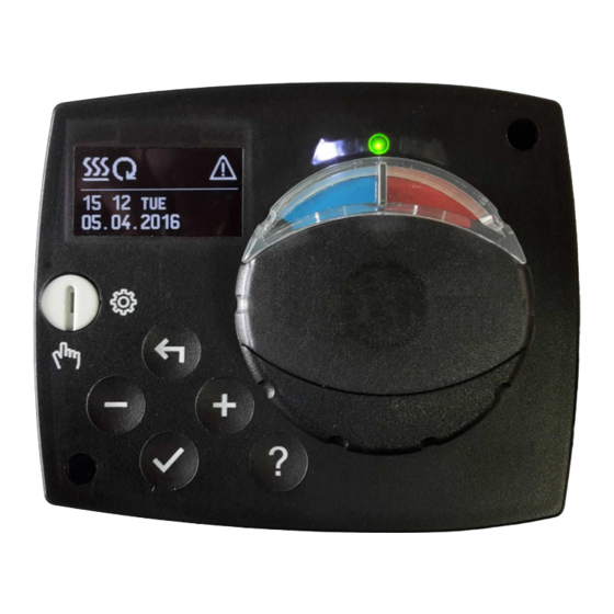
    BEDIENUNGSANLEITUNG BESCHREIBUNG DES REGLERS 1. Graphisches Display. 2. Kupplung für Manuellbetätigung. 3. Taste für Zurücksetzen. 4. Taste für Bewegung nach links oder Wertabnahme. 5. Taste für Menüanwahl oder Anwahlbestätigung. 6. Taste für bewegung nach rechts oder Wertzunahme. 7. Taste für Hilfe. 8.
  • Seite 32: Reglereinstellung Bei Der Erstinbetriebnahme

    REGLEREINSTELLUNG BEI DER ERSTINBETRIEBNAHME Die ACC30, ACC40 Festwertregler sind mit einer innovativen Lösung „Easy start“, die eine Ersteinstellung des Reglers in nur drei Schritten ermöglicht, ausgestattet. Beim ersten Anschließen des Reglers ans Netz, wird nach der Anzeige der Programmver- sion und des Logos auf dem Display, der erste Schritt zur Einstellung des Reglers ange- zeigt.
  • Seite 33: Schritt - Öffnen Des Mischventils

    3. SCHRITT - ÖFFNEN DES MISCHVENTILS Wählen Sie das richtige Drehrichtung zum Öffnen des Mischventils. Zwischen Linke und Rechte Dreh- richtung bewegt man sich mit den Tasten Das ausgewählte Drehrichtung Bestätigt man mit der Taste Der Regler verlangt eine Bestätigung der Drehrich- tung mit der Taste Haben Sie versehentlich den falschen Drehrichtung eingestellt, kehren Sie mit der Taste...
  • Seite 34: Graphisches Lcd-Display

    GRAPHISCHES LCD-DISPLAY Alle wichtigen Daten sind auf dem LCD Display ersichtlich. BESCHREIBUNG UND AUSSEHEN DER HAUPTANZEIGE Meldungen Warnungen. Betriebsart. Betriebsart. Anzeige der Temperaturen, Schutzfunktionen und anderer Angaben. Anzeige der Angaben auf dem Display: Die Betriebsart, Meldungen und Warnungen werden in dem oberen Drittel des Displays an- gezeigt.
  • Seite 35: Beschreibung Der Angezeigten Symbole Am Display

    BESCHREIBUNG DER ANGEZEIGTEN SYMBOLE AM DISPLAY SYMBOLE FÜR DARSTELLUNG DER BETRIEBSART Symbol Beschreibung Heizung. Kühlung. Automatikbetrieb. Abschaltung. Manueller Betrieb. SYMBOLE ZUR DARSTELLUNG DER TEMPERATUREN UND ANDERER DATEN Symbol Beschreibung Ist-Temperatur. Ausgerechnete Temperatur oder Soll-Temperatur. Temperatur der Wärmequelle. Kesseltemperatur. Vorlauftemperatur. Vorlauftemperatur. Rücklauftemperatur in den Kessel.
  • Seite 36: Symbole Für Warnungen Und Meldungen

    SYMBOLE FÜR WARNUNGEN UND MELDUNGEN Symbol Beschreibung Meldung Im Falle einer Überschreitung der Maximaltemperatur oder des Einschaltens der Schutzfunktion, teilt der Regler mit dem Blinken des Symbols am Display dies mit. Wenn die Maximaltemperatur nicht mehr überschritten ist oder sich die Schutzfunktion schon ausge- schaltet hat, zeigt das leuchtende Symbol den kürzlich ereigneten Vorfall an.
  • Seite 37: Einstieg Und Navigation Im Menü

    EINSTIEG UND NAVIGATION IM MENÜ Um das Menü zu öffnen, drückt man die Taste Innerhalb des Menüs bewegt man sich mit den Tasten , mit der Taste bestä- tigt man die Auswahl. Um zur vorigen Anzeige zurückzukehren, die Taste drücken. Wenn einige Zeit keine Taste gedrückt wird, schaltet sich die Displaybeleuch- tung aus bzw.
  • Seite 38: Datenkontrolle

    DATENKONTROLLE Graphische Darstellung der Temperaturen nach Tagen für die letzte Woche. Detaillierte graphische Darstellung der Temperaturen für den laufenden Tag. Betriebsstundenzähler der Steuerausgänge.* Spezielle Wartungsdaten. BENUTZERPARAMETER Allgemeine Einstellungen. Einstellungen für den Heizkreis.* Einstellungen für Energiequelle.* WARTUNGSPARAMETER Allgemeine Wartungseinstellungen. Wartungseinstellungen für den Heizkreis. Wartungseinstellungen für Energiequelle.
  • Seite 39: Temperatureinstellung

    TEMPERATUREINSTELLUNG Im Menü sind nur die Temperaturen angezeigt, bei denen man beim ausgewähltem Hyd- raulikschema die Soll-Temperatur einstellen kann. Mit den Tasten wählen wir die gewünschte Temperatur aus. Die Anzeige zur Einstellung der Soll-Temperatur erscheint: Aktueller Wert der Soll-Temperatur - numerische Darstellung Zuletzt bestätigter Graphische...
  • Seite 40: Betriebsartenwahl

    BETRIEBSARTENWAHL Unter der Gruppe wird die gewünschte Betriebsart des Reglers ausgewählt. Die gewünschte Betriebsart wählt man mit den Tasten aus und bestätigt sie mit der Taste Das Einstellen verlässt man mit dem Drücken der Taste Automatikbetrieb Ausschaltung des Reglers Umschaltung zwischen Heizung und Kühlung Manueller Betrieb Manueller Betrieb MANUELLER BETRIEB: Diese Betriebsart wird zum Test vom Heizsystem...
  • Seite 41: Grundeinstellungen

    GRUNDEINSTELLUNGEN Das Menü dient zur Einstellung der Sprache, der Zeit, des Datums und des Displays. Sprachenauswahl Die gewünschte Benutzersprache wählt man mit den Tasten aus und bestätigt sie mit der Taste Die Einstellung verlässt man mit dem Drücken der Taste Zeit und Datum Die genaue Zeit und Datum werden wie folgt einge- stellt:...
  • Seite 42: Displayeinstellung

    DISPLAYEINSTELLUNG Es stehen folgende Einstellungen zur Verfügung: Dauer der aktiven Beleuchtung des Displays und des automatischen Verlassens des Menüs Mit den Tasten wird die gewünschte Einstellung ausgewählt und bestätigt. Eine neue Anzeige erscheint: Graphisches Aktueller Einstellwert Symbol (Numerisch) Zuletzt bestätigter Einstellwert Aktueller Einstellwert (Graphisch) Werkseinstellung...
  • Seite 43: Daten Kontrolle

    DATEN KONTROLLE Im Menü befinden sich Ikonen, die Ihnen den Zugang zu folgenden Betriebsangaben des Reglers ermöglichen: DARSTELLUNG DER TEMPERATUREN NACH TAGEN FÜR DIE LETZTE WOCHE Die graphische Darstellung des Temperaturverlaufs nach Tagen, für jeden Fühler. Es werden die Temperaturen für die letzte Betriebswoche aufgezeichnet. DETAILLIERTE DARSTELLUNG DER TEMPERATUREN FÜR DEN LAUFENDEN TAG Die detaillierte graphische Darstellung des Temperaturverlaufes für den laufenden Tag, für jeden Fühler.
  • Seite 44: Reglerparameter

    WARTUNGSANLEITUNGEN REGLERPARAMETER Alle zusätzlichen Einstellungen und Anpassungen des Reglerbetriebs werden mit Hilfe der Parameter ausgeführt. Benutzer-, Wartungs- und Funktionsparameter befinden sich auf dem zweiten Menübildschirm. BENUTZERPARAMETER Die Benutzerparameter sind in die Gruppe P1 - allgemeine Einstellungen, eingeteilt. Wenn im Menü die gewünschte Parametergruppe ausgewählt wird, erscheint eine neue Anzeige: Bezeichnung Aktueller...
  • Seite 45: Allgemeine Einstellungen

    Allgemeine Einstellungen: Para- Parameterbezeichnung Beschreibung des Parameters Einstellungsbe- Übernom- meter reich mener Wert P1.1 DARSTELL. DER TEMPE- Bestimmung der Darstellung der Temperaturrundung 0- 0.1 °C RATURRUNDUNG der gemessenen Temperatur. 1- 0.2 °C 2- 0.5 °C 3- 1 °C P1.2 AUTOMATISCHER ÜBER- Mit Hilfe des Kalenders, schaltet der Regler automa- 0- NEIN GANG DER UHR AUF...
  • Seite 46: Wartungsparameter

    WARTUNGSPARAMETER Die Wartungsparameter sind in Gruppen S1 - allgemeine Einstellungen und S2 - Einstel- lungen für den Mischerkreis, eingeteilt. Mit den Wartungsparametern kann man zwischen zahlreichen Zusatzfunktionen und Anpassungen im Reglerbetrieb wählen. Wenn im Menü die gewünschte Parametergruppe ausgewählt wird, erscheint eine neue Anzeige: Bezeichnung Aktueller des Parameters...
  • Seite 47: Allgemeine Wartungseinstellungen

    Mit den Tasten stellt man sich auf die Ziffer, die verändert werden soll, und drückt die Taste . Wenn die Ziffer blinkt, kann man sie mit den Tasten verändern und mit der Taste bestätigen. Wenn der richtige code eingetragen ist, entsperrt der Regler die Parameter und Sie werden zurück zur ausgewählten Parametergruppe geleitet.
  • Seite 48: Wartungseinstellungen Für Den Mischerkreis

    Wartungseinstellungen für den Mischerkreis: Para- Parameterbezeich- Beschreibung des Parameters Einstellungsbe- Übernom- meter nung reich mener Wert S2.1 UNTERE GRENZE Eingestellt wird die minimale erlaubte Solltemperatur bei 5 ÷ 70 °C DER TEMPERA- Heizbetrieb. Die Solltemperatur kann nicht höher als mit 50 °C TUREINSTELLUNG diesem Parameter eingestellt werden.
  • Seite 49: Wartungseinstellungen Für Kessel

    Para- Parameterbezeich- Beschreibung des Parameters Einstellungsbe- Übernom- meter nung reich mener Wert S2.16 UMWÄLZPUMPE Mit dieser Einstellung wird der Unterschied zwischen den 0,4 ÷ 2,5 DES KESSELS - AB- Sensoren T2 und T1 bestimmt, unter dem die Umwälz- SCHALTUNGSTEM- pumpe des Kessels ausgeschaltet wird. PERATURUNTER- SCHIED T2-T1 (°C) S2.19...
  • Seite 50: Werkseinstellungen

    Para- Parameterbe- Beschreibung des Parameters Einstellungsbe- Übernom- meter zeichnung reich mener Wert S3.6 MAXIMALE Einstellung der maximalen Temperatur, bei der die Rege- 20 ÷ 40 °C TEMPERATUR DES lung das Mischventil vollkommen öffnet. KÜHLSYSTEMS (°C) WERKSEINSTELLUNGEN Im Menü befinden sich Softwarewerkzeuge für ein leichteres Einstellen des Reglers. Das Zurücksetzen auf die gewünschten Reglereinstellungen erfolgt mit der Auswahl von: RESET DER REGLERPARAMETER Setzt alle Parametereinstellungen P1, S1 (außer S1.1), S2 und S3 auf die Werkseinstellungen...
  • Seite 51: Montage Des Reglers

    MONTAGEANLEITUNG MONTAGE DES REGLERS Der Regler wird in einem trockenen Innenraum montiert. Die Montage in unmittelbarer Nähe von Quellen eines starken elektromagnetischen Feldes ist zu vermeiden. ELEKTRISCHER ANSCHLUSS DES REGLERS Jedes Heizregler-Projekt muss auf Berechnungen basieren und geplant sein. Das Berechnen und Planen liegt ausschließlich in Ihren Händen und muss den geltenden Regeln entsprechen.
  • Seite 52 50 Deutsch...
  • Seite 53: Technische Daten

    TECHNISCHE DATEN Technische Charakteristiken - Regler Abmessungen: ............102 x 84 x 94 mm Reglermasse ............. ~800 g Reglergehäuse ............PC - Thermoplast Spannungsversorgung ..........230 V ~ , 50 Hz Eigenverbrauch ............0,5 VA Schutzstufe ............... IP42 gem. EN 60529 Schutzklasse .............
  • Seite 54: Entsorgung Von Gebrauchten Elektrischen Und Elektronischen Geräten

    ENTSORGUNG VON GEBRAUCHTEN ELEKTRISCHEN UND ELEKTRONISCHEN GERÄTEN Entsorgung von gebrauchten elektrischen und elektronischen Geräten (Anzuwenden in den Ländern der Europäischen Union und anderen europäischen Ländern mit einem sepa- raten Sammelsystem für diese Geräte). Das Symbol auf dem Produkt oder seiner Verpackung weist darauf hin, dass dieses Produkt nicht als normaler Haushaltsabfall zu behandeln ist, sondern an einer Annahmestelle für das Recycling von elektrischen und elektronischen Geräten abgegeben werden muss.
  • Seite 55: Regulator Konstantne Temperature Acc30 In Acc40

    REGULATOR KONSTANTNE TEMPERATURE ACC30 IN ACC40 UVOD Regulatorji ACC30 in ACC40 so sodobne mikroprocesorsko vodene naprave. Izdelani so v digitalni in SMT-tehnologiji. Namenjeni so regulaciji konstantne temperature z motornim pogonom v najrazličnejših ogrevalnih aplikacijah. Najpogosteje se uporabljajo za regulacijo povratne temperature v kotel. Regulator ACC40 poleg motornega pogona krmili še obtočno črpalko.
  • Seite 56 Vsebina Uvod ..........................55 Videz regulatorja ......................57 Nastavitev regulatorja ob prvem zagonu ................ 58 1. Korak - izbira jezika .................... 58 2. Korak - izbira hdravlične sheme ................. 58 3. Korak - odpiranje mešalnega ventila ..............59 Grafični LCD-displej......................60 Opis in izgled zaslona.....................
  • Seite 57: Videz Regulatorja

    NAVODILA ZA UPORABO VIDEZ REGULATORJA 1. Grafični displej 2. Sklopka za ročno delovanje. 3. Tipka . Vrnitev nazaj. 4. Tipka . Pomik v levo, zmanjševanje. 5. Tipka . Vstop v meni, potrditev izbire. 6. Tipka . Pomik v desno. povečevanje. 7.
  • Seite 58: Nastavitev Regulatorja Ob Prvem Zagonu

    NASTAVITEV REGULATORJA OB PRVEM ZAGONU Regulator je opremljen z inovativno rešitvijo „Easy start“. ki omogoča začetno nastavitev regulatorja v samo treh korakih. Pri prvem vklopu regulatorja na omrežje, se po izpisu verzije programa in logotipa, na displeju izpiše prvi korak postopka za nastavitev regulatorja. 1.
  • Seite 59: Korak - Odpiranje Mešalnega Ventila

    3. KORAK - ODPIRANJE MEŠALNEGA VENTILA Izberemo pravilno smer odpiranja mešalnega ventila. Med smerema se pomikamo s tipkama Izbrano smer potrdimo s tipko Regulator zahteva potrditev pravilnosti izbire smeri s tipko Če smo po pomoti izbrali napačno smer se vrnemo na ponovno izbiro smeri s tipko Smer odpiranja mešalnega ventila lahko kasneje spremenimo s servisnim parametrom S1.4.
  • Seite 60: Grafični Lcd-Displej

    GRAFIČNI LCD-DISPLEJ Vse pomembne podatke o delovanju regulatorja vidimo na grafičnem LCD displeju. OPIS IN IZGLED ZASLONA Obvestila in Način delovanja. opozorila. Način delovanja. Temperature, zaščitne funkcije in prikaz drugih podatkov. Prikaz podatkov na zaslonu: Način delovanja, obvestila in opozorila se prikazujejo v zgornji tretjini zaslona. Za preklop med prikazom podatkov in prikazom hidravlične sheme uporabljamo tipko Za pregled temperatur in drugih podatkov uporabimo tipki .
  • Seite 61: Opis Grafičnih Simbolov Na Zaslonu

    OPIS GRAFIČNIH SIMBOLOV NA ZASLONU SIMBOLI ZA OPIS NAČINA DELOVANJA Simbol Opis Ogrevanje. Hlajenje. Avtomatski način delovanja. Izklop. Ročno delovanje. SIMBOLI ZA PRIKAZ TEMPERATUR IN DRUGIH PODATKOV Simbol Opis Izmerjena temperatura. Želena ali izračunana temperatura. Temperatura vira toplote. Temperatura kotla. Temperatura dvižnega voda.
  • Seite 62: Simboli Za Obvestila In Opozorila

    SIMBOLI ZA OBVESTILA IN OPOZORILA Simbol Opis Obvestilo V primeru prekoračitve maksimalne temperature nas regulator obvesti z utripanjem simbola na displeju. Če maksimalna temperatura ni več prekoračena nas na nedavni dogodek opozarja prižgani simbol. S pritiskom na tipko prikličemo zaslon za pregled obvestil. Opozorilo V primeru okvare tipala nam regulator javlja napako z utripajočim sim- bolom na displeju.
  • Seite 63: Vstop In Navigacija Po Meniju

    VSTOP IN NAVIGACIJA PO MENIJU Za vstop v meni pritisnemo tipko Po meniju se premikamo s tipkama , s tipko pa izbiro potrdimo. S pritiskom na tipko se vrnemo na prejšnji zaslon. Kadar nekaj časa ne pritisnemo nobene tipke, osvetlitev zaslona ugasne, oziroma se zmanjša na nastavljen nivo.
  • Seite 64 PREGLEDOVANJE PODATKOV Grafični prikaz temperatur po dnevih za obdobje zadnjega tedna. Detajlni grafični prikaz temperatur za tekoči dan. Števci obratovalnih ur krmilnih izhodov.* Posebni servisni podatki. UPORABNIŠKI PARAMETRI Splošne nastavitve. Nastavitve za ogrevalni krog.* Nastavitve za vire energije.* SERVISNI PARAMETRI Splošne servisne nastavitve.
  • Seite 65: Nastavitev Temperatur

    NASTAVITEV TEMPERATUR V meniju so prikazane tiste temperature, za katere lahko pri izbrani hidravlični shemi nasta- vimo želeno temperaturo. S tipkami izberemo želeno temperaturo in odpre se zaslon za nastavitev želene temperature: Trenutna vrednost želene temperature (numerični prikaz) Zadnja potrjena vrednost Grafični prikaz nastavitve nastavitve...
  • Seite 66: Izbira Načina Delovanja

    IZBIRA NAČINA DELOVANJA V meniju izberemo želen način delovanja regulatorja. S tipkama nastavimo način delovanja in ga s tipko potrdimo. Nastavitev zapustimo s tipko Avtomatski način delovanja Izklop Preklop med ogrevanjem in hlajenjem Ročno delovanje ROČNI NAČIN DELOVANJA: Ta način delovanja uporabljamo za preizkušanje regulacijskega sistema ali v primeru okvare.
  • Seite 67: Osnovne Nastavitve

    OSNOVNE NASTAVITVE Meni je namenjen za nastavitev jezika, časa, datuma in displeja. Uporabniški jezik Želeni uporabniški jezik izberemo s tipkami in ga potrdimo s tipko Nastavitev zapustimo s tipko Čas in datum Točen čas in datum nastavimo na sledeč način: S tipkami se pomikamo med posameznimi podatki.
  • Seite 68 NASTAVITEV DISPLEJA Na voljo je sledeča nastavitev: Trajanje aktivne osvetlitve in samodejnega izhoda iz menija. S tipko potrdimo želeno nastavitev. Odpre se nov zaslon: Trenutna vrednost Grafični nastavitve (numerični prikaz). simbol. Zadnja potrjena vrednost Trenutna vrednost nastavitve. nastavitve (grafični prikaz). Tovarniška vrednost.
  • Seite 69: Pregledovanje Podatkov

    PREGLEDOVANJE PODATKOV V meniju so ikone za dostop do podatkov o delovanju regulatorja: PRIKAZ TEMPERATUR ZA OBDOBJE ENEGA TEDNA Grafični prikaz poteka temperature, po dnevih, za vsako tipalo. Temperature so zabeležene za zadnji teden delovanja. DETAJLNI PRIKAZ TEMPERATUR ZA TEKOČI DAN Detajlni grafični prikaz poteka temperatur, v tekočem dnevu, za vsako tipalo.
  • Seite 70: Parametri Regulatorja In Pomožna Orodja

    NAVODILA ZA SERVISNE NASTAVITVE PARAMETRI REGULATORJA IN POMOŽNA ORODJA Vse dodatne nastavitve in prilagoditve delovanja regulatorja se izvršijo s pomočjo paramet- rov. Uporabniški, servisni in funkcijski parametri se nahajajo na drugem zaslonu menija. UPORABNIŠKI PARAMETRI Uporabniški parametri so razvrščeni v skupini P1 - splošne nastavitve. Ko v meniju izberemo želeno skupino parametrov se odpre nov zaslon: Trenutna vrednost Oznaka parametra...
  • Seite 71 Splošne nastavitve: Para- Ime parametra Opis parametra Območje nasta- Privzeta meter vitve vrednost P1.1 ZAOKROŽEVANJE PRI- Določimo na kakšno vrednost se naj zaokroži prikaz 0- 0.1 °C KAZA TEMPERATUR izmerjenih temperatur. 1- 0.2 °C 2- 0.5 °C 3- 1 °C P1.2 SAMODEJNI PREMIK Regulator, s pomočjo koledarja, izvrši samodejni...
  • Seite 72: Servisni Parametrii

    SERVISNI PARAMETRI Servisni parametri so razvrščeni v skupine S1 - splošne nastavitve, S2 - nastavitve za ogrevalni krog. S servisnimi parametri je možno izbrati med mnogimi dodatnimi funkcijami in prilagoditvami delovanja regulatorja. Ko v meniju izberemo želeno skupino parametrov se odpre nov zaslon: Oznaka Vrednost parametra...
  • Seite 73 S tipkama se postavimo na številko, ki jo želimo spremeniti in pritisnemo tipko Ko številka utripa, jo lahko spremenimo s tipkama ter jo potrdimo s tipko Ko imamo vpisano pravilno kodo, regulator odklene parametre in nas vrne v izbrano skupino parametrov. Vnos kode za odklepanje lahko zapustimo s tipko Tovarniško nastavljena koda je “0001”.
  • Seite 74 Servisne nastavitve za ogrevalni krog: Para- Ime parametra Opis parametra Območje nasta- Privzeta meter vitve vrednost S2.1 SPODNJA MEJA Nastavi se spodnja meja nastavitve želene temperature 5 ÷ 70 °C NASTAVITVE dvižnega voda, če je izbran način delovanja ogrevanje. ŽELENE TEMPERA- Želene temperature ni mogoče nastaviti nižje, kot je 50 °C TURE DVIŽNEGA...
  • Seite 75 Para- Ime parametra Opis parametra Območje nasta- Privzeta meter vitve vrednost S2.16 OBTOČNA ČRPALKA Z nastavitvijo določimo diferenco med tipaloma T2 in T1, pod 2.0 ÷ 8.0 KOTLA- IZKLOPNA katero se izklopi obtočna črpalka kotla. DIFERENCA T2-T1 (°C) S2.19 PRVI POMIK Z nastavitvijo določimo dolžino prvega impulza pri pomiku 0 ÷...
  • Seite 76: Tovarniške Nastavitve

    TOVARNIŠKE NASTAVITVE V meniju se nahajajo orodja za pomoč pri nastavitvah regulatorja. Regulator vrnamo na želene nastavitve tako, da izberemo: RESET PARAMETROV REGULATORJA Povrne vse nastavitve parametrov P1, S1 (razen S1.1) in S2 na tovarniške vrednosti. RESET REGULATORJA IN PONOVNI ZAGON PRVE NASTAVITVE Povrne vse parametre na tovarniške vrednosti in zažene nastavitev regulatorja kot ob prvem zagonu.
  • Seite 77: Navodila Za Montažo

    NAVODILA ZA MONTAŽO MONTAŽA REGULATORJA Regulator montiramo v notranjem in suhem prostoru. Izogibamo se neposredni bližini virov močnega elektromagnetnega polja. ELEKTRIČNI PRIKLOP REGULATORJA Vsak projekt z regulatorjem ACC mora temeljiti na preračunih in načrtih, ki so izključno Vaši in v skladu z veljavnimi predpisi. Slike in besedila v tem navodilu so mišljeni kot zgled in zanje izdajatelj ne prevzema odgovornosti.
  • Seite 78 76 Slovensko...
  • Seite 79: Tehnični Podatki

    TEHNIČNI PODATKI Splošni tehnični podatki - regulator Dimenzije (š x v x g) ..........102 x 84 x 94 mm Masa regulatorja ............~800 g Ohišje regulatorja ............PC - termoplast Napajalna napetost ........... 230 V ~ , 50 Hz Lastna poraba ............
  • Seite 80: Odstranjevanje Stare Električne In Elektronske Opreme

    ODSTRANJEVANJE STARE ELEKTRIČNE IN ELEKTRONSKE OPREME Odstranjevanje stare električne in elektronske opreme (Velja za države članice Evropske unije in ostale evropske države s sistemom ločenega zbiranja odpadkov). Ta simbol na izdelku ali embalaži označuje, da ga ne smete odvreči kot gos- podinjski odpadek.
  • Seite 81: Hydraulic Schemes

    HIDRAVLIČNE SHEME / HYDRAULIC SCHEMES / HYDRAULIKSCHEMAS POMEMBNO POZOR! Instalacijske sheme prikazujejo princip delovanja in ne vsebujejo vseh pomožnih in varovalnih elementov! Pri montaži je potrebno upoštevati veljavne predpise! IMPORTANT ATTENTION! Installation schemes show operation principles and do not include all auxil- iary and safety elements! Observe the regulations in force when performing installations! WICHTIG ACHTUNG! Die Installationsschemas verweisen auf das Betriebsprinzip und verfügen...
  • Seite 82 01 (ACC30) 01 (ACC40)
  • Seite 83 02 (ACC30) 02 (ACC40)
  • Seite 84 03 (ACC30) 03 (ACC40)
  • Seite 85 04 (ACC30) 04 (ACC40)
  • Seite 88 Software V1.0r0 V1.0 ©2016 We reserve the right to errors, changes and improvements without prior notice. ©2016 Wir behalten uns das Recht auf Fehler, Änderungen und Verbesserungen ohne vorherige Ankündigung. ©2016 Pridržujemo si pravico do napak, sprememb in izboljšav brez predhodne najave.

Diese Anleitung auch für:

Acc40

Inhaltsverzeichnis