Inhaltsverzeichnis
Werbung
Quicklinks
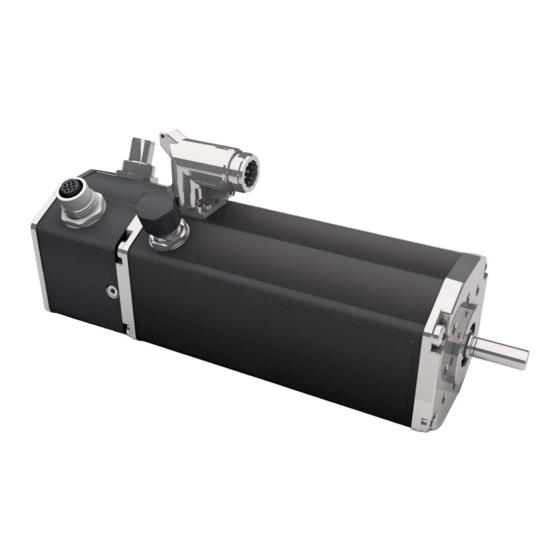
BG 65S PB
Operation manual Name
Publication Ref: 000000
Betriebsanleitung Name
Publikation Ref: 000000
Dunkermotoren GmbH | Allmendstraße 11 | D-79848 Bonndorf/ Schwarzwald
Phone +49 (0) 7703 930-0 | Fax +49 (0) 7703 930-210/ 212 | info@dunkermotoren.com
Typ:
Bezeichnung
Bezeichnung
Part No:
88566 XXXXX
88720XXXXX
Werbung
Inhaltsverzeichnis
Fehlerbehebung

Verwandte Anleitungen für Ametek dunkermotoren BG 65S PB Serie


Inhaltszusammenfassung für Ametek dunkermotoren BG 65S PB Serie
- Seite 1 BG 65S PB Typ: Part No: Bezeichnung 88566 XXXXX Bezeichnung 88720XXXXX Operation manual Name Publication Ref: 000000 Betriebsanleitung Name Publikation Ref: 000000 Dunkermotoren GmbH | Allmendstraße 11 | D-79848 Bonndorf/ Schwarzwald Phone +49 (0) 7703 930-0 | Fax +49 (0) 7703 930-210/ 212 | info@dunkermotoren.com...
-
Seite 2: Inhaltsverzeichnis
Content Inhalt 2 About this document ��������������������������������� 6 2 Über dieses Dokument������������������������������ 6 3 General description ����������������������������������� 7 3 Allgemeine Beschreibung ������������������������ 7 ............. 7 ..........7 3.1 Series 3.1 Baureihe ..........9 ... 9 3.2 Proper use 3.2 Bestimmungsgemäße Verwendung ...... - Seite 3 ... 20 ......20 8.3 Angle ajdustment motor connector 8.3 Winkellage Motorstecker ....21 ..21 8.4 Electro-magnetic compabitibiliy 8.4 Elektromagnetische Verträglichkeit ..........21 ..........21 8.5 Grounding 8.5 Erdung ......22 ....22 8.6 Power and logic supply 8.6 Leistungs- und Logikversorgung ........
- Seite 4 ........38 ........38 10.2.3.1 Configuration 10.2.3.1 Gruppierung ......39 ....... 39 10.2.3.2 Byte configuration 10.2.3.2 Byteanordnung ........40 ........40 10.2.3.3 Errorhandler 10.2.3.3 Errorhandler ......42 ......42 10.2.3.4 Motor parameter 10.2.3.4 Motorparameter ........51 ........51 10.2.4 Configuration 10.2.4 Konfiguration ......
- Seite 5 10.4.4 Example FB „DNK_DPV1“ component for 10.4.4 Beispiel Baustein FB „DNK_DPV1“ ® ........ 82 ® ......82 Siemens SIMATIC S7 für Siemens SIMATIC S7 ........87 ......... 87 10.4.5 Error codes 10.4.5 Fehlernummern ..88 ....88 10.5 DP-V0 parameter channel module 10.5 DP-V0 Parameterkanal Modul ........
-
Seite 6: About This Document
2 About this document 2 Über dieses Dokument Please read this manual carefully before installing and Lesen Sie diese Betriebsanleitung vor Anschluss und operating the motor and follow the instructions to ensure a Inbetriebnahme des Motors durch und befolgen Sie flawless operation. -
Seite 7: General Description
3 General description 3 Allgemeine Beschreibung 3�1 Series 3�1 Baureihe » Motors in the BG 65 PB range are brushless servo » Bei der Motorbaureihe BG 65S PB handelt es sich motors with an integrated motion controller and um bürstenlose DC-Servomotoren mit integriertem Profibus interface. -
Seite 8: Steuerung
Besides supporting the synchronous data exchange the Der Motor unterstützt neben dem zyklischen Daten- motor also supports (as per DP-V0), the asynchronous transfer (nach DP-V0) auch den azyklischen Daten- transfer of Data (as per DP-V1). transfer (nach DP-V1). The synchronous data are intended for the process data Die zyklischen Daten sind für die Prozessdaten vorge- and the asynchronous data for the sehen und die azyklischen Daten für die Parametrie-... -
Seite 9: Proper Use
3�2 Proper use 3�2 Bestimmungsgemäße Verwendung » The BG 65 S PB is a supplied part and may be » Der BG 65S PB ist ein Zulieferteil und darf in installed into (industrial) machinery and equipment in der beschriebenen Konfiguration in Maschinen the described configuration. -
Seite 10: Safety Instructions
4 Safety instructions 4 Sicherheitshinweise Before commissioning it is essential Vor der Inbetriebnahme sind unbedingt that the safetey instructions are read die Sicherheitshinweise zu lesen und and understood, and then observed! zu beachten. Eine Nichtbeachtung Non-obersvance can result in danger kann zu Gefahren bei Personen oder to persons or damage to the machine. -
Seite 11: Technical Data, Accessories
5 Technical data, accessories 5 Technische Daten, Zubehör 5�1 Elektrical data 5�1 Elektrische Daten BG 65S PB Non-destructive voltage range power supply/ 0 ... 58 Zerstörungsfreier Spannungsbereich Leistungsversorgung Operating voltage range power supply/ 10 ... 50 Betriebsspannungsbereich Leistungsversorgung Non-destructive voltage range logic supply/ -48 ... -
Seite 12: Load Diagram Output Shaft
5.2.1 Load diagram output shaft 5.2.1 Wellenbelastungsdiagramm The permissible shaft load (axial/ra- Die zulässigen Wellenbelastungen NOTICE HINWEIS dial) depends on the speed. Please (axial/radial) sind abhängig von der consider the following chart. In case of Drehzahl. Beachten Sie hierzu das overload the motor might fails earlier. -
Seite 13: Motor Specification
5.4 Motor specification 5.4 Motorspezifikationen Exceeding of the maximum permitted Überschreiten der maximal zulässigen NOTICE HINWEIS continious current. Dauerströme. Consequence: Kann zu Zerstörung des Antriebs The drive may be destroyed. führen. » Mind the maximum permitted » Die maximal zulässigen Dauer- continious current! ströme beachten! BG 65S x 25 PB... -
Seite 14: Optional Attachments
5�5 Optional attachments 5�5 Optionale Anbauten Worm gear Schneckengetriebe The worm gear is extremely quiet. In many applications, Die Schneckengetriebe zeichnen sich durch hohe Lauf- the gear shaft shifted by 90° compared to the motor shaft ruhe aus. Bei vielen Anwendungen ist die um 90° ge- is ideal with regard to structural aspects. -
Seite 15: Types Of Operation
6 Types of operation 6 Betriebsarten The servo motor is controlled actively by a Profibus Der Servomotor wird aktiv von einem Profibus-Master master via Profibus bus. The servo motor receives its über Profibus-Bus angesteuert. Der Servomotor er- control commands from the Profibus master via Profibus hält seine Fahrbefehle vom Profibus-Master über das network. -
Seite 16: Protective Functions
7 Protective functions 7 Schutzfunktionen The motor has several protection functions to avoid Der Motor besitzt verschiedene Schutzfunktionen, um damages by overload. Schäden durch Überbelastung zu vermeiden. Jede Each protection function is described below in detail. dieser Schutzfunktionen wird nachfolgend im Detail If a critical limit is reached the power stage is beschrieben. -
Seite 17: Over Current (I 2 T)
7�6 Over current (I 7�6 Strombegrenzung (I Logic supply is disconnected. Logikversorgung wird unterbrochen. Consequence: All calculated values Die Folge: Alle berechneten Werte, are lost, also the calculated heat input. auch der berechnete Wärmeeintrag In combination with high current e.g. gehen verloren. -
Seite 18: Voltage Controlled Braking
7�7 Voltage controlled braking 7�7 Spannungsgeregeltes Bremsen If no ballast resistor is connected and the power supply Wenn kein Ballastwiderstand vorhanden ist und exceeds 54 V, the current will be limited as much as re- die Versorgungsspannung die 54 V überschreitet, quired to prevent further power supply voltage increase. -
Seite 19: Installation
8 Installation 8 Installation Before commisioning, it is essential Vor der Inbetriebnahme sind unbedingt that the safety instructions are read die Sicherheitshinweise zu lesen und and understood, and then observed! zu beachten! Eine Nichtbeachtung Non-obersvance can result in danger to kann zu Gefahren bei Personen oder persons or damage to the machine. -
Seite 20: Motor Connector Connection
8�2 Motor connector connection 8�2 Anbindung Motorstecker During connecting of the cable with the motor note sym- Während dem Verbinden des Kabels mit dem Motor, bol H (see drawing). achten Sie auf das Symbol H (Siehe Zeichnung). 8�3 Angle ajdustment motor connector 8�3 Winkellage Motorstecker Description Pos. -
Seite 21: Electro-Magnetic Compabitibiliy
8�4 Electro-magnetic compabitibiliy 8�4 Elektromagnetische Verträglichkeit During operation of the drive respectively the entire Beim Betrieb des Motors, bzw. der gesamten system electromagnetic interference is created. Anlage entstehen elektromagnetische Without suitable protective measures, this can influence Störstrahlungen. Diese können ohne geeignete Schutz- signals in control cables and parts of the installation and maßnahmen die Signale von Steuerleitungen und An- endanger the operational reliability of the installation. -
Seite 22: Power And Logic Supply
8�5 Grounding 8�5 Erdung To comply with EMC-standards, the Zur Einhaltung der EMV-Konformität ist motor housing must be grounded. das Motorgehäuse zu erden. Generally loops must be avoided Grundsätzlich sind bei allen Erdungs- for all grounding concepts. Shielded konzepten Schleifen zu vermeiden. cables must be used for the entire Leitungsschrime sind über die ge- cable system without interruption. -
Seite 23: Mating Connector With Cable
8�6 Power and logic supply 8�6 Leistungs- und Logikversorgung Plug: Stecker: Round plug M16, 15-pin Rundstecker M16, 15-polig 8.6.1 Pin assignment 8.6.1 Steckerbelegung 1 2 3 4 5 6 7 8 10 11 12 Ballast-Connector/Pin B Ballast-Anschluss Pin B 24/ 40 V DC Power/ Leistung: GND: Logic/... -
Seite 24: Profibus Connector (Pin Assignment)
8�7 Mating connector with cable 8�7 Gegenstecker mit Anschlussbelegung Connecting cable M16 (article code 27573.41020 Anschlusskabel M16 (Sachnummer 27573.41020) 8.7.1 Connection via 15-pin connector for motor 8.7.1 Anschluss über 15-poligen Stecker für Motor Plug pin/ Connection/ Lead colour in connection cable with 15-pin connector/ Stecker Pin Anschluss Litzenfarbe der Ansclussleitung mit 15-poligm Stecker... -
Seite 25: Service Interface
8.8 Profibus connector (pin assignment) 8.8 Profibusstecker (Pin-Belegung) Profibus connector M12, 5- pole, B- coded Profibusschnittstelle M12, 5- polig, B- kodiert Connector Pin/ Connector/ Function/ wire colour/ Anschlusspin Anschluss Funktion Litzenfarbe +5V Supply Terminating Resistor/ +5V Speisung Abschlusswiderstand Data line minus (A-conductor) RxD/TxD-N green/grün Datenleitung Minus (A-Leiter) -
Seite 26: Electromagnetic Compability
8�9 Service interface 8�8 Serviceschnittstelle Motor plug Motorstecker: Round plug M12, Binder, Series 763, Rundstecker M12, Fa. Binder, Serie 763, Art.No. 09-3443-00-05 Art.Nr. 09-3443-00-05 Connector Pin/ Connector/ Anschlusspin Anschluss n.c. n.c. n.c. Signal - High Signal - Low To protect against contamination and Zum Schutz gegen Verschmutzung und corrosion of the service interface, it Korrosion der Serviceschnittstelle, sollte... -
Seite 27: Schematic Circuit Power Supply
8�10 Electromagnetic compability 8�10 Elektromagnetische Verträglichkeit During operation, electromagnetic ra- Während des Betriebs können elektro- NOTICE HINWEIS diation may be generated. The signals magnetische Störstrahlungen entste- of control cables and equipment are hen. Die Signale von Steuerleitungen influenced which may damage the unit. und Anlageteilen werden beeinflusst, wodurch die Anlage beschädigt wer- den kann. -
Seite 28: Digital Inputs
8�11 Schematic circuit power supply 8�11 Prinzipschaltbild Spannungsversorgung NOTICE HINWEIS Peak current by switching-on of sever- Stromspitzen beim Einschalten meh- al consecutive connected motors. rerer hintereinander geschalteten Motoren. Integrated electronics can be destro- Die integrierte Elektronik kann zerstört yed. werden. »... -
Seite 29: Schematic Circuit Of The Digital Inputs
8�12 Digital inputs 8�12 Digitaleingänge 8.12.1 Schematic circuit of the digital inputs 8.12.1 Prinzipschaltung der Digitaleingänge Logic supply to µC Input 22nF 1,2k NPN - Input NPN - Eingang 1) Optional for grond switching inputs 1) optional für massegeschaltete Eingänge 8�13 Analog inputs 8�13 Analogeingänge 8.13.1 Schematic circuit of the analog inputs... -
Seite 30: Schematic Circuit Of The Digital Outpouts 29 9 Maintenance & Service & Support
8�14 Digital outputs 8�13 Digitalausgänge 8.14.1 Schematic circuit of the digital outpouts 8.14.1 Prinzipschaltung der Digitalausgänge Logic supply from µC Output chargeable with max. 250 mA Output Version 05.2017 | Page/ Seite 30 www.dunkermotoren.com... -
Seite 31: Error Search
9 Maintenance & Service & Support 9 Wartung & Service & Support 9�1 Maintenance, taking out of service and disposal 9�1 Wartung, Außerbetriebsetzung und Entsorgung Maintenance: Wartung: This drive does not require maintenance if the Bei korrektem Einbau ist der Antrieb wartungsfrei. Wen- installation is carried out correctly. -
Seite 32: Service & Support
9�2 Error search 9�2 Fehlersuche Error/ Fehler Cause/ Ursache Check/ Test The motor hasn‘t been turning/ Motor wrong connected/ Check the connection/ Der Motor dreht sich nicht Motor nicht korrekt verkabelt Prüfen Sie die Verkabelung Motor not identified/ USB is not installed/ Using „Drive Assistant CD“... -
Seite 33: Servcie & Support
9�3 Service & Support 9�3 Servcie & Support Should you have any questions or problems, please Bei Fragen und Problemen stehen Ihnen folgende contact: Ansprechpartner zur Verfügung: - Your local Dunkermotoren sales outlet - Ihre zuständige Vertretung - Your local Dunkermotoren - Ihr zuständiger Dunkermotoren key account manager Key Account Manager... -
Seite 34: Commissioning
10 Commissioning 10 Inbetriebnahme 10.1 Profibus address 10.1 Profibusadresse There are two ways to set the profibus- address Die Profibusadresse der Motoren kann auf zwei of the motors: Wegen eingestellt werden: • Via address switch (Hex- decode switch, • Über die Adressschalter (Hex-Kodierschalter, e.g. -
Seite 35: Function Leds
10.1.1 Function LEDs 10.1.1 Funktion LEDs The display interval of the LEDs is 5 sec. Das Anzeigeintervall der LEDs ist 5 Sekunden. LED bus (green) LED Bus (grün) Status/ Meaning/ Zustand Bedeutung Off/ No power supply/ keine Stromversorgung 1x flashing Error, bus not connected/ 1 x Blinken Fehler, Bus nicht angeschlossen... -
Seite 36: Profibus Commissioning / Motor Parametrization
10.2 Profibus commissioning / 10.2 Profibus Inbetriebnahme / Motor parametrization Motor Parametrierung 10.1.2.1 Setting profibus address 10.1.2.1 Profibusadresse per by software Software vergeben If the profibus address should be adjusted via Profibus Soll die Profibusadresse über den Profibusdienst „Set_ service „Set_Slave_Adr“ the address switches must be Slave_Adr“... -
Seite 37: Gsd File And Addressing
10.2.2 GSD file and addressing 10.2.2 GSD-Datei und Adressierung In order to commission the motor with Profibus, it is Um den Motor am Profibus-Netzwerk in Betrieb zu neh- necessary to install the GSD-File. men, muss zunächst die GSD-Datei installiert Using the Siemens SIMATIC S7®, the following werden. -
Seite 38: Parametrization
10.2.3 Parametrization 10.2.3 Parametrierung 10.2.3.1 Configuration 10.2.3.1 Gruppierung Some parameters of the drive, e.g. Einige Parameter des Antriebs wie Regelparameter, control parameters, braking- / and acceleration ramps, Brems-/ und Beschleunigungsrampen, zugelassene permitted motor currents and fault behavior can Motorströme und Fehlerverhalten können direkt bei der be configured directly in the project. -
Seite 39: Byte Configuration
10.2.3.2 Byte configuration 10.2.3.2 Byteanordnung Some parameters of the drive, e.g. Einige Parameter des Antriebs, wie Regelparameter, control parameters, braking- / and acceleration ramps, Brems-/ und Beschleunigungsrampen, zugelassene permitted motor currents and fault behavior can Motorströme und Fehlerverhalten können direkt bei der be configured directly in the project. -
Seite 40: Errorhandler
10.2.3.3 Errorhandler 10.2.3.3 Errorhandler In this area, the commands for the safe condition be- In diesem Bereich werden die Kommandos für den si- come defined. These commands will be executed in the cheren Zustand definiert. Diese Kommandos werden in following situations: PLC is in stop state folgenden Situationen im Motor abgearbeitet: SPS geht (Profibus state CLEAR), Profibus cable is pulled or in Stopzustand (Profibuszustand CLEAR), Profibuska-... - Seite 41 By default the value is set to CMD_Disable. In case of Defaultmäßig steht dieser Wert auf CMD_Disable. Im failure the power stage gets deactivated. Fehlerfall wird dann die Leistungsstufe deaktiviert: For example, if the command CMD_QuickStop or Wird beispielsweise das Kommando CMD_QuickStop CMD_Halt and then CMD_Disable are used, the oder CMD_Halt und anschließend CMD_Disable command CMD_Disable is only executed when the...
-
Seite 42: Motor Parameter
10.2.3.4 Motor parameter 10.2.3.4 Motorparameter Up to 30 parameters can be transmitted to the motor Es können bei der Profibusparametrierung bis zu 30 by the Profibus-parameterization. The first twelve Parameter an den Motor übergeben parameters are parameters which almost always werden. - Seite 43 Group/ Par/ Name/ Index subindex (decimal)/ Index subindex ((hex)/ Gruppe Name Index subindex (dezimal) Index subindex (hex) 13121.0 3341.0 Ramps/ Velocity acceleration - delta t/ Rampe Drehzahlbeschleunigung - delta t 13123.0 3343.0 Velocity deceleration - delta t/ Drehzahlverzögerung - delta t 13125.0 3345.0 Quick stop - velocity deceleration - delta t/...
- Seite 44 Up to 30 parameters can be transmitted to the motor Es können bei der Profibusparametrierung bis zu 30 by the Profibus-parameterization. The first twelve Parameter an den Motor übergeben parameters are parameters which almost always werden. Bei den ersten zwölf Parametern handelt es need to be adjusted.
- Seite 45 Group/ Par/ Name/ Index subindex (decimal)/ Index subindex ((hex)/ Gruppe Name Index subindex (dezimal) Index subindex (hex) 14258.0 37B2.0 Homing/ Homing - method/ Refern- Referenzfahrt - Methode zierung 14260.0 37B4.0 Homing routine - speed in order to search the switch/ Referenzfahrt - Geschwindigkeit für Schaltersuche 14260.1 37B4.1...
- Seite 46 In the following there is a short description of frequently Im Folgenden werden einzelne Parameter kurz used parameter. beschrieben, die oft verwendet werden. Further in depth details can be read in the file: “DSA- Die ausführliche Beschreibung der einzelnen Parameter�chm“. Parameter ist in der Datei “DSA-Parameter�chm“...
- Seite 47 Ramps (Parameter 3340h f): Rampen (Parameter 3340h f): These parameters define the Acceleration and Dece- Mit diesen Parametern werden die Beschleunigungs- leration Ramps: dV [RPM], dT [ms] und Bremsrampen definiert: dV [U/min], dT [ms] Motor toryue is not sufficient to prede- Motordrehmoment nicht ausreichend NOTICE HINWEIS...
- Seite 48 Continuous operation, Intermittend operation, Drive/ continuous current/ continuous current/ Peak current/ Antrieb Dauerbetreib, Aussetzbetrieb, Spitzenstrom [mA] Dauerstrom [mA] Dauerstrom [mA] x15, 24 V 3200 6400 15000 BG 45 x30, 24 V 4800 9600 15000 x25, 24 V 4000 8000 24000 x50, 24 V 5600 11200...
- Seite 49 20: If Reference Switch is High, the motor starts travel 20: in negativer Richtung fallende Flanke des Referenz- in negative direction until reference switch falling edge schalter suchen und in positiver Richtung auf steigende is detected, then motor travels in forward direction till re- Flanke referenzieren.
- Seite 50 Blockage guarding (Parameter 33C0h f): Blockerüberwachung (Parameter 33C0h f): Parameter 0x33C0, activates blockage guarding in Mit Parameter 0x33xC0, 1 wird die Blockierüberwach- velocity mode. nung im Drehzahlmodus eingeschaltet. The blockage gurard is a software Die Blockierüberwachung ist eine reine function only. Softwarefunktion.
-
Seite 51: Configuration
10.2.4 Configuration 10.2.4 Konfiguration The drive is a modular DP slave. The cyclic data Der Motor ist ein modularer DP-Slave. Die zyklischen between the controller and motor can be flexibly Daten zwischen Steuerung und Motor können somit configured. It can be configured up to two modules in flexibel konfiguriert werden. - Seite 52 ControlM + 8 ControlM + 8 0xCE,0x87,0x93,0x00, 0xCE,0x87,0x93,0x00, B Input + 4 B 8 / 20 B Input + 4 B 8 / 20 0x06,0x88,0x80,0x40 0x06,0x88,0x80,0x40 Input Input Output = Control module (Command, digital Ausgang = Control Module (Kommando, Digitale outputs, set value 0, set value 1) Ausgänge, Sollwert 0, Sollwert 1) ...
-
Seite 53: Fast Commissioning
10.2.5 Fast commissioning 10.2.5 Schnellinbetriebnahme After installing the GSD file and assigning the Profibus Nach dem Installieren der GSD-Datei und der address to the drive, you can proceed as follows. Vergabe der Profibus-Adresse für den Antrieb, kann folgendermaßen vorgegangen werden. Initially connect the motor to the Profibus Network and Zunächst wird ein Motor an das Profibus-Netzwerk an- set the correct Profibus address. -
Seite 54: Testing With A Table Of Variables
10.2.6 Testing with a table of variables 10.2.6 Testen mit der Variablentabelle A table of variables can be used to test Um das Projekt zu testen kann eine Variablentabelle the project. verwendet werden. Using the table of variables makes it simple to set Mithilfe einer Variablentabelle (Beispiel im mitgelieferten outputs and read inputs. -
Seite 55: Synchronus Data Exchange
10.3 Synchronus data exchange 10.3 Zyklischer Datenaustausch 10.3.1 General 10.3.1 Allgemein The motor receives the process data by the cyclic data Die Prozessdaten erhält der Antrieb über die zyklischen (DP-V0) from the controller. The basic module with 8 Daten (DP-V0) von der Steuerung. Es wird dabei das byte output and 8 byte input data is used. - Seite 56 Motor command (bit ... bit 0) = value Motorkommando (Bit 6 ... Bit 0) = Wert Value/ Command function/ Description/ Wert Kommandofunktion Beschreibung CMD_NOP – 0x00 no function/ Also useful to toggle bit/ keine Funktion Auch als Toggelkommando nutzbar Device Commands:/ Gerätekommandos Potential error is cleared.
- Seite 57 Enable commands:/ Betriebsfreigabe Operation of the power stage is disabled/ 0x20 CMD_Disable Betrieb der Leistungsstufe des Antriebsreglers sperren Operation of the power stage is enabled/ 0x21 CMD_Enable Betrieb der Leistungsstufe des Antriebsreglers freigeben Changing of Acceleration-/ Deceleration Ramps:/ Beschleunigungs-/ Bremsrampen ändern: Set value 0 = VEL_Acc_dV, Set value 1 = VEL_Acc_dT/ 0x40 CMD_Acc...
- Seite 58 The drive controller is enabled Set Value 1 is entered as the Set position. Movement towards an absolute position is started. The motion command may be superseded by a new absolute move command. This is referred to as an on the fly change. CAUTION: Default loading of desired speed via set point 0 is necessary.
-
Seite 59: Motor Command, Byte 0, Unsigned Inte- Ger 8
10.3.2.3 Motor command, Byte 0, unsigned integer 8 10.3.2.3 Motorkommando, Byte 0, unsigned integer 8 Digital outputs of the motor are set with this byte. Dieses Byte wird genutzt um die digitalen Ausgänge des The outputs to be set will be encoded bitwise whereby Motors zu setzen. -
Seite 60: Input Data, Motor -> Plc
10.3.3 Input data, Motor -> PLC 10.3.3 Eingangsdaten, Motor -> SPS 10.3.3.1 Structure of modules 10.3.3.1 Struktur der Module Profibus allociation of 8 bytes input data of basic modu- Profibus Belegung der 8 Bytes Eingangsdaten des le (following description by Order of bytes = Big Endian Basismodulds (folgende Beschreibungen bei Order of (Hi-Lo)): bytes = Big Endian (Hi-Lo)):... - Seite 61 Function/ Description bit value = 1/ Funktion Beschreibung Bitwert = 1 E 2.0 STAT_Enabled Power stage and control are enabled./ Leistungsstufe und Regelung sind freigegeben. E 2.1 STAT_Error Error condition true. Error code is in object 3001.00h./ Fehler ist aufgetreten. Fehlercode ist in Objekt 3001.00h. E 2.2 STAT_Warning Not used at this time./ Zur Zeit nicht genutzt.
-
Seite 62: Further Input Data
10.3.3.3 Further input data 10.3.3.3 Weitere Eingangsdaten Digital inputs: uint8, Digitale Eingänge: uint8, returns the instantaneous state of the digital inputs liefert den aktuellen Zustand der digitalen Eingänge des of the device. (Depending on the drive up to 7 digital Gerätes zurück. -
Seite 63: Example Of Control
10.3.4 Example of control 10.3.4 Beispiel Ansteuerung Word 2 Doubleword 4 Byte 0 Byte 1 Wort 2 Doppelwort 4 Set value 0: Action: PLC => motor Bit 6 .. 0 Set velocity Set value 1: Motor command Digital output or Set current Set position Aktion: SPS =>... - Seite 64 Motor move on position/ Actual position/ Motor fährt Position an Istposition Motor reached position/ 140000 Motor hat Position erreicht Example referencing and absolute positioning/ Beispiel Referenzieren und absolut Positionieren: Output state/ undefined/ Ausgangszustand undefiniert Referencing/ Referenzieren Motor references/ undefined/ Motor referenziert undefiniert (on reference switch)/ undefined/...
-
Seite 65: Acyclic Data (Dp-V1)
10�4 Motor parameterization via 10�4 Motorparametrierung mit acyclic data (DP-V1) azyklischen Daten (DP-V1) 10.4.1 Fundamental Functionality 10.4.1 Prinzipielle Funktionalität Profibus communication can be cyclic as well as acyclic. Profibus DP-V1 ermöglicht es neben den zyklischen The communication with networked slave devices can Daten auch azyklische Daten auszutauschen. -
Seite 66: Writing Of Parameters
10.4.2 Writing of parameters 10.4.2 Parameter schreiben Write Request and Write Response during Write Request und Write Response Parameter Write Operation bei Parameter schreiben The DP-V1 header of a Write Request consists of the Für den DP-V1 Header des Write Requests werden die following 4 components: 0x5F = Write Request, vier Werte Funktions Nummer (0x5F = Write Request), Slot Number, Index (47 = defined for parameter read... - Seite 67 Following graph details the Write Request Folgende Abbildung zeigt noch einmal grafisch den and the two possible Write Request und die zwei möglichen Write Responses. Write Responses. Write Request during Parameter Write Operation: Write Request bei Parameter schreiben: Function Number = 0x5F (Write Request) Function Number = 0x5F (Write Request) Slot Number Slot Number...
- Seite 68 Example: Beispiel: Modifying the ACC/DEC/QuickSopt ramps, the permis- Ändern der Beschleunigungs-, der Brems- und der sible peak current, the permissible continuous current QuickStop Bremsrampe, des zulässingen Spitzen- and the position limits. The bue fields indicate DP-V1 stroms, des zulässigen Dauerstroms und der Positions- data.
- Seite 69 Values/ Value first parameter (acceleration ramp - delta T = 200 [ms])/ Werte Wert erster Parameter (Beschleunigungsrampe – delta T = 200 [ms]) 0x43 0x01 0x00 0x00 0x00 0xC8 Value second parameter (deceleration ramp - delta T = 200 [ms])/ Wert zweiter Parameter (Bremsrampe –...
- Seite 70 Read request and Read Response Read Request und Read Response during Parameter Write Operation bei Parameter schreiben The DP-V1 header of a Read Request consists of the Für den DP-V1 Header des Read Request werden die following 4 components: 0x5E = Read Request, vier Werte Funktions Nummer (0x5E = Read Request), Slot Number, Index (47 = defined for parameter read Steckplatz Nummer, Index (47 = definiert für Parameter...
- Seite 71 Read request during parameter write operation: Read request bei Paramer schreiben: Function Number = 0x5F (Write Request) Function Num = 0x5F (Read Request) Slot Number Slot Number Index = 47 (Defined for Index = 47 (definiert für Parameter the read/write of parameters) lesen und schreiben) Length = Length in Bytes of the Length = maximale Länge [Byte] der DPV1...
- Seite 72 Read Request Read Request successful i.O., but error when aber Fehler writing to one beim Schrei- Function Num = 0x5F or more para- ben eines Function Num = 0x5F (Mirrored) meter (gespiegelt) oder mehreren Slot Number (Mirrored) Slot Number (gespiegelt) Parametern Index = Mirrored Index (gespiegelt)
- Seite 73 Example: Beispiel: Modifying the ACC/DEC/QuickSopt ramps, the permis- Ändern der Beschleunigungs-, der Brems- und der sible peak current, the permissible continuous current QuickStop Bremsrampe, des zulässingen Spitzen- and the position limits. The bue fields indicate DP-V1 stroms, des zulässigen Dauerstroms und der Positions- data.
-
Seite 74: Reading Of Parameters
10.4.3 Reading of parameters 10.4.3 Parameter lesen Write Request and Write Response during Parame- Write Request und Write Response bei Parameter ter Read Operation lesen The DP-V1 header of a Write Request consists of the Für den DP-V1 Header des Write Requests werden die following 4 components: vier Werte benötigt: •... - Seite 75 Write request during parameter read operation: Write request bei Paramer lesen: Function Num = 0x5F (Write Request) Function Num = 0x5F (Write Request) Slot Number Slot Number Index = 47 (definiert für Parameter Index = 47 (Defined for Parameter lesen und schreiben) Read/Write) Length = Länge [Byte] der DPV1 Daten = Length = Length in Bytes of the DPV1 Data...
- Seite 76 Example: Beispiel: Read out of error code, power stage temperatur, instan- Auslesen der Fehlernummer, der Temperatur der Lei- taneous motor current, the current state of the analogue stungsstufe, des aktuellen Motorstroms, des analogen input and the digital inputs. The blue fields indicate DP- Eingangs und der digitalen Eingänge.
- Seite 77 Read Request and Read Response during Parame- Read request und Read Response bei Parameter ter Read Operation lesen The DP-V1 header of a Read Request consists of the Für den DP-V1 Header des Read Request werden die following 4 components: vier Werte benötigt: •...
- Seite 78 Read request during parameter read operation: Read request bei Paramer lesen: Function Num = 0x5F (Write Request) Function Num = 0x5E (Read Request) Slot Number Slot Number Index = 47 (Defined for Parameter Index = 47 (definiert für Parameter Read/Write) lesen und schreiben) Length = Length in Bytes of the DPV1 Data Length = maximale Länge [Byte] der DPV1...
- Seite 79 Read Request Read Request Successful i.O. but error when aber Fehler reading to one beim Lesen or more eines oder Function Num = 0x5E (ge- Function Num = 0x5E (Mir- parameter mehreren spiegelt) rored) Parametern Slot Number (gespiegelt) Slot Number (Mirrored) Index (gespiegelt) Index (Mirrored) Length (gespiegelt)
- Seite 80 Example: Beispiel: Read out of error code, power stage temperatur, instan- Auslesen der Fehlernummer, der Temperatur der Lei- taneous motor current, the current state of the analogue stungsstufe, des aktuellen Motorstroms, des analogen input and the digital inputs. The blue fields indicate DP- Eingangs und der digitalen Eingänge.
- Seite 81 Example of an error while accessing a parameter. Beispiel für einen fehlerhaften Parameterzugriff. Error reading the third through the fifth parameter: Fehler beim Lesen des dritten bis fünften Parameters: Request Header (5 Parameter) 0x02 0x81 0x7F 0x05 Value/ Value first parameter (error code = 0 = no error)/ Werte Wert erster Parameter (Fehlernummer = 0 = kein Fehler) Error/Fehler...
-
Seite 82: Example Fb „Dnk_Dpv1" Component For Siemens Simatic S7
10.4.4 Example FB „DNK_DPV1“ component for 10.4.4 Beispiel Baustein FB „DNK_DPV1“ ® ® Siemens SIMATIC S7 für Siemens SIMATIC S7 Description Beschreibung With the Function Block (FB) „DNK_DPV1 “it is possible Mit dem Funktionsbaustein (FB) „DNK_DPV1“ kann auf to access the asynchronous PROFI-BUS data traffic einfache Weise mit dem azyklischen Profibusdatenver- (DP-V1) motor parameters. - Seite 83 req_DONE Bool FALSE DONE req_BUSY Bool 18,1 FALSE BUSY req_ERROR Bool 18,2 FALSE ERROR DP-V1 error number of the SFBs 52/53/ errorcode_DPV1 DWord DW#16#0 DP-V1 Fehlernummer der SFBs 52/53 Parameter error code (1 parameter)/ errorcode_Par Word W#16#0 Parameter Fehlercode (bei 1 Parameter) Is used only for reading, otherwise -2/ Par_actual_value DInt...
- Seite 84 With all three types the DP diagnostic address must be Bei allen drei Arten muss als Eingangsparameter die entered in; “PB_Diag_address‘ “ of the DP-Slave cha- Profibus-Diagnoseadresse ‚PB_Diag_address’ (einge- racteristics in the Hardware Config, the motors address tragen in Eigenschaften DP-Slave in der HW Konfig), ‚Motoraddress‘...
- Seite 85 Status of the flags Zustände der Statusflags Structure of data block (c. parameter from Data Compo- Aufbau Datenbaustein (c. Parameter aus DB nent write): schreiben): The following two illustrations show the structure of Folgende zwei Abbildungen zeigen den Aufbau des the data block.
- Seite 86 Data table (example with 2 parameters) Datenansicht (Beispiel mit 2 Parametern) Version 05.2017 | Page/ Seite 86 www.dunkermotoren.com...
-
Seite 87: Error Codes
10.4.5 Error codes 10.4.5 Fehlernummern DP-V1 Error code 1 (byte 2) in DP-V1 Header: DP-V1 Error Code 1 (Byte2) in DP-V1 Header: 4 high bits = error class; 4 low bits = error code 4 high bits = error class; 4 low bits = error code Error Class Error Code Error Class... -
Seite 88: Dp-V0 Parameter Channel Module
10�5 DP-V0 parameter channel module 10�5 DP-V0 Parameterkanal Modul 10.5.1 Description 10.5.1 Beschreibung With the DP-V0 parameter channel module it is possible Mit dem DP-V0 Parameterkanal-Modul in den to change and read motor parameters during the zyklischen Daten ist es möglich während des zyklischen cyclic data exchange without using the DP-V1 services Datenaustauschs Parameter des Motors zu ändern (chapter 13). -
Seite 89: Output Data (Request), Controller -> Motor
10.5.2 Output data (request), controller -> motor 10.5.2 Ausgangsdaten (Request), Steuerung -> Motor Structure of the output data for the default setting ‚Order Aufbau der Ausgangsdaten für die Defaulteinstellung, of bytes = Big Endian (Hi-Lo)’ Order of bytes = Big Endian (Hi-Lo)’ Byte 2...3 5...8... -
Seite 90: Input Daten (Response), Motor -> Controller
10.5.3 Input daten (response), 10.5.3 Eingangsdaten (Response), motor -> controller Motor -> Steuerung Structure of the input data for default setting ‚Order of Aufbau der Eingangsdaten für die Defaulteinstellung bytes = Big Endian (Hi-Lo)’ (see also chapter 11.3 Para- ‚Order of bytes = Big Endian (Hi-Lo)’ (siehe dazu auch meterizing): Kapitel 11.3 Parametrierung): Byte... -
Seite 91: Request- And Response Identifier
10.5.4 E. g. request- and response identifier 10.5.4 Beispiel Auftrags- und Antwortkennung Controller Motor request identifier/ response identifier/ Steuerung Motor Auftragskennung Antwortkennung 3…0 3…0 Description / Toggle Time Command Toggle Time Beschreibung Error Ready Command Initial status/ Initialzustand Ready- bit is set by the motor to accept new request/ Motor setzt Ready Bit um Auftrag entgegen nehmen zu können... -
Seite 92: Example Fb „Dnk_Dar0" Component For
10.5.5 Example FB „DNK_DAR0“ component for 10.5.5 Beispiel Baustein FB „DNK_DAR0“ für ® ® Siemens SIMATIC S7 Siemens SIMATIC S7 Description Beschreibung The FB ‚DNK_PAR0‘ utilizes the DP-V0 parameter Der FB „DNK_PAR0“ nutzt den DP-V0 Parameterkanal, channel in order to access motor parameters by the um mit zyklischen Daten (DP-V0) auf Parameter des means of cyclic data (DP-V0). - Seite 93 Function: Arbeitsweise: ‚Analyse_channel‘ determines, whether the DP-V0 Mit ‚Analyse_channel’ wird gesteuert, ob der DP-V0 parameter channel is evaluated or not. A command is Parameterkanal ausgewertet werden soll oder nicht. initiated by ‚req_start‘ = true (is reset after having been Ein Auftrag wird mit ‚req_start’ = true gestartet processed).
-
Seite 94: Error Codes
IN: Analyse_channel = 1: Evaluate Data/ Daten auswerten Values from last request evaluated/ IN_OUT: req_start Nur Daten vom letzten Auftrag auswerten = 0 (a) IN: Read_or_Write = 1 (b) 1 Write parameter/ 1 Read parameter/ Parameter lesen: No action/ Parameter schreiben: Keine Aktion IN: Par_Index OUT: Par_actual_value... -
Seite 95: Diagnosis And Error Correction
10�6 Diagnosis and error correction 10�6 Diagnose und Fehlerbehebung 10.6.1 Connection controller - motor 10.6.1 Verbindung Steuerung - Motor Disconnected Profi-Bus connection between Control Wird das Profibus Kabel zwischen Steuerung und An- System and Gateway is indicated by an error code of trieb unterbrochen, wird in der S7 der OB 86 ausgelöst OB 86 by the S7. - Seite 96 If an error in the motor occurs and Tritt im Motor ein Fehler auf und der the organization module OB82 is not Organisationsbaustein OB82 ist nicht programmed, then the CPU switch to programmiert, dann geht die CPU in stop and the entire process is stopped. Stop und der komplette Prozess wird An undefined status is possible gestoppt.
- Seite 97 The following chart shows an extract of the possible Folgende Tabelle zeigt einen Auszug der möglichen motor error codes. The complete error code list can be Fehlercodes des Motors. Die komplette Fehlerliste ist in found in file ‚DSA parameters.chm‘ der Datei “DSA-Parameter.chm“ (see also chapter 16.1) under DSA-Parameter 3001.00h (siehe auch Kapitel 16.1) unter DSA-Parameter error register.
-
Seite 98: Additional Help
10�7 Additional help 10�7 Zusätzliche Hilfe 10.7.1 Motor parameters 10.7.1 Motorparameter You find the ‚Profibus package‘ included in the Im Lieferumfang oder auf der Support Portal delivery or on the support portal home page : Homepage: https://support.dunkermotoren.de, finden https://support.dunkermotoren.de. In this package, file Sie das „Profibus Paket“. - Seite 99 ► Where do I find the Profibus diagnosis address? ► Wo finde ich die Profibus- Diagnoseadresse? Double-click on ‚drive‘ in the HW-config. In der HW-Konfig Doppelklick auf den Antrieb. The ‚Properties‘ window opens as shown in the Danach öffnet sich das Eigenschaften-Fenster, following figure.
- Seite 100 Notes/ Notizen Version 05.2017 | Page/ Seite 100 www.dunkermotoren.com...
- Seite 101 Notes/ Notizen Version 05.2017 | Page/ Seite 101 www.dunkermotoren.com...
- Seite 102 Dunkermotoren GmbH | Allmendstraße 11 | D-79848 Bonndorf/Schwarzwald Phone +49 (0) 7703 930-0 | Fax +49 (0) 7703 930-210/212 | info@dunkermotoren.com...