Table of Contents Components........................5 Installation ........................6 Installation ...................................6 Installing and Adjusting Camera ..........................6 Extension Cable ................................7 Connections ..................................8 Connecting the Network ............................8 Connecting Audio ...............................8 Connecting Alarms ..............................8 Connecting the Power ..............................9 microSD memory card insertion ...........................9 Network Connection & IP Assignment .........................9 Resetting to the factory default settings......................11 Further information ...............................11...
Safety instructions General safety instructions • Before switching on and operating the system, first read this safety advice and the operating instructions. • Keep the operating instructions in a safe place for later use. • Installation, commissioning and maintenance of the system may only be carried out by authorised indi- viduals and in accordance with the installation instructions - ensuring that all applicable standards and guidelines are followed.
Class A device note This is a Class A device. This device can cause malfunctions in the living area; in such an event, the operator may need to take appropriate measures to compensate for these. WEEE (Waste Electronical & Electronic Equipment) Correct Disposal of This Product (Applicable in the European Union and other European countries with separate collection systems).
Components This system comes with the following components; • Dome Camera • Installation Guide/CD • Template Sheet • Accessory Kit NOTE: Adapter for 12 VDC is not supplied.
Installation Installation For the operation of the Network Camera, it is necessary to connect a network cable for data transmission, power connection from supplied power adapter. Depending on opera- tion methods, it is possible to connect an alarm cable additionally. The dome camera should be attached to a structural object, such as hard wood, wall stud or ceiling rafter that supports the weight of the dome camera.
Template sheet Screw Dome camera Camera cover Plastic anchor 4. Assemble Camera Cover to Dome Camera. Turn the Camera Cover clockwise to complete installation. The hole is a reference position for assembling bottom ass’y and body ass’y. Extension Cable...
Connector Description RJ-45 Ethernet, RJ-45 port compatible with 10/100Mbps having PoE functionality DC Jack Main Power, DC Jack, 12 VDC AI: Alarm In G: GND Alarm input and output, 3-pin terminal AO: Alarm Out MIC: Audio In Audio line input, 2-pin terminal G: GND SPK: Audio Out Audio line output, 2-pin terminal...
The eneo Site Manager (downloadable from www.eneo-security.com) is used to locate all eneo network cameras in a local network. The tool does not need to be installed with a setup program. The program exe-file can be started with a simple double click to use the...
Seite 10
Select the „Set IP Address [dhcp / static]“ option to open a window for setting the camer- as IP properties. When you are done click the „OK“ button to update the camera settings. For further information, please refer to the eneo Site Manager Quick Start Guide.
(Default IP 192.168.1.10) Further information Make sure to always upgrade to the latest firmware version available from the eneo web- site at www.eneo-security.com to receive the latest functionality for your product. The manual, and other software tools are available on the eneo website at www.eneo-se- curity.com or on the included CD.
Seite 12
The software included in this product contains copyrighted software that is licensed under open source licenses. You may obtain the complete corresponding source code from eneo for a period of three years after the last shipment of this product by sending email to: opensource@eneo-se- curity.com.
Seite 13
Inhaltsverzeichnis Komponenten ......................16 Installation ........................17 Installation ..................................17 Installation und Einstellung der Kamera ......................17 Verlängerungskabel ..............................19 Anschlüsse ..................................19 Anschluss an das Netzwerk ........................... 19 Audio anschließen ..............................20 Anschließen von Alarmen ............................. 20 Anschluss der Stromversorgung ........................20 MicroSD-Karte einsetzen ............................
Sicherheitsanweisungen Sicherheitshinweise allgemein • Bevor Sie das System anschließen und in Betrieb nehmen, lesen Sie zuerst diese Sicherheitshinweise und die Betriebsanleitung. • Bewahren Sie die Betriebsanleitung sorgfältig zur späteren Verwendung auf. • Montage, Inbetriebnahme und Wartung des Systems darf nur durch dafür autorisierte Personen vorgenom- men und entsprechend den Installationsanweisungen - unter Beachtung aller mitgeltenden Normen und Richtlinien - durchgeführt werden.
• Bei abgedunkelter Umgebung und direktem Blick in den IR-Scheinwerfer ist ein Sicherheitsabstand von > 1 m zum Scheinwerfer einzuhalten. • Unsichtbare LED Strahlung nicht direkt mit optischen Instrumenten (z.B. Lupe, Vergrößerungsglas oder Mikroskop) betrachten, da dies Augen gefährden kann, LED Klasse 1M. •...
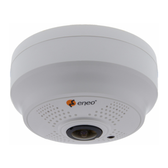
Komponenten Das System wird mit den folgenden Komponenten geliefert: • Dome-Kamera • Installationsanleitung/CD • Bohrschablone • Montageset HINWEIS: Adapter für 12V DC ist nicht im Lieferumfang enthalten.
Installation Installation Zum Betrieb der Netzwerkkamera müssen ein Netzwerkkabel zur Datenübertragung und die Stromversorgung durch das mitgelieferte Netzteil angeschlossen werden. Je nach Betriebsmethode kann ein zusätzliches Alarmkabel angeschlossen werden. Die Dome-Kamera sollte an einem Bauelement wie etwa Hartholz, einem Wandständer oder Deckenbalken befestigt werden, welches das Gewicht der Kamera trägt.
Seite 18
3. Befestigen Sie die Kamera an der Decke mit den mitgelieferten Dübeln (3x) und Schrauben (3x). Bohrschablone Schraube Dome-Kamera Kamera-Abdeckung Kunststoffdübel 4. Bringen Sie die Kamera-Abdeckung an der Dome-Kamera an. Drehen Sie die Kamera-Abdeckung im Uhrzeigersinn, um die Montage abzuschließen. Diese Öffnung ist eine Referenzpositi- on zum Zusammenbauen von Kamera- Abdeckung und Kamera-Basis.
Audio anschließen Schließen Sie Lautsprecher an den Audio-Ausgang und externe Mikrofone an den Audio- Eingang an. Anschließen von Alarmen AI (Alarmeingang) Sie können externe Geräte anschließen, die der Dome-Kamera externe Ereignisse sig- nalisieren, damit sie auf diese reagiert. Mechanische oder elektrische Schalter können zwischen die Anschlüsse AI (Alarmeingang) und G (Masse) geschaltet werden.
Legen Sie die MicroSD-Speicherkarte in den SD-Kartensteckplatz ein. Netzwerkverbindung und IP-Zuweisung Mit dem eneo Site Manager können alle eneo Netzwerk Kameras im lokalen Netzwerk erkannt werden (laden Sie die Software von www.eneo-security.com herunter). Das Tool muss nicht mit einem Setup Programm installiert werden. Die exe-Datei des Programms kann mit einem Doppelklick direkt gestartet und benutzt werden.
IP-Einstellungen zu erhalten. Wenn Sie fertig sind, klicken Sie den "OK" Button um die Kameraeinstellungen zu aktualisieren. Weitere Informationen finden Sie im eneo Site Manager Quick Start Guide. Rücksetzen auf die Werkseinstellungen Um die Netzwerkkamera auf die Werkseinstellungen zurückzusetzen, rufen Sie die Web- seite Konfiguration >...
Die aktuellsten Firmware-Versionen finden Sie auf unserer Website unter www.eneo-security.com. Das Benutzerhandbuch und weitere Software-Tools sind auf der eneo Website unter www.eneo-security.com oder auf der mitgelieferten CD verfügbar. Informationen zu kompatiblen Video Management Software-Lösungen finden Sie in der Kategorie Videomanagement unter www.eneo-security.com.
Seite 24
Contenu Composants .........................27 Installation ........................28 Installation ..................................28 Installation et réglage de la caméra ........................28 Câble d’extension ................................29 Raccordements ................................30 Connexion au port réseau............................30 Connexion audio ..............................30 Connexion des alarmes ............................30 Connexion de l´alimentation ..........................31 Insertion de la carte microSD ..........................
Instructions de sécurité Consignes de sécurité générales • Avant de brancher et de mettre en service le système, veuillez lire d'abord ces consignes de sécurité ainsi que la notice d'instructions. • Conservez soigneusement la notice d'instructions en vue d'une utilisation ultérieure. •...
• Une distance de sécurité > 1 m doit être respectée par rapport au projecteur dans un environnement sombre, quand on regarde directement dans le projecteur IR. • Les rayons invisibles des LED ne doivent pas être observés directement avec des instruments optiques (par ex.
Composants Le système est fourni avec les composants suivants : • Caméra dôme • Guide d'installation / CD • Gabarit de montage • Kit d'accessoires REMARQUE : L'adaptateur CC12V n'est pas fourni.
Installation Installation Pour utiliser la caméra réseau, il est nécessaire de brancher un câble réseau pour la trans- mission de données ainsi que la prise de courant sur le bloc d'alimentation secteur fourni. En fonction des méthodes de fonctionnement, il est également possible de connecter un câble d’alarme.
3. Fixez l'ensemble de la caméra au plafond à l'aide des chevilles (3x) et vis(3x). Gabarit de montage Caméra dôme Cache de la caméra Chevilles en plastique 4. Montez le cache de la caméra sur la caméra dôme. Tournez le cache de la caméra dans le sens des aiguilles d'une montre pour terminer l'installation.
N° Connecteur Description RJ-45 Ethernet, RJ-45 port compatible avec une alimentation 10/100Mbps ayant une fonction PoE. Connecteur Jack Alimentation principale, connecteur jack CC, 12 VCC Al : Alarm In (entrée alarme) G : GND (terre) Entrée/sortie d´alarme, terminal 3 broches AO : Alarm Out (sortie alarme) MIC : Audio In (entrée Audio) Entrée de niveau de ligne audio, terminal 2 broches...
Connexion au réseau et attribution d’une adresse IP Le gestionnaire de site eneo (téléchargeable à partir de www.eneo-security.com) est utilisé pour localiser toutes les caméras réseau eneo dans un réseau local. Un programme d´installation n´est pas nécessaire pour installer cet outil. Pour utiliser le programme, il...
Seite 32
IP de la caméra. Ensuite, cliquez sur « OK » pour mettre à jour les réglages de la caméra. Pour plus d'informations, merci de vous référer au guide de démarrage rapide du gestion- naire de site eneo (eneo Site Manager Quick Start Guide).
Assurez-vous de toujours être à jour grâce à la dernière version du progiciel disponible depuis le site d'eneo sous www.eneo-security.com pour recevoir les dernières fonction- nalités de votre produit. Le manuel utilisateur et d’autres outils logiciels sont disponibles sur le site web eneo www.eneo-security.com ou sur le CD joint.
Seite 34
Le logiciel inclus dans ce produit est protégé par des droits d'auteur et fait l'objet de licences Open source. Vous pouvez obtenir le code source complet correspondant auprès d'eneo pour une période de 3 ans à compter de la dernière livraison de ce produit par courriel à : open- source@eneo-security.com.
Seite 35
Indice Componenti .........................38 Installazione .........................39 Installazione ..................................39 Installazione e regolazione della telecamera ....................39 Cavo di prolunga ................................40 Collegamenti ................................... 41 Collegamento alla rete ............................41 Collegamento dell'audio ............................41 Collegamento degli allarmi ..........................41 Collegamento dell'alimentazione ........................42 Inserimento della scheda di memoria Micro SD ...................
Istruzioni per la sicurezza Istruzioni generali per la sicurezza • Prima di collegare e mettere in funzione il sistema, leggete le istruzioni per la sicurezza e le istruzioni per l'uso. • Conservate con cura le istruzioni per l'uso per un eventuale utilizzo futuro. •...
Seite 37
• Deve essere mantenuto un margine di sicurezza di > 1 m dal proiettore se si guarda direttamente nel proiettore IR in un ambiente buio. • Non guardare direttamente le radiazioni LED invisibili utilizzando strumenti ottici (ad es. lente, lente di ingrandimento o microscopio) per prevenire danni agli occhi ( LED classe 1M).
Componenti Il sistema viene fornito con i componenti seguenti: • Telecamera dome • Guida/CD di installazione • Dima • Kit di accessori AVVISO: l'adattatore per 12 VCC non è fornito.
Installazione Installazione Per l'utilizzo della telecamera di rete è necessario collegare un cavo di rete per la trasmis- sione dei dati e collegare l'alimentazione dall'adattatore di corrente fornito. A seconda del metodo d'uso, è possibile collegare anche un cavo di allarme. La telecamera dome deve essere fissata a un elemento strutturale, ad esempio un pezzo di legno duro, un montante o un travetto del soffitto che sostenga il peso della telecame- ra dome.
Dima Vite Telecamera dome Coperchio della telecamera Tassello di plastica 4. Montare il coperchio sulla telecamera dome. Ruotare il coperchio della telecamera in senso orario per completare l'installazione. Il foro è una posizione di riferimento per montare la parte inferiore e l'alloggiamento. Cavo di prolunga...
Connettore Descrizione RJ-45 Ethernet, porta RJ-45 compatibile con 10/100 Mbps con funzionalità PoE. Jack CC Alimentazione principale, jack CC, 12 VCC AI: ingresso allarme G: terra Ingresso e uscita allarme, terminale a 3 pin AO: uscita allarme MIC: ingresso audio Ingresso linea audio, terminale a 2 pin G: terra SPK: uscita audio...
Lo strumento eneo Site Manager (scaricabile da www.eneo-security.com) viene utilizzato per individuare tutte le telecamere di rete eneo in una rete locale. Non occorre installare lo strumento con un programma di installazione. È possibile avviare il file .exe del pro-...
Seite 43
Selezionare l'opzione "Set IP Address [dhcp / static]" (Imposta indirizzo IP [dhcp / statico]) per aprire una finestra in cui impostare le proprietà IP della telecamera. Al termine fare clic sul pulsante "OK" per aggiornare le impostazioni della telecamera. Per ulteriori informazioni consultare la guida rapida di eneo Site Manager.
Verificare sempre di aver eseguito l'upgrade all'ultima versione del firmware disponibile sul sito web eneo all'indirizzo www.eneo-security.com per disporre delle ultime funzioni del prodotto. Il Manuale utente e altri strumenti software sono disponibili sul sito web eneo all'indirizzo www.eneo-security.com oppure sul CD fornito.
Seite 45
Il software fornito con questo prodotto contiene software protetto da copyright il cui utilizzo viene concesso con licenze open source. È possibile richiedere a Eneo il codice sorgente completo per un periodo di tre anni dopo l'ultima spedizione di questo prodotto inviando un'e-mail a: opensource@eneo-security.
Seite 48
VIDEOR E. Hartig GmbH Exclusive distribution through specialised trade channels only. VIDEOR E. Hartig GmbH Carl-Zeiss-Straße 8 63322 Rödermark/Germany Tel. +49 (0) 6074 / 888-0 Technical changes reserved Fax +49 (0) 6074 / 888-100 www.videor.com...