Werbung
Verfügbare Sprachen
Verfügbare Sprachen
Quicklinks
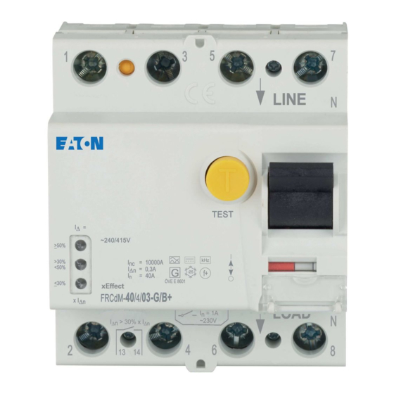
FRCdM-Type B, Bfq, B+
IMPORTANT / WICHTIG
R ins (MΩ) U test (kV)
WARNING:
Disconnect load side of
the switchgear, during
any insulation test of the
installation!
WARNUNG:
Bei lastseitiger
Isolationsprüfung der
Anlage ist das
Schaltgerät lastseitig
abzuklemmen!
<
30% I
30-50% I
DN
TEST
1
TEST
TEST
1
TEST
RESET
I D > I Dn
Dn
RESET
I D > I Dn
blue
blau
Connection/Anschluss:
N/7
Line
N/8
ON
2
1
Eaton Industries (Austria) GmbH, Eugenia 1, 3943 Schrems, Austria
© 2019 by Eaton Industries (Austria) GmbH, www.eaton.eu/documentation
Instruction Leaflet
Montageanweisung
Notice d'installation
Instrucciones de montaje
Istruzioni per il montaggio
Инструкция по монтажу
Montagehandleiding
Line
L1 L2 L3
N
o
90
o
90
L1 L2 L3
N
Load
D
> 50% I
I
>
DN
DN
grün
verde
green
zielony
vert
grön
zelený
vihreä
OFF
grøn
yeşil
verde
verde
zöld
зелена
verde
πράσινος
grønn
أﺧﻀﺮ
groen
1
OFF
white
1
weiß
OFF
1
2
N/7
Line
N/8
Montagevejledning
Οδηγίες εγκατάστασης
Instruções de montagem
Monteringsanvisning
Asennusohje
Návod k montáži
Paigaldusjuhend
Szerelési utasítás
o
90
o
90
TEST
DN
1
I
/RESET
TEST
20
17
, 201 , 201
8
9
RESET
I D > I Dn
ON
1, 2, 3, 4, 5, 6, N, N:
ON
2
2 2,4Nm
-
ON
2
The potential free auxiliary contact
(13,14) provides only basic insulation
N/7
Isolation trans-
Line
former 1:1
from load side terminals (2/4/6/N) of the
RCCB. Without any additionall protectiv
measures (Isolation transformer 1:1
according to IEC/EN60664) the potential
free auxiliary contact (13,14) may only
be supplied from the load side terminals
(2/4/6/N). See application according
N/8
www.eaton.com/recycling
Montāžas instrukcija
Montavimo instrukcija
Instrukcja montażu
Navodila za montažo
Návod na montáž
Монтажни инструкции
Instrucţiuni de montaj
Upute za montažu
5mm
Z2
Z2
2
5mm
0,8 - 2mm
1
1
12mm
2
CLICK
2
3
CLICK
ot
r
vermelho
red
13, 14:
czerwony
rouge
röd
červený
punainen
1
rød
kı
rm z
ı ı
OFF
rojo
roșu
vörös
црвена
rosso
κόκκινος
rød
(1x2 Klemmen/Terminals)
أﺣﻤﭼﺮ
rood
Maximum back-up fuse
Max. zulässige Vorsicherung
1,5 - 35mm² Cu only
2,5 - 35mm²
Flexible Cu cable
without ferrule
Der potentialfreie Hilfskontakt (13,14)
ist zu den lastseitigen Klemmen
(2/4/6/N) des FI-Schalters basisisoliert
Steuertrafo 1:1 gemäß IEC/EN60664)
nur von den lastseitigen Klemmen
(2/4/6/N) versorgt werden. Beschaltung
figure 1, 2.
MA-dRCB-B.qxd / 10.2019k / IL019013ZU / 180503203
Kullanma Talimatı
Инструкција за монтажу
Intruksjonsblad
Монтажна інструкція
تª ø¥u¤ة اL[ 
Z2
3
2
2-2,4Nm
1
2
/ 1,5 - 35mm²
4
I = 0,25A (ohmic, ohmsch)
N
240V~
ON
2
optional
/ 0,25 - 1,5mm²
I n = 16-63A
63 A gG/gL
I n = 16-63A
63 A gG/gL
und darf daher ohne weitere
Maßnahmen (sicher getrennter
siehe Bild 1, 2.
All Rights Reserved / Printed in Austria
Werbung

Inhaltszusammenfassung für Eaton FRCdM
- Seite 1 (2/4/6/N) versorgt werden. Beschaltung (2/4/6/N). See application according siehe Bild 1, 2. figure 1, 2. Eaton Industries (Austria) GmbH, Eugenia 1, 3943 Schrems, Austria MA-dRCB-B.qxd / 10.2019k / IL019013ZU / 180503203 www.eaton.com/recycling © 2019 by Eaton Industries (Austria) GmbH, www.eaton.eu/documentation...
- Seite 2 Disconnect load side of the switchgear, if you make a insulation test of the installation! Bei lastseitiger Isolationsprüfung der Anlage ist das Schaltgerät lastseitig abzuklemmen! Eaton Industries (Austria) GmbH, Eugenia 1, 3943 Schrems, Austria MA-dRCB-B.qxd / 10.2019k / IL019013ZU / 180503203 www.eaton.com/recycling...


