Inhaltsverzeichnis

Verwandte Anleitungen für HYDAC International FSA Serie

Inhaltszusammenfassung für HYDAC International FSA Serie
- Seite 1 Bedienungsanleitung Operating Manual Manuel d’utilisation Flüssigkeits- standanzeige FSA mit Rückschlagventilen Fluid Level Gauges FSA with Check Valves Contrôleurs de niveau FSA avec clapets anti-retour...
-
Seite 3: Funktion Rückschlagventil
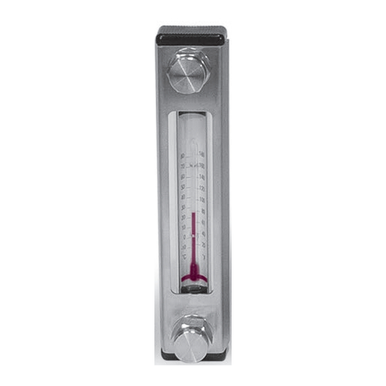
Allgemein Zum ordnungsgemäßen Einsatz dieser Flüssigkeitsstandsanzeigen FSA mit Rückschlagventilen ist die folgende Betriebsanleitung zwingend zu beachten. Funktion 2.1. FUNKTION RÜCKSCHLAGVENTIL Die Verwendung der Rückschlagventile ist nur in Verbindung mit HYDAC Flüssigkeitsstandanzeigen zulässig. Das Rückschlagventil ist ein federbelastetes Kegelsitzventil, das unbetätigt geschlossen ist. - Seite 4 Durch gleichzeitiges Drücken des oberen und unteren Knopfes der Rückschlagventile bis zum Anschlag wird der aktuelle Füllstand in dem Anzeigerohr der Füllstandsanzeige angezeigt. Bei optionaler Verwendung eines Thermometers wird zusätzlich die aktuelle Flüssigkeitstemperatur angezeigt. Rückschlagventil in Ausgangsstellung geschlossen Rückschlagventil betätigt Drücken offen Zur Flüssigkeitsniveau-...
- Seite 5 2.2. FUNKTION FSA HYDAC Flüssigkeitsstandanzeigen überwachen das Füllstandsniveau in einem Hydraulikbehälter. Die Unterschreitung eines Minimalniveaus oder die Überschreitung eines Maximalniveaus wird dabei über die optische Anzeige des Füllstandes und über Minimal- oder Maximalmarkierungen auf der Kontrastscheibe oder eine Hohlkugel übermittelt. Der jeweilige Füllstand des Behälters lässt sich im Schauglas optisch ablesen.
-
Seite 6: Benennung & Symbol
Kenngrößen FSA mit Rückschlagventil 3.1. BENENNUNG & SYMBOL 3.2. BAUART Das Rückschlagventil ist in nur Verbindung mit der Flüssigkeitsstandsanzeige zum direkten Anbau an einen Druckflüssigkeitsbehälter konzipiert. 3.3. BEFESTIGUNGSART Behälterseitig Gewindebohrung M12 3.4. EINBAULAGE Senkrecht an der Behälterwand 3.5. MASSE FSA 076 + 2 IB – 0,29 kg FSA 127 + 2 IB –... -
Seite 7: Hydraulische Kenngrössen
3.6. UMGEBUNGS- TEMPERATURBEREICH min. 0 ºC max. +100 ºC 3.7.1 Werkstoffe – Rückschlagventil Ventilkörper, Kegel, Druckknopf, Feder: Edelstahl Dichtungen: Viton (FKM) oder Perbunan (NBR) 3.7.2 Werkstoffe – FSA Anschlussstücke: hochwertiger Kunststoff oder Aluminium Steigrohr: Glasrohr (rund) Gehäuserahmen: Edelstahl Dichtungen: Viton (FKM) oder Perbunan (NBR) 3.8. - Seite 8 Betriebsbedingungen 4.1. ALLGEMEIN z Überschreitung des angegebenen Betriebsdruckes bzw. Über- und Achtung Unterschreitung der Betriebstemperatur führt zur Undichtheit und Zerstörung der Flüssigkeitsanzeige. z Flüssigkeitsanzeigen sind nur für angegebene Medien zu benutzen. z Bei Einsatz im Hochtemperaturbereich sind bei Betätigung geeignete Schutzhandschuhe erforderlich.
-
Seite 9: Geräteabmessungen
4.2. GERÄTEABMESSUNGEN FSA 076 - 381 - IB Hub 2.2 Farbe: Anzugs- schwarz drehmoment 8-10 Nm Nenngröße Rahmen mit Stegbreite 9 mm Anzugs- drehmoment 8-10 Nm Farbe: Nenngröße L1 L3 Anzahl Sichtfenster FSA-076 76 108 FSA-127 88 127 159 FSA-176 137 176 208 FSA-254 215 254 286... - Seite 10 FSA 500 - 1000 - IB Hub 2.2 Anzugs- drehmoment 8-10 Nm Anzugs- drehmoment 8-10 Nm Nenngröße L1 F Anz. FSA-500 535 137 FSA-600 635 170 FSA-700 735 150 FSA-800 835 175 FSA-900 935 158 FSA-1000 932 1000 1035 147...
- Seite 11 4.3. TYPISIERUNG FSA - 254 - 2 . 0 / T / 12 - S07 / S078 2xIB ... Füllstandsanzeige Baugröße 1000 Abdichtung 1 = Perbunan 2 = Viton Glasrohr (rund) Ab Baugröße 500 mit Hohlkugel Thermometer (im Glasrohr) Nur bis Baugröße 381 Gewinde der Hohlschraube Rahmen, Schrauben und Muttern aus Edelstahl...
- Seite 13 General The following instructions must be strictly followed to ensure correct use of this FSA fluid level gauge with check valves. Function 2.1. FUNCTION OF THE CHECK VALVE The use of the check valves is only permitted in conjunction with HYDAC Fluid Level Gauges.
- Seite 14 By pressing fully on the buttons of both top and bottom check valves simultaneously, the actual fluid level will be indicated in the sight tube of the level gauge. If the temperature gauge option is being used, the actual fluid temperature is also displayed.
- Seite 15 2.2. FUNCTION OF FSA HYDAC fluid level gauges monitor the fluid level in a hydraulic tank. If the level falls below a minimum, or exceeds a maximum, this is indicated via the visual display of the fluid level, via the minimum and maximum marks on the label or via a hollow ball.
-
Seite 16: Mounting Position
3. Technical specifications for FSA with check valve 3.1. DESIGNATION & SYMBOL 3.2. TYPE OF CONSTRUCTION The check valve is designed to be used only in conjunction with the fluid level gauge for direct mounting onto a hydraulic tank. 3.3. TYPE OF MOUNTING Threaded holes on the tank side M12 3.4. -
Seite 17: Hydraulic Specifications
3.6. AMBIENT TEMPERATURE RANGE min. 0 ºC max. +100 ºC 3.7.1 Materials of Check Valve Valve housing, cone, push-button, spring: stainless steel Seals: Viton (FKM) or Perbunan (NBR) 3.7.2 Materials of FSA End caps: high quality synthetic material or aluminium Sight tube: glass tubing (round) Housing:... - Seite 18 Operating conditions 4.1. GENERAL z If the specified operating pressure is exceeded, or the operating temperature Warning is exceeded or falls too low, the result can be leakage and irreparable damage to the fluid level gauge. z Fluid level gauges must only be used for the specified fluids.
- Seite 19 4.2. DIMENSIONS FSA 076 - 381 - IB Hub 2.2 Colour: Torque value black 8-10 Nm Size 381 Housing with strengthening Width 9 mm Torque value Colour: 8-10 Nm Nominal L3 Number size of viewing windows FSA-076 76 108 FSA-127 88 127 159 FSA-176 137 176 208...
- Seite 20 FSA 500 - 1000 - IB Hub 2.2 Torque value 8-10 Nm Torque value 8-10 Nm Nominal F No. size of F FSA-500 535 137 FSA-600 635 170 FSA-700 735 150 FSA-800 835 175 FSA-900 935 158 FSA-1000 932 1000 1035 147...
-
Seite 21: Model Code
4.3. MODEL CODE FSA - 254 - 2 . 0 / T / 12 - S07 / S078 2xIB ... Type Fluid level gauge Size 1000 Seals 1 = Perbunan 2 = Viton Glass tube (round) Sizes 500 and above have a hollow ball Thermometer (in the glass tube) - Seite 23 Généralités Pour une utilisation conforme de ces contrôleurs de niveau FSA avec clapets anti-retour, il est nécessaire de respecter expressément cette notice d‘utilisation. Fonction 2.1. FONCTION CLAPET ANTI-RETOUR L‘utilisation des clapets anti-retour n‘est conseillée que pour le raccordement avec les indicateurs de niveau HYDAC. Le clapet anti-retour est une valve sur siège à...
- Seite 24 Par une pression simultanée des boutons supérieur et inférieur jusqu‘en butée des clapets anti-retour, le niveau de remplissage actuel s‘affiche dans le tube de visualisation de l‘indicateur de niveau. En utilisant en option un thermomètre, la température instantanée du fluide pourra être visualisée.
- Seite 25 2.2. FONCTION DU FSA Les indicateurs de niveau HYDAC surveillent le niveau du fluide dans un réservoir hydraulique. Le passage à un niveau minimal ou maximal est indiqué via l‘indicateur de niveau visuel et les marquages mini et maxi sur le disque de contraste ou d‘une bitte creuse.
-
Seite 26: Sens De Montage
Données techniques du FSA avec clapet anti-retour 3.1. DESIGNATION & SYMBOLE 3.2. CONSTRUCTION Le clapet anti-retour n‘est conçu qu‘en liaison avec un indicateur de niveau de fluide pour montage direct sur un réservoir. 3.3. MODE DE FIXATION Taraudage M12 côté réservoir 3.4. - Seite 27 3.6. PLAGE DE TEMPERATURE AMBIANTE min. 0 ºC màx. +100 ºC 3.7.1 Matériaux – clapet anti-retour Corps de valve, clapet, bouton poussoir, ressort: inox Joints: Viton (FKM) ou Perbunan (NBR) 3.7.2 Matériaux – FSA Pièces de raccordement: matière synthétique hautes caractéristiques ou aluminium Tube: tube de verre (rond) / Pyrex...
- Seite 28 Conditions de fonctionnement 4.1. GENERALITES z Une température en dehors de la plage préconisée peut provoquer des fuites Attention et des détériorations au niveau de l‘indicateur. z Les indicateurs de niveau ne doivent être utilisés que pour les fluides indiqués. z En cas d‘utilisation à...
- Seite 29 4.2. DIMENSIONS FSA 076 - 381 - IB Hub 2.2 couleur : couple de noir serrage 8-10 Nm Taille nominale cadre avec passerelle Largeur 9 mm couple de serrage couleur : 8-10 Nm rouge Taille L3 Nombre de nominale fenêtres de visualisation FSA-076 76 108...
- Seite 30 FSA 500 - 1000 - IB Hub 2.2 couple de serrage 8-10 Nm couple de serrage 8-10 Nm Taille F No. nominale de F FSA-500 535 137 FSA-600 635 170 FSA-700 735 150 FSA-800 835 175 FSA-900 935 158 FSA-1000 932 1000 1035 147...
- Seite 31 4.3. CODIFICATION FSA - 254 - 2 . 0 / T / 12 - S07 / S078 2xIB ... Type Indicateur de niveau Taille nominale 1000 Matériau des joints 1 = Perbunan 2 = Viton Tube Verre (rond) De taille 50 avec bille creuse Thermomètre (dans le tube)
- Seite 32 HYDAC Hirschbachstr. 2 ACESSORIES GmbH D-66280 Sulzbach Phone: +49 (0) 6897 / 509-1001 Fax: +49 (0)6897 / 509-1009 Internet: www.hydac.com...