AVS Electronics JET DT WS 4 Anleitung
Quicklinks
IT ALIANO
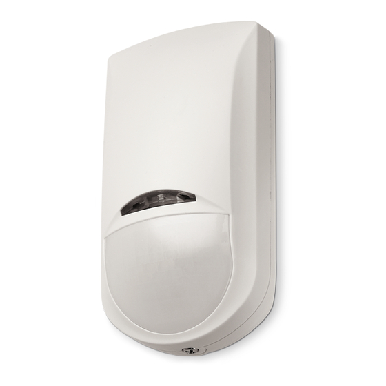
CARATTERISTICHE GENERALI
Jet DT WS 4 è un sensore volumetrico da interno a doppia tecnologia gestito da microprocessore, nel quale l'abbinamento tra un infrarosso passivo
a lente di Fresnel ed una microonda planare, crea una protezione molto efficace contro i falsi allarmi in ambienti critici.
CARATTERISTICHE TECNICHE
Tensione nominale
3,6 V =
Batteria al litio tipo
SIZE AA - 2,2Ah
Assorbimento
18 μA in quiete - 42 mA in allarme
Frequenza microonda
Paesi della Comunità Europea eccetto Germania: 10,525 GHz
Germania: 9,350 GHz
Tipo trasmissione
bidirezionale
Numero canali radio
10
Rolling Code
si
Cambio automatico canale radio
si
Regolazione automatica potenza radio in
si
trasmissione
Larghezza di banda per canale
25 KHz
Frequenza di trasmissione (FM - 868 MHz)
Vedi Tabella G
Portata in campo aperto
~ 200 m
Copertura
90° su 15mt max
Segnalaz. batteria bassa
si
Segnalaz. sopravvivenza
si
Condizioni ambientali
0° C +50° C
Umidità
95%
Peso
120 gr
Dimensioni (millimetri) (PxLxH)
39 x 65 x 120
Installazione
sensore da interno
Pet Immunity (No lente opzionale CLI)
Immunità ad animali di piccola taglia (non regolabile)
PROGRAMMAZIONE E INDIRIZZAMENTO
Tutta la programmazione del sensore, compreso l'indirizzamento, avviene esclusivamente tramite la centrale.
Questi sensori ricevono dati via radio dalla centrale o dal ricevitore soltanto subito dopo aver effettuato una trasmissione.
Di conseguenza, quando si fanno modifiche alla programmazione di un sensore nella centrale, per renderle effettive è necessario far sì che il sensore
in questione trasmetta almeno una volta, per acquisire i nuovi parametri impostati.
NOTA: dato che la centrale controlla continuamente che la programmazione di ogni sensore corrisponda a ciò che è stato impostato, prima si
possono fare in centrale le programmazioni di tutti i sensori che si desidera configurare e poi, con calma, una volta usciti da programmazione, si fa
attivare un sensore alla volta per fargli acquisire la nuova configurazione, oppure si può lasciare che la acquisisca da solo alla prima trasmissione di
supervisione ogni 15 minuti. Si consiglia comunque di controllare che ogni sensore si comporti come ci si aspetta in base alla configurazione fatta.
-
ANTIMASK: formato da tre trasmettitori ed un ricevitore ad infrarossi posizionato attorno al PIR che rilevano gli ostacoli (nastro adesivo, quasi
tutte le vernici) posti di fronte al sensore fino ad una distanza di circa 5 cm. FUNZIONAMENTO: quando il sensore rileva un ostacolo a meno
di 5 cm, attiva una temporizzazione di circa un minuto;se alla fine di questo tempo l'ostacolo non viene rimosso, comunica il mascheramento.
La segnalazione viene resettata automaticamente al primo allarme del sensore.
-
ACCELEROMETRO: per la segnalazione dello strappo e disorientamento (non rileva la vibrazione). Una eventuale rimozione non autorizzata
viene segnalata dal sensore come TAMPER
-
CONSUMO RIDOTTO: in seguito ad una trasmissione di allarme, il sensore continua ad analizzare l'ambiente da proteggere ma non esegue
un'ulteriore trasmissione se non dopo un periodo di circa 3 minuti in cui non rileva nulla.
-
RV1: Trimmer per la regolazione portata microonda. Aumenta in senso orario
COPERTURA
-
Con lente in dotazione (Fig. A): apertura 90°, portata di 15 metri con altezza di installazione a 2,2 metri da terra
-
Con lente opzionale (Mod. CLI) (Fig. B): apertura 5°, portata di 15 metri con altezza di installazione a 2,2 metri da terra.
CAMBIO LENTE MOD. CLI (OPZIONALE) (FIG. E) (NO PET IMMUNITY)
Dall'interno del coperchio, sganciare i due fermi (12) posti ai lati della lente installata (13), inserire il convogliatore (14) e poi la lente mod. CLI
INSTALLAZIONE DEGLI SNODI MOD. K21 E MOD. K21T (OPZIONALI) (FIG. F)
-
A parete: assemblare e fissare, con la vite (8) e il dado (2), i pezzi (1, 9, 6) che compongono lo snodo, al fondo del sensore (7).
-
A soffitto: assemblare e fissare, con la vite (8) e il dado (2), i pezzi (1, 4, 6) che compongono lo snodo, al fondo del sensore (7).
Per entrambi gli snodi, posizionare il modulo Antistrappo (3)
MESSA IN FUNZIONE
-
Per la messa in funzione dei dispositivi della serie bidirezionale tenere presente le seguenti informazioni:
-
Il led lampeggia ogni volta che il sensore trasmette.
-
Se il sensore è già stato acquisito da un ricevitore e la copertura radio è buona, ad ogni allarme il lampeggia brevemente una volta soltanto e poi
si spegne, segno che ha ricevuto la conferma di ricezione da parte del ricevitore.
-
Osservare il numero di ripetizioni che il sensore fa dopo ogni allarme per valutare la bontà della copertura radio del posto prescelto.
-
Se il sensore nel trasmettere gli allarmi è costretto spesso a ripetere più volte (più lampeggi consecutivi del led) è indice che si trova al limite della
portata radio e conviene spostarlo in posizione più favorevole.
-
Se il sensore non è ancora stato acquisito, ad ogni allarme trasmetterà sempre 6 ripetizioni.
-
Si consiglia di acquisire sempre i sensori sul ricevitore prima di effettuare le prove di funzionamento per evitare confusione con le segnalazioni del led.
ACQUISIZIONE
L'acquisizione dei sensori avviene solo effettuando una trasmissione di tamper; ogni sensore andrà ad occupare in centrale una posizione di zona
distinta in ordine crescente a partire dalla prima libera disponibile.
CANCELLAZIONE CODICE CENTRALE
Se si vuole svincolare il sensore dalla centrale per poterlo riutilizzare in un altro impianto, è necessario eseguire la seguente procedura
per cancellare il codice centrale memorizzato:
•
togliere e reinserire la batteria del sensore
•
nei primi 10 secondi premere 3 volte in rapida sequenza il pulsante del TAMPER
•
se l'operazione viene accettata, il led verde si accenderà di luce fissa per qualche secondo
La dichiarazione di conformità può essere consultata nell'area riservata del sito AVS Electronics.com
INSTALLAZIONE E MANUTENZIONE DEVONO ESSERE FATTE DA PERSONALE QUALIFICATO
Il prodotto è conforme alla direttiva CE per la compatibilità elettromagnetica.
AVS ELECTRONICS S.p.a. si riserva il diritto di apportare modifiche in qualsiasi momento e senza preavviso.
Curtarolo (Padova) Italy
www.avselectronics.com
JET DT WS 4
90°
96°
5°
PIR
MW
A
B
C
2,2m
22.0000
1m 2m 3m 4m
5m 6m 7m 8m 9m 10m 11m 12m 13m 14m 15m
F
10
9
1
2 3
10
1
1
10
2
2
11
9
3
10
6
4
6
5
5
7
8
G
Bande di frequenza usate
Massima
Numero di
Occupied frequency bands
potenza
irradiata
Band number
(ETSI EN 300 220-3-2 V1.1.1
Maximum
(2017-02)
According to
radiated
Wireless alarm equipment)
EC Decision
power
2013/752/EU [i.2]
A
868,600 MHz to 868,700 MHz
<10 mW e.r.p.
D
869,300 MHz to 869,400 MHz
<10 mW e.r.p.
E
869,650 MHz to 869,700 MHz
<10 mW e.r.p.
FEATURES
Jet DT WS 4 is a microprocessor volumetric indoor dual-technology detector. The combination between a mirror passive infrared
and a planar microwave creates a highly efficient protection against false alarms in critical situations.
GENERAL CHARACTERISTICS
Nominal tension
Lithium battery
Consumption
Microwave frequency
Transmission
Radio channel number
BATT.
Rolling Code
D
Automatic channel changing
Automatic transmission power adapting
Channel band width
Transmission frequency (FM - 868 MHz)
Range in open air
Coverage
Low-battery indication
"Life" indication
Working temperature
Humidity
LED
Weight
Size (mm) (PxLxH)
Installation
Pet Immunity (No optional CLI lens)
TAMPER
PROGRAMMING AND PAIRING
Detector is fully programmable only through its own wireless panel (also the pairing code).
This detector receives wireless data from its own wireless panel (or from its receiver) only after one detector transmission.
So, when you make a detector programming changing on the control panel, it's necessary that the detector makes a transmission
to activate the changings on the detector itself.
NOTE: due to the fact that the control panel check constantely the correspondence of each detector programming status with the original
E
set up, the installer can make on the control panel the complete programming of all detectors installed, then activating one by one each
detector the programming will be transmitted to the detector; otherwise can wait the first detector supervision transmission (each 15
minutes). In any case, after any programming changing, it is necesary to check that each detector is runneing the right programming.
-
ANTIMASK: three transmitters and one infrared receiver around the PIR detector check the obstacles (adhesive tape, must of
14
painting) place in front of the detector up a distance of 5 cm. FUNCTIONING: when the detector detects an obstacle at less then
5 cm, is starting a timing of about 1 minute; if, at the end of the timingthe obstacle is still permanent, it'll perform a MASKING
alarm. The alarm will be resetted at the next alarm condition.
-
ACCELEROMETER: for the reporting tear and disorientation (does not detect vibration). Any unauthorized removal is signalled
12
by the sensor as a TAMPER.
13
-
LOW CONSUMTION: After an alarm transmission, the detector continues to analyze the surrounding space but won't emit any
more, at least for the following 3 min during which it detects nothing.
-
RV1: Trimmer for adjusting microwave capacity, increases when turned clockwise
COVERAGE
-
With the lens provided: opening span 90°, capacity for 15 metres with height of installation at 2.2 metres above the ground.
-
With the optional lens (Mod. CLI): opening span 5°, capacity for 15 metres with height of installation at 2.2 metres above the ground.
REPLACING THE MOD. CLI OPTIONAL LENS (FIG. E) (NO PET IMMUNITY)
Release the two clips (12) either side of the lens (13) from inside the cover, apply the window narrower (14) and the curtain lens
mod. CLI
INSTALLATION OF THE MOD. K21 AND MOD. K21T SUPPORT (OPTIONALS) (FIG. F)
7
8
-
Wall-mounted: use the screw (8) and nut (2) to secure the parts (1, 9, 6) of the support to the base of the sensor (7).
-
Ceiling-mounted: use the screw (8) and nut (2) to secure the parts (1, 4, 6) of the support to the base of the sensor (7).
-
In the case of both the supports, install the anti-tamper module (3)
START UP
-
Startup of bidirectional devices please consider the following:
-
LED flash each time the detector is in transmission
-
When the detector has been already paired to his receiver and the radio signal level is good, LED is flash just one time, that
mean that the receiver sent the transmission of aknowledge to the detector.
-
Quality of radio signal (and also good detector position) can easely checked by the flashing number after each alarm transmission.
-
When the detector, during alarm transmission, is flashing several times means that the radio signal is close to the limit, so that
it is suggested to change the detector position.
-
Numero di
When detector is not yet paired to his receiver, will flash 6 times at each alarm transmission
-
We suggest to pair the detector to the receiver before performing functional test to avoid mistakes with LED flashing codes
banda
sottoclasse
DETECTOR PAIRING
della Classe 1
Class 1 sub-
The detector pairing happen only with a TAMPER alarm transmission; each detector will be associated to the first free
class number
zone in the control panel.
CANCELLATION OF THE CODE OF THE CONTROL PANEL
(Commision
Decision 2000/299/
To detach the sensor from the control panel for reuse in another system, it is necessary to perform the following procedure to delete
EU [i.5]
the control panel code memorised:
•
remove and reinsert the sensor battery
•
49
32
in the first 10 seconds press the TAMPER button 3 times in quick succession
•
If the operation is successful, the GREEN LED light will come up steadily for a few seconds
53
72
The declaration of conformity is available for reference in the reserved area of the website AVS Electronics.com.
55
34
INSTALLATION AND MAINTENANCE MUST BE CARRIED OUT BY QUALIFIED PERSONNEL
The product is in conformity to the regulations for the electro-magnetic compatibility
IST0954V1.4
AVS ELECTRONICS S.p.a. reserves the right to revise or make changes to this product at any time and without notification.
ENGLISH
3,6 V =
SIZE AA - 2,2Ah
18 μA while quiet - 42 mA during alarm
European Community countries except Germany: 10.525 GHz
Germany: 9,350 GHz
bidirectional
10
yes
yes
yes
25 KHz
see Table G
~ 200 m
90° on max 15 mt
yes
yes
0° C +50° C
95%
120 gr
39 x 65 x 120
Indoor detector
Immunity to small animals (not adjustable)

Verwandte Anleitungen für AVS Electronics JET DT WS 4


Inhaltszusammenfassung für AVS Electronics JET DT WS 4
- Seite 1 FEATURES Jet DT WS 4 è un sensore volumetrico da interno a doppia tecnologia gestito da microprocessore, nel quale l’abbinamento tra un infrarosso passivo Jet DT WS 4 is a microprocessor volumetric indoor dual-technology detector. The combination between a mirror passive infrared a lente di Fresnel ed una microonda planare, crea una protezione molto efficace contro i falsi allarmi in ambienti critici.
- Seite 2 Jet DT WS 4 ist ein volumetrischer Sensor mit Dualtechnologie, gesteuert durch einen Mikroprozessor. Eine Kombination aus Infrarot Jet DT WS 4 son detectores volumétricos de doble tecnología controlados por microprocesador, en los cuales la combinación entre un infrarrojo Jet DT WS 4 est un capteur volumétrique à double technologie pour l’intérieur gérés par un microprocesseur, dans lesquels l’association Passiv Fresnel-Linse und planaren Mikrowellen erzeugt einen sehr wirksamen Schutz gegen Fehlalarme in kritischen Umgebungen.