Inhaltsverzeichnis
Werbung
Verfügbare Sprachen
Verfügbare Sprachen
Quicklinks
TMG Corporate Website
Disclaimer:
All trademarks appearing within this PDF are trademarks of their respective owners.
Form 080/01
Complimentary Reference Material
This PDF has been made available as a complimentary service for you to assist in
evaluating this model for your testing requirements.
TMG offers a wide range of test equipment solutions, from renting short to long
term, buying refurbished and purchasing new. Financing options, such as
Financial Rental, and Leasing are also available on application.
TMG will assist if you are unsure whether this model will suit your requirements.
Call TMG if you need to organise repair and/or calibrate your unit.
If you click on the "Click-to-Call" logo below, you can all us for FREE!
TMG Products Website
Werbung
Kapitel
Inhaltsverzeichnis

Verwandte Anleitungen für Rohde & Schwarz Hameg HM8135

Inhaltszusammenfassung für Rohde & Schwarz Hameg HM8135
- Seite 1 Complimentary Reference Material This PDF has been made available as a complimentary service for you to assist in evaluating this model for your testing requirements. TMG offers a wide range of test equipment solutions, from renting short to long term, buying refurbished and purchasing new. Financing options, such as Financial Rental, and Leasing are also available on application.
- Seite 3 3 G H z R F - S y n t h e s i z e r H M 8 1 3 5 Handbuch / Manual Deutsch / English...
-
Seite 4: Allgemeine Hinweise Zur Ce-Kennzeichnung
A l l g e m e i n e H i n w e i s e z u r C E - K e n n z e i c h n u n g Hersteller HAMEG Instruments GmbH KONFORMITÄTSERKLÄRUNG Manufacturer Industriestraße 6... -
Seite 5: Inhaltsverzeichnis
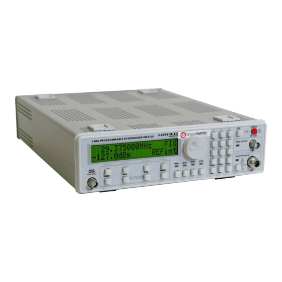
I n h a l t s v e r z e i c h n i s English PREV.-Taste ON-Taste Deutsch RCL- / STO-Tasten (Recall/Store) Allgemeine Hinweise zur CE-Kennzeichnung Fernbedienung Schnittstellen 3 GHz HF-Synthesizer HM8135 Unterstützte Befehle Bedeutung der Fehlercodes Technische Daten Flussdiagramme (Flow charts) Wichtige Hinweise... - Seite 6 H M 8 1 3 5 3 G H z H F - S y n t h e s i z e r H M 8 1 3 5 HO870 USB Schnittstelle Herausragender Frequenzbereich von 1 Hz bis 3 GHz Ausgangspegel von -135 dBm bis +13 dBm Frequenzauflösung von 1 Hz (Genauigkeit 0,5 ppm)
-
Seite 7: Ghz Hf-Synthesizer Hm8135
T e c h n i s c h e D a t e n Genauigkeit: ± 4 % des angezeigten Wertes ± 0,5 % (AM-Grad ≤ 80 % und f ≤ 50 kHz) 3 GHz HF-Synthesizer HM8135 Ext. Frequenzgang (bis - 1 dB): 10 Hz bis 100 kHz bei AC bei 23 °C nach einer Aufwärmzeit von 30 Minuten ‹... -
Seite 8: Wichtige Hinweise
W i c h t i g e H i n w e i s e Es sollte darauf geachtet werden, dass nicht mehr als drei bis Wichtige Hinweise vier Geräte übereinander gestapelt werden. Ein zu hoher Gerä- teturm kann instabil werden und auch die Wärmeentwicklung kann bei gleichzeitigem Betrieb aller Geräte, zu groß... -
Seite 9: Bestimmungsgemäßer Betrieb
W i c h t i g e H i n w e i s e 10-stündigen „Burn in-Test“. Im intermittierenden Betrieb wird Verwenden Sie keinen Alkohol, Lösungs- oder dabei fast jeder Frühausfall erkannt. Anschließend erfolgt ein Scheuermittel. Keinesfalls darf die Reinigungs- umfangreicher Funktions- und Qualitätstest, bei dem alle Be- fl... -
Seite 10: Bedienelemente Des Hm8135
B e d i e n u n g s e l e m e n t e H M 8 1 3 5 NUMERISCHE TASTATUR: Eingabeparameter mit Maß- Bedienungselemente HM8135 einheit ON: Taste zur Aktivierung des Ausgangs Geräte-Frontseite ESC (Escape): Taste zum Rücksprung ins Hauptmenü RF OUTPUT 50 Ω... -
Seite 11: Einführung In Die Bedienung Des Hm8135
D i e B e d i e n u n g d e s H M 8 1 3 5 Einführung in die Bedienung des HM8135 Die Bedienung des HM8135 Inbetriebnahme Display Beachten Sie bitte besonders bei der ersten Inbetriebnahme Die Anzeige zeigt die Frequenz und den Pegelwert des RF- des Gerätes folgende Punkte: Ausgangssignals, sowie die verwendete Referenz (INTern oder... -
Seite 12: Wahl Des Pegels
D i e B e d i e n u n g d e s H M 8 1 3 5 Ein neuer Funktionswert kann über die Tastatur , mit Die Parameterauswahl für die Funktionen AM/FM/PM erfolgt dem Drehknopf oder mit den kontextsensitiven Tasten erneut über die kontextsensitiven Tasten eingestellt werden. -
Seite 13: Modulationsarten
M o d u l a t i o n s a r t e n Beispiel 1: CH1 — > Demoduliertes Signal: DC gekoppelt CH2 — > Demoduliertes Signal: AC gekoppelt Mit der PREV.-Taste wird zum vorherigen Menüpunkt zurückgeschaltet. Mit der ESC-Taste wird zum Haupt- Display umgeschaltet. -
Seite 14: Frequenzmodulation (Fm)
M o d u l a t i o n s a r t e n Frequenzmodulation (FM) Beispiel 4: Für AM Rechteck (Modulationsgrad: 50%) erhält man: Nach Auswahl der Option DEV (FM MENU) mittels der kontext- sensitiven Tasten zeigt das Display: Ein neuer Funktionswert kann über die Tastatur , mit dem Drehgeber... -
Seite 15: Phasenmodulation (Pm)
M o d u l a t i o n s a r t e n Phasenmodulation (PM) FSK Modulation Nach Auswahl der Option DEV (PM MENU) mittels der kontext- Nach Auswahl der Optionen F0 oder F1 (FSK-MENU) mittels sensitiven Tasten zeigt das Display: der kontextsensitiven Tasten zeigt das Display:... -
Seite 16: Gate Modulation
E i n s t e l l u n g d e r G e r ä t e k o n f i g u r a t i o n Beispiel 14: (Fgate: 250 Hz Sqr) GATE Psk0: –3,14 rad;... -
Seite 17: Menu-Taste
E i n s t e l l u n g d e r G e r ä t e k o n f i g u r a t i o n MENU-Taste Achtung! Sollte der digitale Drehgeber nicht funk- tionieren, ist diese Option zu prüfen! Interface COM SWEEP... -
Seite 18: Prev.-Taste
F e r n b e d i e n u n g Nach Betätigung der STO-Taste zeigt das Display: Fstr: 16.000000 MHz – stp + Fstp: 1200.000000 MHz Die aktuelle Konfi guration wird mit einer Zahl zwischen 0-9 (numerische Tastatur) abgespeichert. –... -
Seite 19: Unterstützte Befehle
F e r n b e d i e n u n g Der Anwender kann mit dem Befehl LK1 alle Bedienungsele- Fernsteuerung aus mente sperren. Das Display zeigt dann: Fernsteuerung ein Sound Befehle Beep aus leiser Beep Unterstützte Befehle lauter Beep Allgemein Befehle OUTPUT... - Seite 20 F e r n b e d i e n u n g string folgt automatisch die Bezeichnung der Einheit Hz (z.B. Befehlszeile (1) dient Modulationsgradeinstellung. Der <NUM> 34000000 Hz für 34 MHz). Die Optionen :CW und :FIXed haben Parameter ist ein bereichsspezifi scher NR2 Daten-string (siehe auf das Instrument keine Wirkung.
- Seite 21 F e r n b e d i e n u n g Befehle PM (Phase Modulation) oder NR3 Datenstring (siehe Abschnitt Syntaxkonvention). Dem Datenstring folgt automatisch die Bezeichnung der Einheit Hz (z.B. 34000000Hz für 34 MHz). Phasenmodulation Befehlszeile (2) dient der aktuellen Frequenzhubabfrage. Das Syntax: Instrument sendet einen NR3 Datenstring ohne Einheit.
- Seite 22 F e r n b e d i e n u n g Das Instrument sendet 0 bei nicht aktivierter PM Modulation Die Befehlszeilen (3) und (5) dienen der PSK Phaseneinstellung und sendet 1 bei aktivierter PM Modulation. (PH0 bzw. PH1). Der <NUM> Parameter ist ein bereichsspe- zifi...
-
Seite 23: Befehle System
F e r n b e d i e n u n g Bedeutung des Fehlercodes Beispiel: :SWE:TIME 5; :FREQ:STAR 16E+6;:FREQ:STOP 1.2E+9; :FREQ: MODE SWE Kein Fehler Direct Digital Synthesis-Fehler (Hardware) Befehle SYSTEM Interner Referenzfehler (Hardware) Syntax: Externer Referenzfehler (Hardware) :SYSTem:ERRor? Diese Befehlszeile dient der Abfrage des aktuellen Fehlercodes. -
Seite 24: General Remarks Regarding The Ce Marking
G e n e r a l i n f o r m a t i o n r e g a r d i n g t h e C E m a r k i n g Hersteller HAMEG Instruments GmbH KONFORMITÄTSERKLÄRUNG Manufacturer... - Seite 25 C o n t e n t s Deutsch ON key RCL/STO keys English Remote operation Declaration of Conformity Interfaces Commands supported 3 GHz RF-Synthesizer Error codes and their meaning Specifi cations Flow charts Important hints Tables Symbols Unpacking Positioning Transport Storage Safety instructions...
-
Seite 26: Ghz Rf-Synthesizer
H M 8 1 3 5 3 G H z R F - S y n t h e s i z e r H M 8 1 3 5 HO870 USB Interface Outstanding Frequency range from 1 Hz to 3 GHz Output power from -135 dBm to +13 dBm Frequency resolution 1 Hz (accuracy 0.5 ppm) -
Seite 27: Specifi Cations
S p e c i f i c a t i o n s Accuracy: ± 4 % displayed rate ± 0.5 % ≤ ≤ (AM-depth 80 %, fmod 50 kHz) 3 GHz RF-Synthesizer HM8135 Ext. frequency resp. (to - 1dB):10 Hz to 100 kHz for AC Valid at 23 °C after a 30 minute warm-up period ≤... -
Seite 28: Important Hints
I m p o r t a n t h i n t s Transport Important hints Please keep the carton in case the instrument may require later shipment for repair. Improper packaging may void the warranty! Symbols Storage Dry indoors storage is required. After exposure to extreme STOP STOP temperatures 2 h should be allowed before the instrument is... -
Seite 29: Warranty And Repair
I m p o r t a n t h i n t s Do not cover either the holes of the case nor the cooling fi ns. Nominal specs are valid after a warm-up period of min. 20 min. in the interval of +15 to +30 degrees C. -
Seite 30: Designation Of Operating Controls
D e s i g n a t i o n o f O p e r a t i n g c o n t r o l s NUMERIC KEYPAD Designation of Operating controls Input parameters with unit validation ON: Key for activation the output Front panel ESC (Escape): Cancels the current display... -
Seite 31: Introduction Of The Hm8135
O p e r a t i n g t h e i n s t r u m e n t Indroduction of the HM8135 Operating the instrument First time operation Main display Before starting the instrument the fi rst time, please check the This display shows the frequency and the level of the RF output following: signal and the reference in use (INTernal or EXTernal). -
Seite 32: Selecting Level
O p e r a t i n g c o n t r o l s The resolution is 1 Hz. If a value is entered with a higher – The shape of internal modulation signal resolution, the instrument makes a truncation keeping 1 Hz –... -
Seite 33: Types Of Modulation
T y p e s o f M o d u l a t i o n Example 1: CH1— > demodulated signal: DC coupled CH2— > demodulated signal: AC coupled The return to the modulation menu is possible by pressing the PREV. -
Seite 34: Frequency Modulation (Fm)
T y p e s o f M o d u l a t i o n Frequence modulation (FM) Example 4: For AM square (depth: 50%), the display shows: After selecting DEV (FM MEMU) using the context sensitive keys , the display shows: A new value of the deviation can be entered from the data keypad... -
Seite 35: Phase Modulation (Pm)
T y p e s o f M o d u l a t i o n Phase modulation (PM) FSK modulation After selecting DEV (PM MEMU) using the context sensitive keys After selecting F0 or F1 (FSK MENU) with the context sensitive , the display shows: , the display shows: Fsk0:... -
Seite 36: Gate Modulation
S e t t i n g t h e c o n f i g u r a t i o n The GATE modulation can be active with another modulation (for example the GATE modulation with AMsin modulation and Fmod = 10 kHz) Example 14 (Fgate: 250Hz Sqr): GATE... -
Seite 37: Menu Key
S e t t i n g t h e c o n f i g u r a t i o n The step can modifi ed for: The characteristic of the beeper can be selected by pressing – FSTEP: (frequency) the context sensitive keys... -
Seite 38: Prev. Key
S e t t i n g t h e c o n f i g u r a t i o n ON key The parameters are selected by pressing one of the four context sensitive keys The output RF OUTPUT is only active if the ON key –... -
Seite 39: Remote Operation
R e m o t e O p e r a t i o n lower case and upper case are the same. A simple command Remote Operation gives an access to a quantity or a function of the instrument. All commands acting on the same quantity are brought together in a tree structure. - Seite 40 O p e r a t i n g c o n t r o l s POWER Sending line (2) the instruments returns which source is cur- rently selected. The instrument sends back the strings INT or Commands in order to change the level of the RF output si- EXT corresponding to the 2 options described above.
- Seite 41 O p e r a t i n g c o n t r o l s Sending line (6) the instruments returns the current modulation Sending line (7) the shape of the internal modulation signal can frequency. The instrument sends back a string representing a be changed.
- Seite 42 O p e r a t i n g c o n t r o l s turns the current modulation frequency. The instrument sends back a string representing a NR3 decimal number. Commands in order to modify PSK parameters. :PM:INTern:SHAPe SIN | SQU Syntax: :PM:INTern:SHAPe?
-
Seite 43: Error Codes And Their Meaning
O p e r a t i n g c o n t r o l s Error codes and their meaning the resolution. Sending line (5) and (7) the instrument returns the two frequencies START and STOP. It sends back a string representing a NR3 decimal number. -
Seite 44: Flussdiagramme (Flow Charts)
F l o w - C h a r t s Function selection Step control Subject to change without notice... - Seite 45 F l o w - C h a r t s Amplitude Modulation Control GATE GATE Subject to change without notice...
- Seite 46 F l o w - C h a r t s Phase Modulation Control GATE GATE Subject to change without notice...
- Seite 47 F l o w - C h a r t s Frequency Modulation Control GATE GATE Subject to change without notice...
- Seite 48 F l o w - C h a r t s FSK Modulation Control S T A T U S 400.000000MHz F S K 1200.000000MHz F I X PREV 410.000000MHz 13.0dBm REFint MOD. MOD. MODULATION MENU MODULATION MENU < - - - - >...
- Seite 49 F l o w - C h a r t s PSK Modulation Control S T A T U S 1200.000000MHz P S K 1200.000000MHz F I X PREV 13.0dBm 13.0dBm REFint MOD. MOD. MODULATION MENU MODULATION MENU < - - - - >...
- Seite 50 F l o w - C h a r t s Gate Control GATE GATE Subject to change without notice...
- Seite 51 F l o w - C h a r t s Main Menu Control Sweep Sweep INTERFACE TYPE INTERFACE TYPE INTERFACE TYPE INTERFACE TYPE INTERFACE TYPE INTERFACE TYPE SERIAL SERIAL SERIAL SERIAL HO890 HO890 SERIAL SERIAL INTERFACE TYPE INTERFACE TYPE SERIAL SERIAL RS232 (DEFAULT)
- Seite 52 F l o w - C h a r t s Sweep Control S T A T U S 1200.000000MHz F I X 13.0dBm REFint PREV MENU * * * * * * * * MAIN MENU Sweep * * * SWEEP MENU * * * * * *...
-
Seite 53: Umrechnungstabellen
T a b l e s £ Conversion ρ V.S.W.R REFLECTED FACTOR STATIONARY WAVE RATIO 1 + I ρ I Z – Z ρ = —–— VSWR = —–— 1 – I ρ I Z + Z ρ ρ ρ ρ... - Seite 54 T a b l e s £ Conversion dBm Volt ¡ Conversion dBm Volt ¡ Conversion Volt ––— = 20 log –––––— R · P · 10 R · P with: P = 1mW and R = 50 Ohm, Volt Volt Volt Volt...
- Seite 55 T a b l e s £ Conversion dBm ¡ Conversion mW ¡ Conversion dBm ––— = 10 log –––— · 10 with: P = 1mW +20.0 100.000 +16.0 39.811 +12.0 15.849 +8.0 6.310 +4.0 2.512 +19.9 97.724 +15.9 38.905 +11.9 15.488 +7.9...
- Seite 56 T a b l e s £ Conversion dBm Ratio ¡ ¡ Conversion dBm Ratio Conversion Ratio ––— = 20 log –––— ––– = 10 Ratio Ratio Ratio Ratio Ratio 1.000 1.698 2.884 13.8 4.898 18.4 8.318 1.012 1.718 2.917 13.9 4.955 18.5...
- Seite 57 T a b l e s £ Conversion dBμV Volt ¡ ¡ Conversion dBμV Volt Conversion Volt dBμV dBµV ––— = 20 log –––— U = U · 10 dBµm dBNV NVolt dBNV NVolt dBNV mVolt dBNV mVolt dBNV Volt 1.00 1.00 1.00...
- Seite 58 Oscilloscopes Spectrum Analyzer Power Supplies Modular system 8000 Series Programmable Instruments 8100 Series authorized dealer w w w . h a m e g . c o m Subject to change without notice 45-8135-0010/01082008 gw HAMEG Instruments GmbH © HAMEG Instruments GmbH Industriestraße 6 A Rohde &...